manuals.online logo
Brands
  1. Home
  2. •
  3. Brands
  4. •
  5. alre
  6. •
  7. Thermostat
  8. •
  9. alre KTRRB-040.112 User manual

alre KTRRB-040.112 User manual

KTRRB-040.112
KTRRB-040.213
KTRRB-040.211
Stand 04.2009 (ÄA09/058) JD 1 5 21399 02
Elektronischer Aufputz-Kühldeckenregler mit Taupunktaufschaltung
im 2-Rohrleitungssystem
Electronic surface type cooling ceiling controller with dew point
signal addition for use with 2-pipe systems
Régulateur électronique pour le réglage de plafonds réfrigérants; pilotage en fonction
d’adjonction d’un signal de «point de rosée», pour l’utilisation avec des systèmes
à 2 conduites, modèle pour montage en saillie
Termostato elettronico per climatizzazione soffitti sopra intonaco con inserzione a mezzo
sensore del punto di rugiada per sistema di tubi a 2 elementi
Sicherheitshinweis
Dieses Gerät darf nur durch eine Elektrofachkraft geöffnet und gemäß
d
em entsprechenden Schalt-
bild im Gehäusedeckel / auf dem Gehäuse /
in der Bedienungsanleitung installiert werden. Dabei
sind die bestehenden Sicherheitsvorschriften zu beachten.
Achtung! Der Betrieb in der Nähe von
Geräten, welche nicht den EMV-Richtlinien
entsprechen, kann zur Beeinflussung der Gerätefunk-
tionen führen. Nach der Installation ist der Betreiber, durch die ausführende Installationsfirma, in
die Funktion und Bedienung der Regelung einzuweisen. Die Bedienungsanleitung muss für Be-
dien- und Wartungspersonal an frei zugänglicher Stelle aufbewahrt werden. Das Gerät ist
wartungsfrei.
D
1. Anwendung
Diese Reglertypen wurden speziell zur Heiz- oder Kühlregelung mit Taupunktaufschaltung in
2-Rohrsystemen für Hotel-, Wohn- und Geschäftsräume entwickelt und können bis zu 3 Ventilan-
triebe (24V, stromlos geschlossen) ansteuern. Für andere, vom Hersteller nicht vorherzusehende
Einsatzgebiete, sind die dort gültigen Sicherheitsvorschriften zu beachten. Eignung hierfür siehe
Punkt 9. Gewährleistung.
2. Funktion
Der KTRRB misst mit einem internen Fühler die Raumtemperatur und aktiviert bei Abweichung
zum eingestellten Sollwert die Heizung bzw. Kühlung. Zur Orientierung bei der Temperatureinstel-
lung besitzen die Reglertypen 040.213 und .211 Schwellpfeile in Rot für „Wärmer“ und Blau für
„Kälter“. Der Punkt zwischen den Schwellpfeilen stellt den Wohlfühlpunkt dar und entspricht im
Auslieferungszustand ca. 21°C. Dieser Punkt kann mit einem internen Poti um ±5K (vgl. Punkt 9.)
verändert werden. Mit dem Einstellknopf kann die Wunschtemperatur vom Wohlfühlpunkt aus um
maximal 3K höher oder niedriger gewählt werden. Der KTRRB-040.112 verfügt über eine °C-Skala
mit einem Einstellbereich von 5 … 30°C.
2.1 Heiz-Kühl-Umschaltung
Die Heiz-Kühl-Umschaltung wird bei dem Typ KTRRB-040.112 manuell mit dem Heiz-Kühl-Schal-
ter vorgenommen. Die Typen 040.213 und 040.211 verfügen über einen Heiz-Kühl-Umschaltein-
gang für einen externen Kontakt. Kontakt offen = Kühlen, Kontakt geschlossen = Heizen.
2.2. Kühlunterbrechung bei Kondensatbildung
Die Funktion Kühlen kann bei Kondensatbildung durch einen optionalen externen Sensor unter-
brochen werden (vgl. Punkt 5). Der Taupunktsensor muss an den Ort mit der größten Taupunkt-
wahrscheinlichkeit an den Kühlkreislauf montiert werden. Kann dieser Montageort nicht eindeutig
festgelegt werden, besteht die Möglichkeit bis zu 5 Taupunktsensoren parallel an den Regler anzu-
schließen. Vorzugsweise sollten die Taupunktsensoren am in den Raum führenden Zulauf und/
oder im Fensterbereich montiert werden.
2.3 ECO-Betrieb (nicht bei KTRRB-040.211)
Mit dem Energiesparbetrieb „ECO“ wird im Heizbetrieb auf einen geringeren und im Kühlbetrieb
auf einen höheren Temperaturwert geregelt. Die Temperaturdifferenz ausgehend vom eingestellten
Sollwert kann intern in einem Bereich von ±0,5 … ±2,5K eingestellt werden. Ausgelöst wird der
ECO-Betrieb durch den externen ECO-Kontakt oder zusätzlich beim KTRRB-040.213 über den
Schalter.
2.4 Leuchtanzeigen:
Lampe links:
rot = Heizung an
grün = Kühlung an
aus = Temperatur erreicht
Lampe rechts:
rot = Kühlunterbrechung wegen Betauung (Kondensatbildung an Kühlleitung)
grün = ECO-Betrieb (nicht bei KTRRB-040.211)
aus = Komfortbetrieb
Safety information!
No persons other than expert electricians only must open this device in due compliance with the
wiring diagram shown in the housing cover / on the housing / represented in the
corresponding
operating instructions. Caution! The operation of the controller in the vicinity
of other devices that
do not comply with the EMC directives may affect its functions. The company charged with the
installation of the device must, after the completion of the installation works, instruct the user of
the control system into its functions and in how to
operate it correctly. These operating instructions
must be kept at a place that can be accessed
freely by the operating and/or servicing personnel in
charge. The device requires no attendance.
1. Application
These controller models have been specially devised for the dew point signal addition based con-
trol of the heating and cooling operations performed in 2-pipe systems that exist in hotel rooms,
living spaces and business premises. The devices are able to trigger up to 3 valve drives (24V,
normally closed). Regarding other applications not to be foreseen by the manufacturer of these
devices, the safety standards concerning these applications need to be followed and adhered to.
Regarding the aptitude of the devices for any such other application, please refer to section 9.
herein (Warranty).
2. Functional description
3. Installation
Der Regler ist zur Montage auf die Wand oder UP-Dose bestimmt und darf nicht direkt Wärme-
oder Kältequellen ausgesetzt werden. Es ist darauf zu achten, dass der Regler auch rückseitig
keiner Fremderwärmung oder -kühlung, z.B. bei Hohlwänden durch Zugluft oder Steigleitungen
ausgesetzt wird. Lässt sich eine ständig gleich bleibende thermische Beeinflussung des Reglers
am Montageort nicht völlig vermeiden, kann der Nullpunkt intern angepasst werden (vgl. Punkt 9.)
Die interne Nullpunkteinstellung darf erst nach Angleichen des Reglers an die Raumtemperatur
(ca. 45 Min.) erfolgen.
3. Mounting / installation
The device is determined for the installation on a wall surface or on an UP box and must not be
exposed directly to any heat- or cold sources. Care must be taken to ensure that it is not exposed to
the influence
of heat or cold sources that warm or cool the device at its back (through air flows in
cavity walls or the temperatures radiated by ascending pipelines, f. ex.). In the event the thermal
influencing of the controller at the place of installation cannot be excluded completely, the device
provides the option to adjust the related zero point (see chapter 9.) internally as needed. However,
the internal zero point
adjustment may take place only after the controller has adapted itself to the
prevailing room temperature
(approx. 45 min.).
The controllers of the KTRRB series measure, based on the data that are delivered to them by an
internal sensor, the temperature that exists in the related room and, in the event a deviation of the
actual value with regard to the set value is detected, trigger the activation of the heating or cooling
installation as needed. The controller models KTRRB-040.213 and KTRRB-040.211 have, for orien-
tation purposes, been equipped with a red swelling arrow for “warmer” and with a blue one for
“colder”. The point on the scale between the swelling arrows represents the well-being point,
which in the condition as delivered, corresponds to approx. 21°C. An internal potentiometer enab-
les to change this point by ± 5K (see section 9.). The adjusting knob enables to increase or
decrease the desired temperature as of the well-being point by max. 3K. The KTRRB-040.112 dis-
poses of a °C scale that enables to cover a setting range from 5 to 30°C.
2.1 Heating / cooling change-over
With the controller model KTRRB-040.112, the changeover between heating and cooling is effected
manually by means of the special heating & cooling switch provided for this purpose. The control-
ler models KTRRB-040.213 and KTRRB-040.211 by contrast dispose of a heating/cooling input for
the triggering via an external contact or via a special flow sensor. Contact opened = cooling,
contact closed = heating.
2.2. Interruption of the cooling operation in the event of the formation of condensate
Optionally, an external sensor can be connected in addition that enables to trigger the interruption
of the cooling mode operation in the event it detects the formation of condensate (see section 5.).
This dew point sensor must be installed at the place within the cooling circuit where the formation
of condensate (dew point) is most likely. If this place of installation cannot be defined clearly, a
total of up to 5 dew point sensors can be connected in parallel to the controller. Preferably, the
required dew point sensors should be installed on the supply line that leads into the related room
and/or should be installed close to the windows.
2.3 Energy economizing function (ECO mode) (does apply to model 040.211)
The operation in ECO or energy economizing mode enables to adjust to a lower temperature value
while heating and to a higher temperature value while cooling. The temperature difference as of
the adjusted set value can be set internally within a range from ±0.5 to ±2-5K. The operation in
ECO mode is triggered via an external ECO contact or, with the controller model KTRRB-040.213,
via the corresponding switch in addition.
2.4 Luminous indications:
Lamp on the left:
Red = heating active
Green = cooling active
OFF = temperature attained
Lamp on the right:
Red = cooling interrupt due to the formation of moisture
(formation of condensate at the cooling line)
Green = ECO mode indication (does not apply to model 040.211)
OFF = operation in comfort mode
GB
Einstellfahne
für maximalen
Temperaturwert
Einstellfahne
für minimalen
Temperaturwert Setting pin for
maximum
temperature
Setting pin for
minimum
temperature
2
4.Technische Daten
5. Zubehör
Versorgungs- und Schaltspannung: 24V~/4Achtung! Nur Schutzkleinspannung.
Schaltleistung: 0,7A (max. 0,8A Spitzenstrom <150 ms)
Regelbereich KTRRB-040.112: 5 … 30°C
Regelbereich KTRRB-040.213 /.211
Gesamt: 21ºC ±8K
Nullpunkteinstellung (intern): 21ºC (Werkseinstellung) ±5K
Einstellbereich im Betrieb: eingestellter Nullpunkt ±3K
Schaltdifferenz: ca.1K
Skala KTRRB-040.213 /.211: Schwellpfeile in Rot und Blau mit Nullpunkt
Skala KTRRB-040.112: °C-Skala
Leistungsaufnahme: 1,6W / 2,3VA
Fühler: NTC, intern
Elektrischer Anschluss: Schraubklemmen 0,5 … 2,5 mm2
Schutzart: IP30 nach entsprechender Montage
Schutzklasse: III
Montage: auf Wand oder UP-Dose Ø 55 mm
Umgebungstemperatur: 0 … 40°C
Lagertemperatur: -20 … +70°C
Zulässige Luftfeuchtigkeit: max. 95%r.H. nicht kondensierend
Gehäusematerial und Farbe: Kunststoff ABS, reinweiß (ähnlich RAL 9010)
Allgemeine Ausstattung: 2 Anzeigenlampen, mechanische Bereichseinengung
Ausstattung KTRRB-040.112: Schalter „Heizen/Kühlen“
Ausstattung KTRRB-040.213: Schalter „Aus/Komfortbetrieb/ECO-Betrieb“,
In Schalterstellung aus ist die
Raum-Frostschutzfunktion bei <5°C aktiv
4.Technical data
Supply- and switching voltage: 24V~ /4Caution! Safety low voltage only!
Switching capacity: 0.7A (peak current max. 0.8A <150ms)
Control range KTRRB-040.112: 5 … 30°C
Control range KTRRB-040.213 /.211
Overall control range: 21°C ±8K
Zero setting (internal): 21°C (factory setting) ±5K
Setting range during operation: adjusted zero ±3K
Switching difference: approx.1K
Scale KTRRB-040.213 /.211: red and blue swelling arrows with zero
Scale KTRRB-040.112: °C scale
Power consumption: 1.6W / 2.3VA
Sensor: NTC, internal type
Electrical connection: Terminal screws (0.5 … 2.5 mm2)
Degree of protection: IP30 (after according installation)
Degree of protection: III
Installation: on the wall or on an UP box (Ø 55 mm)
Ambient temperature: 0 … 40°C
Storage temperature: -20 … +70°C
Admissible air moisture: max. 96% r.h., non condensing
Housing material and colour: plastic (ABS), pure white (similar to RAL 9010)
General equipment: 2 indicator lamps, mechanical range suppression
Equipment model KTRRB-040.112: switch “heating/cooling”
Equipment model KTRRB-040.213: switch “OFF/comfort mode/ECO mode”; with the
switch in OFF position, the room frost protection
function is active at <5°C
– Taupunktsensor TPS-1, TPS-2 und TPS-3. Die Taupunktsensoren unterscheiden sich durch ihre
Bauart für unterschiedliche Montagearten.
5. Accessories
– Dew point sensor types TPS-1, TPS-2 and TPS-3. The sensors differ by their design, which
allows using them for different modes of mounting.
Consigne de sécurité fondamentale
Uniquement des personnes qualifiées en matière d’électricité doivent ouvrir ce dispositif en con-
formité avec le schéma des connexions représenté dans le couvercle du boîtier / apposé sur le
boîtier / représenté dans les notices d’instructions. Attention! L’opération du régulateur dans les
environs d’autres dispositifs ne conformant pas aux directives CEM peut affecter son bon fonc-
tionnement. La société chargée de l’installation du dispositif doit, après l’achèvement des travaux,
initier l’utilisateur aux fonctions du régulateur et à son opération correcte. Gardez cette notice
d’instructions à un lieu librement accessible pour les opérateurs et hommes de service. Le dispo-
sitif ne nécessite pas d’entretien.
F
1. Application
Ces régulateurs ont été spécialement conçus pour le contrôle des opérations de chauffage ou de
refroidissement exécutées par des systèmes à 2 conduites installés dans des hôtels, des habitations
et des locaux à usage commerciale. Les dispositifs permettent de contrôler un nombre de jusqu’à 3
entraînements de soupape (24V, types de soupapes normalement fermées). Concernant des autres
applications pas à prévoir par le fabricant de ces dispositifs, les standards de sécurité se rapportant
à ces applications sont à respecter. En ce qui concerne l’aptitude ou l’approbation du dispositif pour
des telles applications, veuillez également faire attention aux informations de garantie dans chapitre
9. (Garantie) dans cette notice d’instructions.
Avvertenza di sicurezza
Questo apparecchio può essere aperto esclusivamente da un elettricista ed installato nel coperchio
scatola / sulla scatola in base allo schema di collegamento specifico indicato nelle istruzioni per
l’uso. Al riguardo si raccomanda di osservare le norme di sicurezza in vigore. Attenzione! L’uso in
prossimità d’apparecchi, non compatibili con le norme EMV, può pregiudicare le funzioni degli
stessi. Ad installazione avvenuta l’operatore dovrà essere istruito sul funzionamento e l’uso della
regolazione dalla ditta che ha effettuato l’installazione. Le istruzioni per l’uso dovranno essere
custodite in un punto liberamente accessibile al personale addetto al servizio ed alla
manutenzione. L’apparecchio non richiede manutenzione.
I
1. Applicazione
Questi tipi di termostato sono stati concepiti specificamente per regolare il riscaldamento ed il raf-
freddamento con inserzione per riconoscimento del punto di rugiada in sistemi di tubi a 2 elementi,
installati in alberghi, abitazioni ed uffici e possono attivare fino a 3 servomotori per valvole (24V,
diseccitate chiuse). Per altri campi di applicazione, non previsti dal Costruttore, debbono essere
osservare le istruzioni per l’uso specifiche. Per la conformità vedi punto 9. Garanzia.
2. Fonctionnement
Les régulateurs de la série KTRRB mesurent, sur la base des données délivrées par un détecteur inter-
ne, la température qui existe dans le local correspondant, et déclenchent, dans le cas ou ils détectent
une déviation vis-à-vis de la valeur de consigne préréglée, l’activation de l’installation de chauffage ou
de refroidissement selon besoin. Les modèles KTRRB-040.213 and KTRRB-040.211 ont, pour faciliter
l’ajustage de la température, été muni de deux flèches gonflantes, pour préciser d’une flèche rouge
pour «plus chaude» et d’une flèche bleue pour «plus froide». La position zéro imprimée entre les deux
flèches représente le point de bien-être qui, en état de livraison, correspond à env. 21°C. Un poten-
tiomètre interne permet de changer ce point par ± 5K (voir chapitre 9.). Le bouton de réglage sert pour
l’augmentation ou l’abaissement de la température désirée à partir du point de bien-être par un taux de
maximalement 3K. Le modèle KTRRB-040.112 est doté d’une échelle en °C que permet de couvrir une
étendue de réglage de 5 à 30°C.
2.1 Commutation chauffage / refroidissement
Avec le modèle KTRRB-040.112, la commutation entre chauffage et refroidissement est effectuée manu-
ellement par moyen de l’interrupteur «chauffage/refroidissement» prévu à cet effet. Les modèles
KTRRB-040.213 and KTRRB-040.211 par contre sont munis d’une entrée «chauffage/refroidissement»
qui permet le déclenchement du mode de service requis par un contact externe ou une sonde d’écoule-
ment spéciale. Contact ouvert = fonctionnement en mode de service «refroidissement», contact fermé
= fonctionnement en mode de service «chauffage».
2.2. Interruption de l’opération durant le mode de fonctionnement «refroidissement» dans
le cas d’une formation d’eau de condensation
Facultativement, un détecteur externe peut être raccordé en plus qui permet de déclencher l’interruption
de l’opération en mode de fonctionnement «refroidissement» dans le cas où il détecterait une forma-
tion de l’eau de condensation (voir chapitre 5.). Ce détecteur du point de condensation doit, afin de
garantir le fonctionnement parfait du dispositif, être installé le plus proche que possible au lieu sur le
circuit frigorifique où la formation de l’eau condensée aura lieu le plus vraisemblablement (point de
rosée). Ce détecteur du point de condensation doit, afin de garantir le fonctionnement parfait du dispo-
sitif, être installé le plus proche que possible au lieu sur le circuit frigorifique où la formation de l’eau
condensée aura lieu le plus vraisemblablement (point de rosée). Pour des cas où il n’est possible de
définir clairement ce lieu d’installation, le dispositif permet le raccordement parallèle de jusqu’à 5
détecteurs du point de condensation. De préférence, il faudrait installer les détecteurs du point de
condensation requis sur la conduite d’alimentation qui mène dans la salle correspondante et/ou les
installer près des fenêtres.
2. Funzionamento
I termostati della serie KTRRB rilevano tramite un sensore la temperatura ambiente, attivando il
riscaldamento e/o il raffreddamento al verificarsi di scostamenti rispetto al valore nominale
impostato. Per agevolare la regolazione della temperatura i termostati della serie KTRRB-040.213 e
KTRRB 040.211 sono provvisti di due frecce ad effetto progressivo in rosso per «più caldo» e blu
per «più freddo». Lo zero tra le frecce ad effetto progressivo costituisce il punto di comfort e
corrisponde allo stato di consegna ad un valore di circa 21°C. Questo punto può essere variato
con un potenziometro interno di ± 5K (vedi punto 9.). Con la manopola di regolazione la tempera-
tura desiderata può abbassata o aumentata per un massimo di 3K. Il termostato KTRRB-040.112
dispone di una scala «C» con un campo di regolazione di 5º … 30°C.
2.1 Commutazione riscaldamento/raffreddamento
La commutazione riscaldamento/raffreddamento sul tipo KTRRB-040.112 viene effettuata a mano
con l’interruttore di riscaldamento/raffreddamento. I modelli KTRRB-040.213 e KTRRB 040.211
prevede un ingresso di riscaldamento e raffreddamento per un contatto esterno o per un sensore
di scorrimento speciale. Contatto aperto = raffreddamento, contatto chiuso = riscaldamento.
2.2. Interruzione del raffreddamento per formazione di condensa
La funzione di raffreddamento può essere interrotta da un sensore esterno (disponibile su richiesta)
per formazione di condensa (vedi punto 5). Il sensore del punto di rugiada deve essere montato
sul punto di formazione rugiada massimo più probabile sul circuito. Se il punto di montaggio non
può essere definito con esattezza, esiste la possibilità di collegare in parallelo sul termostato fino a
5 sensori del punto di rugiada. Preferibilmente i sensori del punto di rugiada dovrebbero essere
montati sulla tubazione di alimentazione in arrivo nel locale e/o in corrispondenza di finestre.
2.3 Funzione «economy» per il consumo di energia (modalità ECO) (non vale per il
modello 040.211)
Con la modalità economica «ECO» l’esercizio di riscaldamento viene regolato su un valore termico
inferiore e l’esercizio di raffreddamento su un valore superiore. Il differenziale termico a partire dal
valore nominale impostato può essere impostato internamento in un campo di ±0,5 … ±2,5K.
L’esercizio ECO viene attivato da un contatto ECO esterno o in aggiunta sul termostato KTRRB-
040.213 tramite un interruttore.
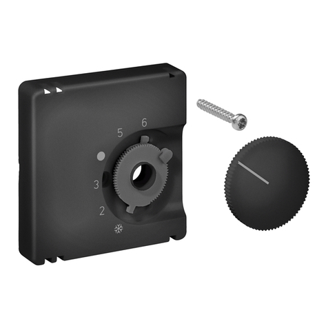
3.1. Bereichseinengung des Einstellbereichs
Mittels der Einstellfahnen unter dem Einstellknopf kann der Einstellbereich des Reglers mecha-
nisch begrenzt werden. Hierzu muss der Knopf abgezogen und nach verstellen der Anschläge (rot
für Maximaltemperatur, blau für Minimaltemperatur) wieder aufgesteckt werden.
3.1. Suppression of the setting range
The setting pins located underneath of the adjusting knob enable to delimit the setting range of
the controller mechanically. To enable this, the adjusting knob must be removed by pulling it off
and, after the adjustment of the related pins (end stops, red for max. temperature and blue for
min. temperature) be put on again.
3
2.3 Fonction économisante concernant la consommation d’énergie (mode de service ECO)
(ne s’applique pas au modèle 040.211)
L’opération en mode de service économisant (ECO) permet, durant le processus de chauffage, d’abais-
ser la température à une valeur plus inférieure et, durant le processus de refroidissement, à une valeur
plus élevée. L’écart de température entre la température réelle et la température de consigne préréglée
peut être ajusté à l’intérieur du dispositif dans un domaine de ±0,5 à ±2-5K. L’opération en mode de
service économisant (ECO) est déclenchée par un contact ECO externe ou, avec le modèle KTRRB-
040.213, aussi par l’interrupteur correspondant prévu à cet effet.
2.4 Voyants lumineux:
Lampe en haut:
Rouge = chauffage MARCHE
Vert = refroidissement MARCHE
OFF = température atteinte
Lampe en bas:
Rouge = interruption de l’opération durant mode de fonctionnement «refroidissement»
par raison de décongélation (formation de l’eau condensée à la conduite de refroidissement)
Vert = Indication du mode de service ECO (ne s’applique pas au modèle 040.211)
OFF = Opération en mode de service «confort»
2.4 Spie luminose
Spia, lato sinistro:
rossa = Riscaldamento inserito
verde = Raffreddamento inserito
spenta = Temperatura raggiunta
Spia, lato destro:
rossa = Interruzione raffreddamento per formazione
di rugiada (formazione di condensa su tubazione raffreddamento)
verde = Modalità ECO (non vale per il modello 040-211)
spenta = Modalità comfort
3. Installation
Le dispositif est prévu pour l’installation murale ou sur une boîte encastrée et ne doit pas être
exposé directement à des sources de chaleur ou de froid. Il faut également faire attention à ce que
le dispositif ne soit pas exposé à l’influence de sources de chaleur ou de froide, qui le chauffent
ou refroidissent à sa face arrière (par des courants d’air dans des murs creux ou par les tempéra-
tures répandues par des conduites montantes, par ex.). Lorsqu’il n’est pas possible d’exclure
complètement une telle influence thermique sur le régulateur, le point de zéro correspondant (voir
chapitre 9.) peut être ajusté intérieurement selon besoin. L’ajustage interne du point de zéro ne
doit cependant pas avoir lieu qu’après l’adaptation du régulateur à la température prédominante
(terminée après env. 45 minutes).
3. Installazione
Il termostato è concepito per il montaggio su parete o presa incassata, evitando esposizioni dirette
a sorgenti di calore o di freddo. Assicurarsi che il termostato non sia esposto nemmeno posterior-
mente al calore o al freddo, ad es. Su pareti cave per effetto di flussi d’aria o di tubi montanti. Se
non è possibile evitare completamente effetti termici costanti del termostato sul punto di mon-
taggio, allora si può adattare internamente il punto zero (vedi punto 9.) La regolazione del punto di
azzeramento interno può essere effettuata solo dopo che il termostato si è adattato alla tempera-
tura ambiente (circa 45 minuti).
Broche de réglage
pour la valeur
minimale
de température
Broche de réglage
pour la valeur
maximale
de température
Linguetta di
regolazione per
valore termico
massimo
Linguetta di
regolazione per
valore termico
minimo
4.Caractéristiques techniques
5. Accessoires
Tension d’alimentation et de commutation:
24V~/4Attention! Ne que basse tension de protec-
tion!
Puissance de coupure: 0,7A (courant de crête max. 0,8A <150 ms)
Etendue de réglage KTRRB-040.112: 5 … 30°C
Etendue de réglage KTRRB-040.213 /.211
Etendue de réglage complète 21°C ±8K
Ajustage du point de zéro (interne): 21°C (ajustage fait à l’usine) ±5K
Etendue de réglage durant service: point de zéro ±3K
Différentiel: env.1K
Echelle KTRRB-040.213 /.211: flèches gonflantes rouges et bleues avec point de zéro
Echelle KTRRB-040.112: échelle en °C
Puissance absorbée: 1,6W / 2,3VA
Détecteur: NTC, type interne
Raccordement électrique: bornes à vis (0,5 … 2,5 mm2)
Type de protection: IP30 (après installation correspondante)
Indice de protection: III
Installation: murale ou sur une boîte encastrée (Ø 55 mm)
Température ambiante: 0 … 40°C
Température de stockage: -20 … +70°C
Humidité de l’aire admissible: max. 95% r.h., non condensant
Matériel du boîtier et couleur: plastique (ABS), blanc pur (pareil à RAL 9010)
Equipement général: 2 lampes-témoins, resserrage de domaine mécanique
Equipement modèle KTRRB-040.112: Interrupteur «chauffage/refroidissement»
Equipement modèle KTRRB-040.213: Interrupteur «OFF/mode de service «confort» /
mode de service ECO»; lorsque l’interrupteur est en
position OFF, la fonction «protection antigel des
locaux »est active à des températures inférieures à 5°C
4.Dati tecnici
Tensione alimentazione e comando: 24V~/
4
Attenzione! Solo bassa tensione di sicurezza
Potenza di rottura: 0,7A (corrente di cresta max. 0,8A < 150 ms)
Campo regolazione KTRRB-040.112: 5 … 30°C
Campo regolazione
KTRRB-040.213 /.211
Complessivo: 21°C ±8K
Regolazione punto zero (internamente): 21°C (regolazione di fabbrica) ±5K
Campo regolazione in esercizio: Punto zero impostato ±3K
Differenziale: Circa 1K
Scala
KTRRB-040.213 /.211
:
Frecce ad effetto progressivo in rosso e blu con punto zero
Scala KTRRB-040.112: Scala °C
Assorbimento potenza: 1,6W / 2,3VA
Sensore: NTC, tipo interno
Connessione elettrica: Terminali a vite 0,5 … 2,5 mm
2
Tipo protezione: IP30 (dopo montaggio specifico)
Classe protezione: III
Montaggio: su parete o presa incassata (Ø 55 mm)
Temperatura ambiente: 0 … 40°C
Temperatura stoccaggio: -20 … +70°C
Umidità relativa ammessa: max. 96% r.H., non condensante
Materiale e colore scatola:
Materale sintetico ABS, bianco alpino (simile a RAL 9010)
Equipaggiamento generale:
2 spie di segnalazione, restringimento di campo meccanico
Equipaggiamento KTRRB-040.112: Interruttore «riscaldamento/raffreddamento»
Equipaggiamento KTRRB-040.213: Interruttore «OFF/modo comfort/modo ECO»; con posi-
zione interruttore «OFF» la funzione antigelo ambiente
è attiva a <5°C
– Détecteurs de point de condensation TPS 1, PTS 2 et TPS 3. Les détecteurs se distinguent par
leur construction qui permet de les utiliser pour des différents modes d’installation.
5. Accessori
– Sensori del punto di rugiada TPS-1, TPS-2 e TPS-3. I sensori del punto di rugiada differiscono
per l’esecuzione, idonea per diversi tipi di montaggio.
3.1. Limitation de la plage de réglage
Les broches de réglage existant en dessous du bouton de réglage permettent de limiter mécani-
quement la plage de réglage du régulateur. Afin de pouvoir faire ça, il faut d’abord enlever le
bouton de réglage et ensuite régler les limites (broche rouge pour la température maximale et
broche bleue pour la température minimale). Après ceci, le bouton de réglage peut être monté
encore.
3.1. Restringimento del campo di regolazione
Con le linguette di regolazione sotto la manopola si può limitare meccanicamente il campo di
regolazione del termostato. Allo scopo tirare la manopola e spingerla nuovamente in posizione
dopo aver regolato le battute (rosse per temperatura massima, blu per temperatura minima).
Die von uns genannten technischen Daten wurden unter Laborbedingungen nach allgemein gültigen Prüfvorschriften, insbesondere DIN-Vorschriften, ermittelt. Nur insoweit werden
Eigenschaften zugesichert. Die Prüfung der Eignung für den vom Auftraggeber vorgesehenen Verwendungszweck bzw. den Einsatz unter Gebrauchsbedingungen obliegt dem Auftrag-
geber; hierfür übernehmen wir keine Gewährleistung. Änderungen vorbehalten.
The technical data specified herein have been determined under laboratory conditions and in compliance with generally approved test regulations, in particular DIN standards. Technical
characteristics can only be warranted to this extent. The testing with regard to the qualification and suitability for the client’s intended application or the use under service conditions shall
be the client’s own duty. We refuse to grant any warranty with regard thereto. Subject to change without notice.
Les données techniques indiquées dans cette notice d’instructions ont été déterminées sous conditions laboratoires en conformité avec des prescriptions d’essai généralement approu-
vées, notamment les normes DIN. Les caractéristiques techniques ne peuvent être garanties que dans cette mesure. La vérification du dispositif en rapport à sa qualification et appropria-
tion pour l’application prévue ou son utilisation sous conditions de service incombe au client. Nous n’assumons aucune garantie à cet égard. Sous réserve de modifications techniques.
I dati tecnici indicati in queste avvertenze di montaggio sono stati rilevati in laboratorio in conformità con le norme di controllo correnti, soprattutto
con le norme DIN. La caratteristiche
tecniche vengono garantire solo in tale misura. Il controllo del dispositivo in relazione all’idoneità per lo scopo di destinazione previsto dal committente e all’impiego in condizioni di
servizio è a carico del cliente. Non assumiamo alcuna garanzia al riguardo. Salvo modifiche di ordine tecnico.
ALRE-IT Regeltechnik GmbH · Richard-Tauber-Damm 10 · D-12277 Berlin
Tel.: +49(0)30/399 84-0 · Fax: +49(0)30/391 70 05 · mail@alre.de · www.alre.de
4
6. Montagehinweise / Mounting information / Précision d’installation / Avvertenze di montaggio
7. Maßbild und Anschluss-Schaltbild / Dimensioned drawing and connection diagram /
Dessin coté et schéma de branchement / Schema quotato e schema di collegamento
8. Einstellungen / Settings / Ajustages / Regolazioni
KTRRB-040.211 KTRRB-040.112
––––––– Werkseinstellung
Factory setting
Ajustage fait à l’usine
Regolazione di fabbrica
––––– Einstellbereich
Setting range
Etendue de réglage
Campo di regolazione
ECO
Sollwert
Set value
Valeur de consigne
Valore nominale
Klemme 4
terminal 4
borne 4
terminale 4
On
Off
Klemme 4
terminal 4
borne 4
terminale 4
On
Off
Heizen
Heating
Chauffage
Riscaldare
Kühlen
Cooling
Refroidissement
Raffreddare
ECO-Zone
ECO zone
Zone ECO
Zona ECO
interner Sollwert / internal set point
valeur de consigne interne
valore nominale interno
Kontakt offen
Contact open
Contact ouvert
Contatto aperto
Temp. in Position „0“
Temp. in position “0”
Temp. en position «0»
Temp. in posizione «0»
Kühlen
Cooling
Refroidissement
Raffreddare
Klemme 4
terminal 4
borne 4
terminale 4
On
Off
Sollwert
Set value
Valeur de consigne
Valore nominale
Kontakt geschlossen
Contact closed
Contact fermé
Contatto chiuso
Klemme 4
terminal 4
borne 4
terminale 4
On
Off
Sollwert
Set value
Valeur de consigne
Valore nominale
Heizen
Heating
Chauffage
Riscaldare
T
T
T
T
9. Gewährleistung / Warranty / Garantie / Garanzia
21° C
16° C 26°C
KTRRB-040.213

This manual suits for next models

3

Other alre Thermostat manuals

alre FETR 101.745 User manual

alre

alre FETR 101.745 User manual

alre RTBSU-401.086 00 User manual

alre

alre RTBSU-401.086 00 User manual

alre RTBSU-401.2 Series User manual

alre

alre RTBSU-401.2 Series User manual

alre RTBSU-401.086 User manual

alre

alre RTBSU-401.086 User manual

alre JTF Series User manual

alre

alre JTF Series User manual

alre RFHSB-060.010 User manual

alre

alre RFHSB-060.010 User manual

alre KR Series User manual

alre

alre KR Series User manual

alre FETR 101.745 User manual

alre

alre FETR 101.745 User manual

alre RFHSU-010 User manual

alre

alre RFHSU-010 User manual

alre RKDSB-171.000 User manual

alre

alre RKDSB-171.000 User manual

Popular Thermostat manuals by other brands

System air TControl Easy DX-Air Curtain Data Sheet / Manual

System air

System air TControl Easy DX-Air Curtain Data Sheet / Manual

C.P. Electronics ENERSTAT-T Product guide

C.P. Electronics

C.P. Electronics ENERSTAT-T Product guide

Environmental Technologies SST–2 40 Installation and operation manual

Environmental Technologies

Environmental Technologies SST–2 40 Installation and operation manual

MO-EL 9006 user manual

MO-EL

MO-EL 9006 user manual

Pro 1 IAQ T631W-2 operating manual

Pro 1 IAQ

Pro 1 IAQ T631W-2 operating manual

MCOHome MH6-HP user manual

MCOHome

MCOHome MH6-HP user manual

Moe's 002 Series user manual

Moe's

Moe's 002 Series user manual

MCOHome MH7-WH user manual

MCOHome

MCOHome MH7-WH user manual

Alarmcom ADC-T2000 product manual

Alarmcom

Alarmcom ADC-T2000 product manual

ComfortHeat C 101 manual

ComfortHeat

ComfortHeat C 101 manual

Cellar Cool WM 2500 owner's manual

Cellar Cool

Cellar Cool WM 2500 owner's manual

eControls Comfort365 C365W21 user manual

eControls

eControls Comfort365 C365W21 user manual

V-tech W960 quick start guide

V-tech

V-tech W960 quick start guide

Pro 1 IAQ T721i Operation manual

Pro 1 IAQ

Pro 1 IAQ T721i Operation manual

ensto ECO16TOUCH user manual

ensto

ensto ECO16TOUCH user manual

Carrier HYPERSTAT installation guide

Carrier

Carrier HYPERSTAT installation guide

iSNATCH 49.6935.33 manual

iSNATCH

iSNATCH 49.6935.33 manual

ritetemp 8025 Operation guide

ritetemp

ritetemp 8025 Operation guide

manuals.online logo
manuals.online logoBrands
  • About & Mission
  • Contact us
  • Privacy Policy
  • Terms and Conditions

Copyright 2025 Manuals.Online. All Rights Reserved.