alre RTBSU-401.086 User manual

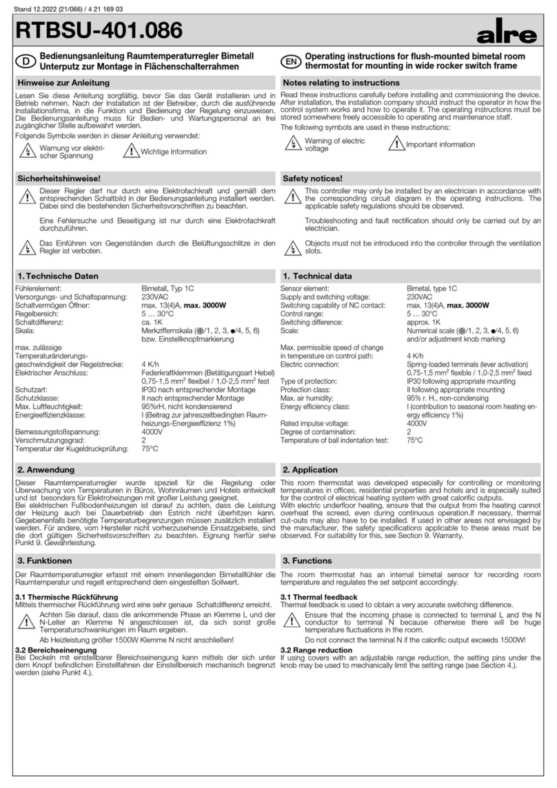
RTBSU-401.086
Bedienungsanleitung Raumtemperaturregler Bimetall
Unterputz zur Montage in Flächenschalterrahmen
Sicherheitshinweise!
2. Anwendung
Dieser Raumtemperaturregler wurde speziell für die Regelung oder
Überwachung von Temperaturen in Büros, Wohnräumen und Hotels entwickelt
und ist besonders für Elektroheizungen mit großer Leistung geeignet.
Bei elektrischen Fußbodenheizungen ist darauf zu achten, dass die Leistung
der Heizung auch bei Dauerbetrieb den Estrich nicht überhitzen kann.
Gegebenenfalls benötigte Temperaturbegrenzungen müssen zusätzlich installiert
werden. Für andere, vom Hersteller nicht vorherzusehende Einsatzgebiete, sind
die dort gültigen Sicherheitsvorschriften zu beachten. Eignung hierfür siehe
Punkt 9. Gewährleistung.
3. Funktionen
Der Raumtemperaturregler erfasst mit einem innenliegenden Bimetallfühler die
Raumtemperatur und regelt entsprechend dem eingestellten Sollwert.
3.1 Thermische Rückführung
Mittels thermischer Rückführung wird eine sehr genaue Schaltdifferenz erreicht.
Achten Sie darauf, dass die ankommende Phase an Klemme L und der
N-Leiter an Klemme N angeschlossen ist, da sich sonst große
Temperaturschwankungen im Raum ergeben.
Ab Heizleistung größer 1500W Klemme N nicht anschließen!
3.2 Bereichseinengung
Bei Deckeln mit einstellbarer Bereichseinengung kann mittels der sich unter
dem Knopf befindlichen Einstellfahnen der Einstellbereich mechanisch begrenzt
werden (siehe Punkt 4.).
Hinweise zur Anleitung
Lesen Sie diese Anleitung sorgfältig, bevor Sie das Gerät installieren und in
Betrieb nehmen. Nach der Installation ist der Betreiber, durch die ausführende
Installationsfirma, in die Funktion und Bedienung der Regelung einzuweisen.
Die Bedienungsanleitung muss für Bedien- und Wartungspersonal an frei
zugänglicher Stelle aufbewahrt werden.
Folgende Symbole werden in dieser Anleitung verwendet:
Warnung vor elektri-
scher Spannung Wichtige Information
1. Technische Daten
Fühlerelement: Bimetall, Typ 1C
Versorgungs- und Schaltspannung: 230VAC
Schaltvermögen Öffner: max. 13(4)A, max. 3000W
Regelbereich: 5 … 30°C
Schaltdifferenz: ca. 1K
Skala: Merkziffernskala ( 2 3 5 6)
bzw. Einstellknopfmarkierung
max. zulässige
Temperaturänderungs-
geschwindigkeit der Regelstrecke: 4 K/h
Elektrischer Anschluss: Federkraftklemmen (Betätigungsart Hebel)
0,75-1,5 mm² flexibel / 1,0-2,5 mm² fest
Schutzart: IP30 nach entsprechender Montage
Schutzklasse: II nach entsprechender Montage
Max. Luftfeuchtigkeit: 95%rH, nicht kondensierend
Energieeffizienzklasse: I (Beitrag zur jahreszeitbedingten Raum-
heizungs-Energieeffizienz 1%)
Bemessungstoßspannung: 4000V
Verschmutzungsgrad: 2
Temperatur der Kugeldruckprüfung: 75°C
Dieser Regler darf nur durch eine Elektrofachkraft und gemäß dem
entsprechenden Schaltbild in der Bedienungsanleitung installiert werden.
Dabei sind die bestehenden Sicherheitsvorschriften zu beachten.
Eine Fehlersuche und Beseitigung ist nur durch eine Elektrofachkraft
durchzuführen.
Das Einführen von Gegenständen durch die Belüftungsschlitze in den
Regler ist verboten.
Operating instructions for flush-mounted bimetal room
thermostat for mounting in wide rocker switch frame
Safety notices!
2. Application
This room thermostat was developed especially for controlling or monitoring
temperatures in offices, residential properties and hotels and is especially suited
for the control of electrical heating system with great calorific outputs.
With electric underfloor heating, ensure that the output from the heating cannot
overheat the screed, even during continuous operation.If necessary, thermal
cut-outs may also have to be installed. If used in other areas not envisaged by
the manufacturer, the safety specifications applicable to these areas must be
observed. For suitability for this, see Section 9. Warranty.
3. Functions
The room thermostat has an internal bimetal sensor for recording room
temperature and regulates the set setpoint accordingly.
3.1 Thermal feedback
Thermal feedback is used to obtain a very accurate switching difference.
Ensure that the incoming phase is connected to terminal L and the N
conductor to terminal N because otherwise there will be huge
temperature fluctuations in the room.
Do not connect the terminal N if the calorific output exceeds 1500W!
3.2 Range reduction
If using covers with an adjustable range reduction, the setting pins under the
knob may be used to mechanically limit the setting range (see Section 4.).
Notes relating to instructions
Read these instructions carefully before installing and commissioning the device.
After installation, the installation company should instruct the operator in how the
control system works and how to operate it. The operating instructions must be
stored somewhere freely accessible to operating and maintenance staff.
The following symbols are used in these instructions:
Warning of electric
voltage Important information
1. Technical data
Sensor element: Bimetal, type 1C
Supply and switching voltage: 230VAC
Switching capability of NC contact: max. 13(4)A,
max. 3000W
Control range: 5 … 30°C
Switching difference: approx. 1K
Scale: Numerical scale ( 2 3 5 6)
and/or adjustment knob marking
Max. permissible speed of change
in temperature on control path: 4 K/h
Electric connection: Spring-loaded terminals (lever activation)
0,75-1,5 mm² flexible / 1,0-2,5 mm² fixed
Type of protection: IP30 following appropriate mounting
Protection class: II following appropriate mounting
Max. air humidity: 95% r. H., non-condensing
Energy efficiency class: I (contribution to seasonal room heating en-
ergy efficiency 1%)
Rated impulse voltage: 4000V
Degree of contamination: 2
Temperature of ball indentation test: 75°C
This controller may only be installed by an electrician in accordance with
the corresponding circuit diagram in the operating instructions. The
applicable safety regulations should be observed.
Troubleshooting and fault rectification should only be carried out by an
electrician.
Objects must not be introduced into the controller through the ventilation
slots.
DEN
Stand 11.2019 / 4 21 169 01

6. Bediensymbole
Die angegebenen technischen Daten wurden durch uns jeweils in einem dafür
geeigneten Prüf- und Testumfeld (hierzu geben wir auf Anfrage Auskunft) ermittelt und
stellen nur auf dieser Grundlage die vereinbarte Beschaffenheit dar. Die Prüfung der
Eignung für den vom Auftraggeber / Kunden vorgesehenen Verwendungszweck oder
den Einsatz unter den konkreten Gebrauchsbedingungen obliegt dem Auftraggeber /
Kunden; hierfür übernehmen wir keine Gewährleistung. Änderungen vorbehalten
.
9. Gewährleistung
7. Reinigung
8. Demontage / Entsorgung
Die Montage und der elektrische Anschluss dürfen nur im
spannungsfreien Zustand erfolgen.
Der Anschluss der elektrischen Leiter erfolgt entsprechend des Schaltbildes
(siehe Punkt 5.). Die Abisolierlänge von 7 mm ist zu beachten. Bei Verwendung
von flexiblen Drähten sind Aderendhülsen zu verwenden.
Je nach Lieferumfang wird der Regler ohne oder mit Deckel, Einstellknopf
und ggf. Schalterrahmen geliefert. Der Regler ist zur Montage in die UP-Dose
bestimmt und darf nicht direkt Wärme- oder Kältequellen ausgesetzt werden. Es
ist darauf zu achten, dass der Regler auch rückseitig keiner Fremderwärmung
oder -kühlung, z.B. bei Hohlwänden durch Zugluft oder Steigleitungen,
ausgesetzt wird (siehe Abb. 2).
Der Regler mit dem 50 x 50 mm Deckel ist mittels Zwischenrahmen der
Schalterhersteller nach DIN 49075 in nahezu alle Schalterprogramme
integrierbar. Der Regler mit dem 55 x 55 mm Deckel ist ebenfalls für diverse
Schalterprogramme geeignet. Bei Mehrfachrahmen ist der Regler immer an
unterster Stelle zu montieren.
Für die Befestigungsschraube des Deckels Serie Berlin-Unterputz ist je nach
verwendeter Schraube ein PZ 1 bzw. T7 Schraubendreher zu verwenden.
Um den Einstellbereich bei Deckeln mit einstellbarer Bereichseinengung
einzuengen, wird der sich unter dem Einstellknopf befindliche Stift abgezogen
und die Einstellfahnen verstellt (rot für maximal und blau für minimal mögliche
Einstellung). Anschließend wird der Stift wieder eingesteckt und somit die
Begrenzungen arretiert (siehe Abb. 3).
4. Montage / Elektrischer Anschluss
Die Reinigung des geöffneten Gerätes ist verboten. Staub und Schmutz
vom Deckel, Einstellknopf und Rahmen vorsichtig mit einem trockenen,
lösungsmittelfreien und weichen Tuch entfernen.
Vor der Demontage Regler und alle angeschlossenen Geräte
spannungsfrei schalten und gegen Wiedereinschalten sichern.
Gerät demontieren und fachgerecht entsorgen.
5.
Anschluss-Schaltbild u. Klemmensymbole
Regler 50 x 50
mit alre-Standard-
Rahmen
50 x 50 controller
with alre standard
frame
Regler 50 x 50 mit
Beispiel-Rahmen und
Zwischenrahmen
50 x 50 controller with
sample frame and in-
termediate frame
Regler 55 x 55 mit
Beispiel-Rahmen
55 x 55 controller with
sample frame
Abb. 1
Fig. 1
Abb. 2
Fig. 2
Temperatur-Wohlfühlpunkt (entspricht ca. 20°C)
Frostschutz (entspricht ca. 5°C)
LPhase Versorgungsspannung
NNeutralleiter
Ausgang Heizen
Abb. 3
Fig. 3
Einstellfahne für
minimalen
Temperaturwert
Setting pin for mi-
nimum
temperature value
Einstellfahne für ma-
ximalen
Temperaturwert
Setting pin for ma-
ximum
temperature value
A
A
(2 : 1)
6.
Control symbols
We determined the technical data provided in an inspection and test environment
suited to this task (we are happy to provide details on request) and this data only
presents the agreed properties on this basis. The purchaser / customer is responsible
for checking the suitability of the use or usage intended by the purchaser / customer
under the specific conditions of use; we do not accept any liability for this. We reserve
the right to amendments
.
9. Warranty
7. Cleaning
8. Removal / disposal
Mounting and the electric connection may only be undertaken when de-
energised.
The electric conductors are connected according to the circuit diagram (see
Section 5.). The insulation stripping length of 7 mm should be observed. If using
flexible wires, ferrules should be used.
Depending on the scope of supply, the controller is supplied with or without a
cover, adjustment knob and if necessary switch frame. The controller is intended
for mounting in the flush-mounted socket and must not be exposed to direct
sources of heat or cold. Ensure that the controller is not exposed to external
heating or cooling at the rear, e.g. with wooden walls from draughts or rising
mains (see Fig. 2).
The controller with the 50 x 50 mm cover can be integrated into virtually
all switch ranges using intermediate frames from switch manufacturers in
accordance with DIN 49075. The controller with the 55 x 55 mm cover is also
suitable for various switch ranges. With multiple frames, the controller should
always be fitted in the bottom position.
Depending on the screw used, a PZ 1 or T7 screwdriver should be used for the
mounting screw of the cover for the Berlin flush-mounted series.
In order to reduce the setting range for covers with adjustable range reduction,
the pin under the adjustment knob is pulled out and the setting pins adjusted
(red for maximum and blue for minimum setting available). The pin is then re-
inserted and the limits thereby locked (see Fig. 3).
4. Mounting / electric connection
The opened device must not be cleaned. Carefully remove dust and dirt
from the cover, adjustment knob and frame using a dry, solvent-free and
soft cloth.
Before removal, de-energise the controller and all connected devices and
lock so they cannot be switched on again.
Remove device and dispose of correctly.
5. Connection diagrams and
terminal symbols
Comfortable temperature point (equivalent to approx. 20°C)
Frost protection (equivalent to approx. 5°C)
LSupply voltage phase
NNeutral conductor
Heating output
Achtung:
Ab Heizleistung größer 1500W
Klemme N nicht anschließen!
Caution:
Do not connect the terminal N
if the calorific output exceeds
1500W!

Notice d’utilisation régulateur de température ambiante bimétal
encastrable pour montage dans cadre d’interrupteur de surface
Consignes de sécurité!
2. Application
Ce régulateur de température ambiante a été spécialement développé pour
réguler ou surveiller les températures dans des bureaux, des pièces d’habitation
et des hôtels et convient particulièrement aux appareils de chauffage électriques
de forte puissance.
Avec des chauffages au sol électriques, il convient de veiller à ce que la
puissance du chauffage n'occasionne pas une surchauffe de la chape même en
mode de fonctionnement continu.
Des limitations de température nécessaires doivent être installées en supplément
le cas échéant. Pour les autres domaines d’application non prévus par le
fabricant, les directives de sécurité applicables sur site doivent être respectées.
Pour la conformité, voir au point9. Garantie.
3. Fonctions
Le régulateur de température ambiante détecte à l’aide d’une sonde interne
bimétal la température ambiante et régule en conséquence la valeur de consigne
réglée.
3.1 Retour thermique
Le retour thermique permet une différence de commutation très précise.
Veillez à ce que la phase entrante soit raccordée à la borne L et le
conducteur N à la borne N, faute de quoi la pièce pourrait être soumise à
de fortes variations de température. Ne raccordez pas la borne N pour
une capacité de chauffage supérieure à 1500 W!
3.2 Rétrécissement de plage
Sur les couvercles présentant un rétrécissement de plage, il est possible de
limiter mécaniquement la plage de réglage à l’aide du talon de réglage situé sous
le bouton (voir Point4.).
Remarques concernant cette notice
Veuillez lire attentivement cette notice avant d'installer et de mettre en service
l’appareil. Après l’installation, l’exploitant doit être formé au fonctionnement et
à l’utilisation de la régulation par la société installatrice. La notice d’utilisation
doit être conservée dans un endroit accessible au personnel de commande et
d’entretien.
Les symboles suivants sont utilisés dans cette notice:
Information importante
1. Caractéristiques techniques
Élément de sonde: bimétal, type1C
Tension d’alimentation et
de commutation: 230 VAC
Capacité de commutation
contact d’ouverture: 13(4)A max., max. 3000W
Plage de régulation: 5 … 30°C
Différence de commutation: env. 1K
Échelle:
échelle de chiffres repères ( 2 3 5 6)
ou marquage du bouton de réglage
Vitesse de changement de
température max.
autorisée du parcours de régulation: 4K/h
Raccordement électrique: bornes à ressort (type d’actionnement
à levier)
0,75-1,5 mm² flexible / 1,0-2,5 mm² fixe
Degré de protection: IP30 après montage correspondant
Classe de protection: II après montage correspondant
Humidité de l’air max.: 95% rH, non condensant
Classe d’efficacité énergétique: I (contribution à l’efficacité énergétique
du chauffage ambiant saisonnier 1%)
Surtension transitoire de mesure: 4000V
Degré d’encrassement: 2
Température de l’essai de billage: 75°C
Ce régulateur doit être installé uniquement par un électricien qualifié et
conformément au schéma de raccordement correspondant figurant dans
la notice d’utilisation. Les consignes de sécurité en vigueur doivent être
respectées.
La recherche d’erreur et les réparations doivent être entreprises
uniquement par un électricien qualifié.
Il est interdit d’introduire des objets dans le régulateur par les fentes
d’aération.
Istruzioni per l’uso del termostato per la regolazione della temperatura ambien-
te bimetallico sottotraccia per montaggio in telaio per interruttore a pulsante
Avvertenze di sicurezza!
2. Utilizzo
Questo termostato per la regolazione della temperatura ambiente è stato
appositamente sviluppato per regolare o monitorare la temperatura di uffici,
spazi abitativi e hotel ed è particolarmente adatto per riscaldatori elettrici ad alta
potenza.
In presenza di riscaldamento elettrico a pavimento, occorre verificare che la
potenza del riscaldamento non possa surriscaldare il massetto anche in caso di
funzionamento continuo.
Limitatori di temperatura eventualmente necessari devono essere installati
a parte. Per altri campi di impiego non prevedibili da parte del produttore,
rispettare le prescrizioni di sicurezza applicabili. Per la relativa idoneità vedere il
punto 9. Garanzia
3. Funzioni
Il termostato per la regolazione della temperatura ambiente rileva la temperatura
ambiente con un sensore bimetallico interno e regola di conseguenza il valore
nominale impostato.
3.1 Retroazione termica
La retroazione termica consente di raggiungere un intervallo differenziale molto
preciso.
Verificare che la fase in entrata sia collegata al morsetto L e il conduttore
N al morsetto N, poiché altrimenti nell'ambiente si verificheranno grandi
oscillazioni di temperatura. Dalla capacità di riscaldamento superiore a
1500 W, non collegare il terminale N!
3.2 Limitazione del range
Nei coperchi con limitazione del range regolabile, le apposite linguette al di sotto
della manopola consentono di limitare meccanicamente il range di regolazione
(vedere punto 4.).
Avvertenze sulle presenti istruzioni
Leggere attentamente le presenti istruzioni prima di installare o mettere in
funzione il dispositivo. La ditta che ha eseguito l’installazione deve illustrare
all’utente come utilizzare il dispositivo di regolazione e le sue funzioni. Le
istruzioni per l’uso devono essere conservate in un luogo accessibile per poter
essere consultate da utenti e personale di manutenzione.
Nelle presenti istruzioni vengono utilizzati i seguenti simboli:
Avvertenza di tensione
elettrica
1. Dati tecnici
Elemento sensore: Bimetallico, tipo 1C
Tensione di alimentazione
e commutazione: 230 V CA
Potere di interruzione contatto
di apertura: max. 13(4) A, max. 3000W
Range di regolazione: 5 … 30°C
Intervallo differenziale: ca. 1 K
Scala: Scala a più cifre ( 2 3 5 6)
o marcatura manopola di regolazione
Velocità di variazione della
temperatura massima ammessa
del percorso di regolazione: 4 K/h
Collegamento elettrico: Morsetti a innesto (tipo di aziona-
mento leva)
0,75-1,5 mm² flessibili / 1,0-2,5 mm² fissi
Tipo di protezione: IP30 con montaggio corretto
Classe di protezione: II con montaggio corretto
Umidità dell’aria max: 95% rH, senza condensazione
Classe di efficienza energetica: I (contributo all’efficienza energe-
tica stagionale del riscaldamento
d’ambiente 1%)
Tensione impulsiva di
dimensionamento: 4000 V
Grado di contaminazione: 2
Temperatura prova di durezza Brinell: 75°C
Il presente dispositivo di regolazione può essere installato solo da un
elettricista qualificato e conformemente al relativo schema elettrico
riportato nelle istruzioni per l’uso. A tale scopo devono essere rispettate
le norme di sicurezza vigenti.
Ricerca ed eliminazione guasti possono essere effettuate solo da un
elettricista qualificato.
È vietato introdurre oggetti nella fessura di ventilazione del dispositivo di
regolzione.
Informazione importante
Avertissement de tension
électrique
F IT
6. Symboles de commande
Les caractéristiques techniques indiquées ont été définies par nos soins
respectivement dans un environnement de contrôle et de test approprié
(possibilité de vous faire parvenir des informations sur demande) et constituent
uniquement sur cette base la qualité convenue. Le contrôle de conformité à
l’usage prévu par le donneur d’ordre / le client ou à l’usage dans des conditions
d’utilisation concrètes incombe au donneur d‘ordre/ au client; nous déclinons à
ce sujet toute garantie. Sous réserves de modifications.
9. Garantie
ALRE-IT Regeltechnik GmbH · Richard-Tauber-Damm 10 · D-12277 Berlin
7. Nettoyage
8. Démontage / Mise au rebut
Le montage et le raccordement électrique doivent être entrepris
uniquement à l’état hors tension.
Le raccordement des conducteurs électriques s‘effectue conformément au
schéma de raccordement (voir Point5.). La longueur dénudée de 7mm doit être
respectée. Des embouts doivent être utilisés sur les fils métalliques flexibles.
Suivant l’étendue de la fourniture, le régulateur est livré avec ou sans couvercle,
bouton de réglage et le cas échéant cadre d‘interrupteur. Le régulateur est
destiné à être installé dans un boîtier encastré et ne doit pas être exposé à des
sources de chaleur ou de froid directes. Il convient de veiller à ce que l’arrière du
régulateur ne soit pas exposé non plus à une source externe de chaleur ou de
froid, p. ex. courant d’air ou conduites montantes en cas de parois creuses (voir
Fig.2). Le régulateur muni d‘un couvercle 50 x 50 mm peut être intégré dans
quasiment tous les programmes d‘interrupteur à l’aide du cadre intermédiaire
des fabricants d’interrupteur conformément à DIN 49075. Le régulateur muni
d‘un couvercle 55 x 55 mm est également approprié pour divers programmes
d‘interrupteur. En cas d’installation dans des cadres multiples, le régulateur doit
toujours être monté à l’endroit le plus bas. Pour la vis de fixation du couvercle de
la série Berlin-Encastrable, utiliser un tournevis PZ1 ou T7 selon le type de vis.
Pour réduire la plage de réglage sur les couvercles avec un rétrécissement de
plage réglable, tirer sur la tige située sous le bouton de réglage et déplacer
les talons de réglage (rouge pour le réglage maximal possible et bleu pour le
réglage minimal possible). Enfoncer à nouveau la tige pour bloquer les limitations
(voirFig.3).
4. Montage / Raccordement électrique
Il est interdit de nettoyer l’appareil ouvert. Retirer avec précaution avec
un chiffon doux, sec et sans solvant la poussière, les salissures sur le
couvercle, le bouton de réglage et le cadre.
Avant le démontage, mettre hors tension le régulateur et tous les
appareils raccordés et les protéger d‘une remise sous tension.
Démonter l’appareil et le mettre au rebut de manière conforme.
5.
Schéma de raccordement et symboles des bornes
Régulateur 50 x 50
avec cadre standard
alre
Dispositivo di regolazio-
ne 50 x 50 con vecchio
telaio standard
Régulateur 50 x 50 avec
exemple de cadre et cadre
intermédiaire
Dispositivo di regolazione 50
x 50 con telaio esemplifica-
tivo e telaio intermedio
Régulateur 55 x 55 avec
exemple de cadre
Dispositivo di regolazi-
one 55 x 55 con telaio
esemplificativo
Fig.1
Fig.2
Température point de bien-être (correspond à 20°C)
Protection contre le gel (correspond à 5°C)
LPhase tension d’alimentation
NConducteur neutre
Sortie chauffage
Fig.3
Talon de réglage
pour valeur de tem-
pérature minimale
Linguetta di rego-
lazione del valore
di temperatura
minimo
Talon de réglage
pour valeur de tem-
pérature maximale
Linguetta di regolazi-
one del valore di
temperatura massimo
A
A
(2 : 1)
6. Simboli operativi
I dati tecnici indicati sono stati da noi rilevati in un ambiente di prova e di test
adeguato a tale scopo (maggiori informazioni su richiesta) e presentano le
caratteristiche stabilite solamente sulla base delle suddette condizioni. La verifica
di idoneità per lo scopo di destinazione previsto dal committente / cliente oppure
per l’impiego in concrete condizioni di servizio è a carico del committente
/ cliente. La nostra azienda non si assume alcuna garanzia al riguardo. Salvo
modifiche.
9. Garanzia
7. Pulizia
8. Smontaggio / Smaltimento
Montaggio e collegamento elettrico possono essere effettuati soltanto in
assenza di tensione.
Il collegamento dei conduttori elettrici avviene secondo lo schema elettrico
(vedere punto 5). Considerare una lunghezza di isolamento di 7 mm. In caso di
utilizzo di fili flessibili usare capicorda.
A seconda della dotazione, il dispositivo di regolazione viene fornito con o senza
coperchio, manopola di regolazione ed eventualmente telaio per interruttore.
Il dispositivo di regolazione deve essere installato nella presa a incasso e non
deve essere esposto a fonti dirette di calore o di freddo. È importante verificare
che il dispositivo di regolazione non sia esposto neanche posteriormente a fonti
di calore o di raffreddamento esterne, ad es.correnti d’aria oppure condutture
verticali in caso di pareti cave (vedere fig. 2). Il dispositivo di regolazione con
coperchio 50 x 50 mm può essere integrato mediante telaio intermedio del
produttore dell’interruttore a norma DIN 49075 in quasi tutti i supporti per
interruttori. Anche il dispositivo di regolazione con coperchio 55 x 55 mm è
adatto a diversi supporti per interruttori. In caso di telaio multiplo il dispositivo di
regolazione deve essere montato al livello inferiore. A seconda della vite utilizzata
per il fissaggio del coperchio Serie Berlin-sottotraccia, impiegare un cacciavite
PZ 1 o T7.
Per limitare il range di regolazione nel caso di coperchi con limitazione del range
regolabile, estrarre la spina al di sotto della manopola e spostare l’apposita
linguetta (rosso per regolazione massima e blu per regolazione minima possibile).
Quindi reinserire la spina per bloccare così le limitazioni (vedere fig. 3).
4. Montaggio / Collegamento elettrico
È vietato pulire il dispositivo aperto. Rimuovere con cautela polvere e
sporco da coperchio, manopola di regolazione e telaio con un panno
asciutto, morbido e privo di solventi.
Prima dello smontaggio, togliere tensione dal dispositivo di regolazione e
da tutti i dispositivi collegati e assicurarli contro il suo ripristino.
Smontare il dispositivo e smaltirlo a regola d’arte.
5.
Schema degli allacciamenti elettrici e simboli dei morsetti
Temperatura punto di benessere (corrisponde a ca. 20°C)
Protezione antigelo (corrisponde a ca. 5°C)
LFase tensione di alimentazione
NConduttore neutro
Uscita riscaldamento
Attention:
Ne raccordez pas la borne N pour
une capacité de chauffage supéri-
eure à 1500 W!
Attenzione:
Dalla capacità di riscaldamento
superiore a 1500 W, non collegare
il terminale N!
Other alre Thermostat manuals

alre
alre KR Series User manual

alre
alre RFHSU-010 User manual

alre
alre RTBSU-401.086 00 User manual

alre
alre KTRRB-040.112 User manual

alre
alre RFHSB-060.010 User manual

alre
alre RTBSU-401.2 Series User manual

alre
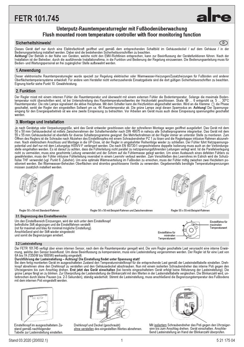
alre FETR 101.745 User manual

alre
alre FETR 101.745 User manual

alre
alre RKDSB-171.000 User manual

alre
alre JTF Series User manual