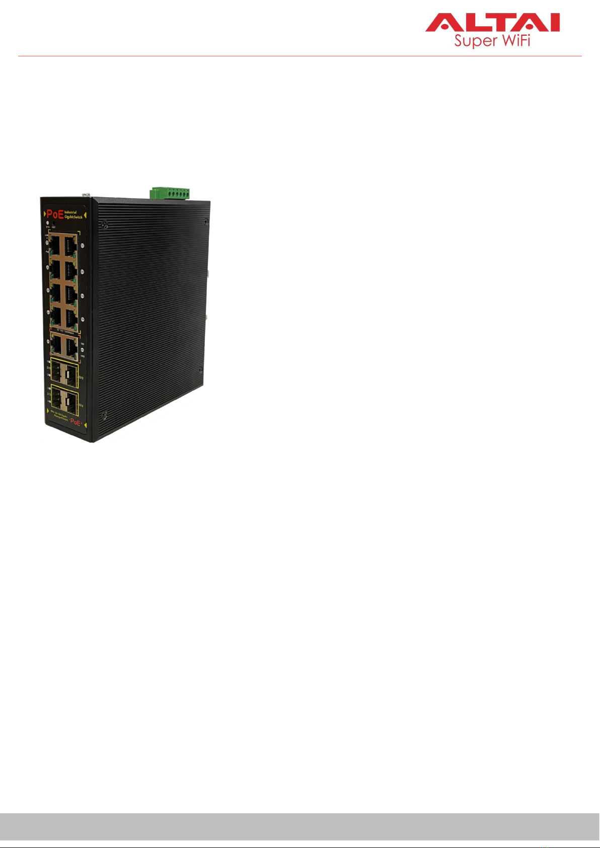
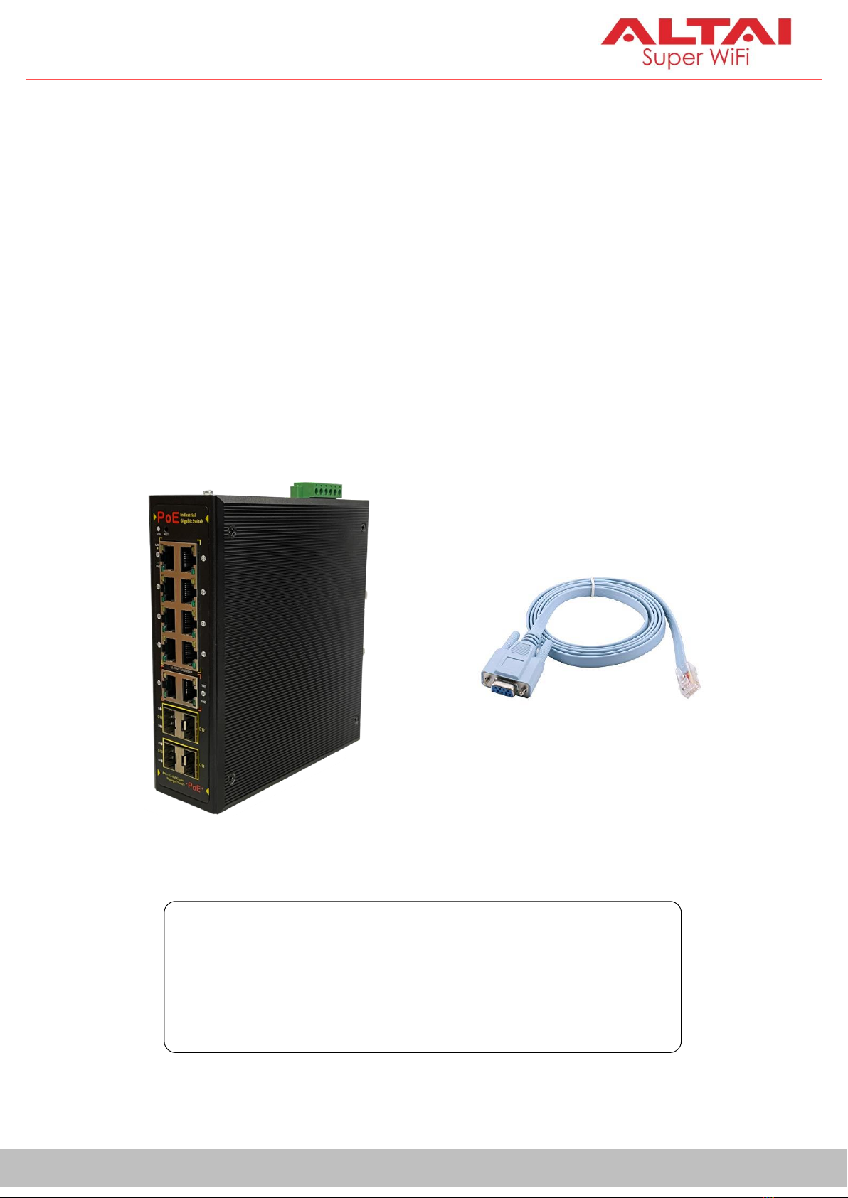
ALTAI MIS200P User manual

1
Altai Technologies Ltd. All rights reserved
Quick Setup Guide
ALTAI MIS200P
Industrial 14-Gigabit-Port
Managed PoE Switch
______________________________________________
Quick Setup Guide
Version 1.1

2
Altai Technologies Ltd. All rights reserved
Quick Setup Guide
1. Introduction
Thank you for purchasing the Altai MIS200P product. This guide provides
instructions to install the product and set it up with minimal effort.
2. Package Content
•MIS200P Main Unit x 1 pc
•DC Terminal Block Connector x 1 pc
•35mm DIN-rail Mounting Kit x 1 pc
•RJ-45 to RS232 DB9 Console Cable x 1 pc

3
Altai Technologies Ltd. All rights reserved
Quick Setup Guide
3. Product Description
Altai MIS200P is an industrial-grade managed switch featuring eight 1GbE
PoE ports, two 1GbE copper ports and four 100/1000BASE-X SFP slots. The
switch, with a rugged IP40 metal case and an ultra-wide temperature range
from -40°C to 80°C, is designed to operate in harsh industrial environments
such as factory, warehouse, and container port.
The switch supports 802.3af/at Power over Ethernet, a system to transmit
electrical power up to 30 watts, along with data, to remote devices over
standard twisted-pair Ethernet cable. Each MIS200P has eight 1GbE P.S.E.
ports, with a total power budget of 240W.
The MIS200P supports the advanced ITU-T G.8032 ERPS (Ethernet Ring
Protection Switching) redundant ring technology and Spanning Tree
Protocols (STP/RSTP/MSTP) for enhancing the system reliability and uptime of
any industrial networks. In a ring topology, the recovery time of the data link
can be as low as 20 ms.

4
Altai Technologies Ltd. All rights reserved
Quick Setup Guide
4. Feature Highlights
•Eight 10/100/1000BASE-T PoE RJ-45 ports with auto MDI/MDI-X function
•Two 10/100/1000BASE-T Copper RJ-45 ports with auto MDI/MDI-X function
•Four 100/1000BASE-X SFP slots
•IP 40 aluminum case
•DC redundant power input with polarity reverse protection
•DIN rail mount
•4 kV power and data port surge protection
•8 kV Ethernet ESD protection
•Support ERPS redundant ring technology with recovery time down to 20ms
•Support STP/RSTP/MSTP
•Support up to 255 VLAN groups and 4094 VLAN IDs
•Support IGMP snooping v1/v2
•Support 802.1X RADIUS user access authentication
•Support SSH, SSL, and SNMP v1/v2/v3 management
•Support status monitoring by AltaiGate or AltaiCare On Premises

5
Altai Technologies Ltd. All rights reserved
Quick Setup Guide
5. Applications
Deployment Scenario 1
The MIS200P is specifically designed to work with Altai APs. A typical use case
is as an access switch for an outdoor site, where multiple APs and other
devices are co-located.
Power + Data over Ethernet
Cable to 802.3af/at PD
Data over Ethernet Cable
Fiber Optic Cable
48-57V DC
Access
Point
IP Camera
Industrial PC
LAN
ERPS Ring
MIS200P
AltaiCare/AltaiGate
IoT Gateway

6
Altai Technologies Ltd. All rights reserved
Quick Setup Guide
Deployment Scenario 2
With its anti-shock and anti-vibration capabilities, the switch can readily be
used in an RTG or AGV for connecting a Wi-Fi CPE such as A2x and VX200 to
VMT (Vehicle-Mounted Terminal) and Camera.
18-32V DC
Quay Crane
AGV
RTG
Mobility Applications in Container Terminal:
Vehicle-Mounted
Terminal
IP Camera
CPE
MIS200P
Access Point

7
Altai Technologies Ltd. All rights reserved
Quick Setup Guide
6. Hardware Overview
Physical Dimensions
Front Panel
Back Panel
165 mm
A
C
E
F
G
B
I
D
H
J

8
Altai Technologies Ltd. All rights reserved
Quick Setup Guide
Top Panel
A: PoE Ports (G1-G8)
8 x 10/100/1000BASE-T RJ-45 ports for data and power transmission. Each port
can provide up to max. 30W of power for 802.3af/at-compatible PDs
(Powered Devices) such as IP cameras and access points. It is
recommended to use Cat. 5/5e/6 UTP (unshielded twisted pair) or STP
(shielded twisted pair) of Ethernet cables for the connection. Cable run can
be up to 100 meters. Below is the table about the cable specifications.
Cable Categories
Supported Ethernet Signal
Max. Length
Connector
Cat. 5 UTP/STP
10/100BASE-T
100 m (328 ft)
RJ-45
Cat. 5e UTP/STP
10/100/1000BASE-T
100 m (328 ft)
RJ-45
Cat. 6 UTP/STP
10/100/1000BASE-T
100 m (328 ft)
RJ-45
Two wiring standards can be used for a RJ-45 connector: T568A or T568B. The
latter one is preferable for new networks. For details of pin assignments of
T568A/T568B wiring specifications, see Appendix A and B.
K
M
L

9
Altai Technologies Ltd. All rights reserved
Quick Setup Guide
MIS200P switch also supports auto MDI/MDI-X operation. Therefore, you can
use either straight-through or crossover cables to connect the switch with
any other network devices. For simplicity, it is recommended to use straight-
through cables. For details of wiring for a straight-through or crossover cable
using T568B specification, see Appendix C and D.
Each port comes with two LEDs: Link and PoE to show its working status. For
details, see Section F and Grespectively.
B: Copper Ports (G9-G10)
2 extra ports of 10/100/1000BASE-T RJ-45 type for data transmission. The
connection is the same as to the PoE ports (G1-G8). It is recommended to
use the following types of Ethernet cable for the connection. Cable run is up
to 100 meters.
•Cat. 5/5e/6
•UTP/STP
•T568B wiring standard
•straight-through type
Each port comes with two LEDs: 100 and 1000 to show the Ethernet speed.
For details, see Section H.

10
Altai Technologies Ltd. All rights reserved
Quick Setup Guide
C: SFP Slots (G11-G14)
2 x 100/1000BASE-X SFP/mini-GBIC slots for fiber-optic cable connection of
either multi-mode or single-mode types.
SFP transceivers are hot-pluggable and hot-swappable. Therefore, you can
plug in and out the transceiver to/from the SFP slot without having to power
down the switch.
Before making the connection, make sure the SFP transceivers are of the
same media type on both sides, e.g. 1000BASE-SX to 1000BASE-SX, 1000BASE-
LX to 1000BASE-LX.
Also, check whether the fiber-optic cable type matches with the SFP
transceiver requirement, e.g. single-mode or multi-mode, connector types.
Note: SFP transceiver modules are not included in the package.
SFP Transceiver

11
Altai Technologies Ltd. All rights reserved
Quick Setup Guide
Each slot comes with a LED to show its connection status. For details, see
Section I. The LED light should be on if the transceiver is operating correctly.
To remove the SFP transceiver, follow the steps below.
1. Remove the fiber optic cable gently from the SFP transceiver.
2. Pull the bail latch of the transceiver forward.
3. Grasp the bail latch and pull the transceiver out of the slot gently.
D: Reset Button
For factory reset. To do so, press and hold the reset button for 10 seconds,
then release it immediately.
Bail Latch

12
Altai Technologies Ltd. All rights reserved
Quick Setup Guide
E: System Power Indicator
Indicator
Color
State
Description
PWR
Green
On
System working as normal
Off
No power supply or failure
Blinking
System abnormal or failure
F: Link Status Indicator of PoE Port
Indicator
Color
State
Description
LINK
Amber
On
Link connected
Blinking
Data transmitting/receiving
Off
Link disconnected or failure
G: Power Status Indicator of PoE Port
Indicator
Color
State
Description
PoE
Green
On
Power delivery to PD properly
Blinking
Power overload or failure
Off
Not connected to PD or PoE feature powered
off

13
Altai Technologies Ltd. All rights reserved
Quick Setup Guide
H: Link Speed Indicator of Copper Port
Indicator
Color
State
Description
100
Amber
On
Link connected with 10/100Mbps
1000
Green
On
Link connected with 1000Mbps
Either one
Blinking
Data transmitting/receiving
Both
Off
Link disconnected or failure
I: Link Status Indicator of SFP Slot
Indicator
Color
State
Description
11-14
Green
On
Link connected
Blinking
Data transmitting/receiving
Off
Link disconnected or failure
J: 35mm DIN-Rail Mounting Kit
For installation details, see section DIN-Rail Mounting Instruction.
K: DC Terminal Block Receptor/Connector (6-Contact)
Used for two DC redundant power input and fault relay. For details, see
section Power Connection and Fault Relay respectively.

14
Altai Technologies Ltd. All rights reserved
Quick Setup Guide
L: Ground Point
Used for grounding the switch. Use size 12 –18 AWG of ground wire (not
included) and attach it to the switch with the provided ground screw.
Connect the other end of ground wire to a reliable earth ground point at site.
M: Console Port
Used with a RJ-45 to RS232 DB9 console cable for local access and
management. To make the console connection, the following terminal
settings are required.
•Baud rate: 115200
•Data bits: 8
•Stop bits: 1
•Parity: None
•Flow control: None
Ground
Screw
Ground Point
Ground Wire
(Recommended Size:
12 –18 AWG)

15
Altai Technologies Ltd. All rights reserved
Quick Setup Guide
7. DIN-Rail Mounting Instruction
Note
•35mm DIN rail is required for the installation.
•Disconnect the unit from power source during installation.
•Avoid mounting the unit in dusty areas and areas with strong
electromagnetic interference.
Installation
To mount the MIS200P unit on the
rail, follow the steps below:
1. Insert the upper bracket lip into
the DIN rail.
2. Pull the buckle down to snap
the bracket into the rail.
Removal
To remove the MIS200P unit from the
rail, follow the steps below:
1. Pull down the buckle so that the peg
slightly detaches from the rail.
2. Pull the unit out to remove it from the
rail.
35mm Rail
Buckle
Bracket
Bracket
35mm Rail
Buckle

16
Altai Technologies Ltd. All rights reserved
Quick Setup Guide
8. Power Connection
MIS200P switch supports dual DC power inputs via a terminal block
connector.
To power up the MIS200P switch, you are required to prepare the following.
•48–57V DC power input if the switch is used to support PoE feature for
802.3af/at PDs; Otherwise, you can use 18-32V DC power input.
•Size of power wires: 12 –18 AWG
Procedures
When performing the procedures like inserting the wires or tightening
the wire-clamp screws, make sure the power is OFF to prevent from
getting an electric shock.
1. Insert positive and negative DC wires into contacts 1 and 2 for power
supply 1, or 3 and 4 for power supply 2. Contacts 5 and 6 are used for fault
relay. See Section 9 for details.
1
2
3
4
5
6
+
−
DC
Power 1
+
−
DC
Power 2
Fault
Note: When wiring, be sure
to confirm the positive and
negative polarity of the DC
power line.

17
Altai Technologies Ltd. All rights reserved
Quick Setup Guide
2. Use a small flat-blade screwdriver to tighten the wire-clamp screws for
preventing the wires from loosening.
3. Insert the terminal block into the receptor. Use the flat-blade screwdriver
to lock the terminal block to the MIS200P unit in place.
4. Connect the positive and negative DC wires to a power source(s).
5. Turn on the power source(s). When the PWR LED light is up and becomes
steady, the unit should be operating as normal.
Note: The actual wiring color code shall follow the regulations of your own
country/region.
Positive DC Wire (Red)
Negative DC Wire (Black)
DC
Power 2
DC
Power 1

18
Altai Technologies Ltd. All rights reserved
Quick Setup Guide
For the case where AC power is the only power source available on site, you
can have an external power supply unit for AC/DC conversion to power up
the MIS200P switch.
Below are the industrial AC/DC power supply models which are applicable
to the MIS200P switch.
Part Number
Description
SD.PE-0001-MW
Industrial power supply, 100 –240 VAC in, 48 VDC @ 2.5A
out, 120W, DIN rail mount
SD.PE-0002-MW
Industrial power supply, 100 –240 VAC in, 48 VDC @ 5A out,
240W, DIN rail mount
48V DC
Output
Access
Point
IP Camera
MIS200P
PoE
PoE
DC
AC
Industrial AC/DC DIN Rail
Power Supply
100-240V
AC Input
IoT Gateway

19
Altai Technologies Ltd. All rights reserved
Quick Setup Guide
9. Fault Relay
MIS200P supports fault relay, which consists of contacts 5 and 6 of the
terminal block, to indicate the power fault event.
Insert two wires (size: 12 –18 AWG) into the relay contacts. When power fault
occurs, the two wires attached to the relay contacts form an open circuit. If
the switch is under power on condition, i.e. no fault occurs, the two contacts
are shorted together and forms a closed circuit, which accepts current
capacity of 1A at 24 VDC.

20
Altai Technologies Ltd. All rights reserved
Quick Setup Guide
10. Management System Login
Change TCP/IP Setting on Your Computer
For Windows 7/Windows 10 users,
1. Go to Control Panel, click Network and Sharing Center and then choose
the Ethernet adapter that is in connection with the unit. Click it and then
click Properties.
2. Under the Networking tab, select Internet Protocol Version 4 (TCP/IPv4) in
the list box “This connection uses the following items”, and then click
Properties.
3. Type in the following IP address and Subnet mask:
•IP address: 192.168.1.3
•Subnet mask: 255.255.255.0
4. Click OK to close the Internet Protocol Version 4 (TCP/IP) Properties dialog
box and click OK again to close the adapter Properties dialog box.
Table of contents
Popular Switch manuals by other brands

Juniper
Juniper Day One+ manual

Comtrend Corporation
Comtrend Corporation PG-9182S4 Quick install guide

ANTAIRA
ANTAIRA LNX-C800 Series Hardware manual

AMG
AMG AMG350-4G-1C-1S Series installation manual

Raritan
Raritan Paragon Manager Installation and operation guide

Sunrich Tech
Sunrich Tech U-1580 user manual