Altaros AUTOMATIC TURRET TOOL HEAD FOR EIGHT TOOLS User manual

Instruction manual
AUTOMATIC TURRET TOOL
HEAD FOR EIGHT TOOLS
ALTAROS

CONTENT
1. INTRODUCTION AND DESCRIPTION.................................. - 2 -
2. PREPARATION .................................................................. - 3 -
2.1. ATTACHING TO THE LATHE ...............................................- 3-
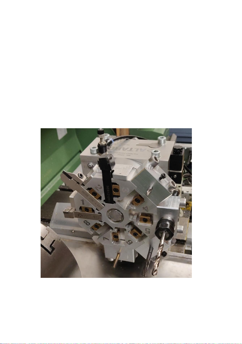
2.2. TOOLS ATTACHEMENT ....................................................- 4-
2.3. ATTACHING OF PRESSURE AIR AND COOLING FLUID .................- 6-
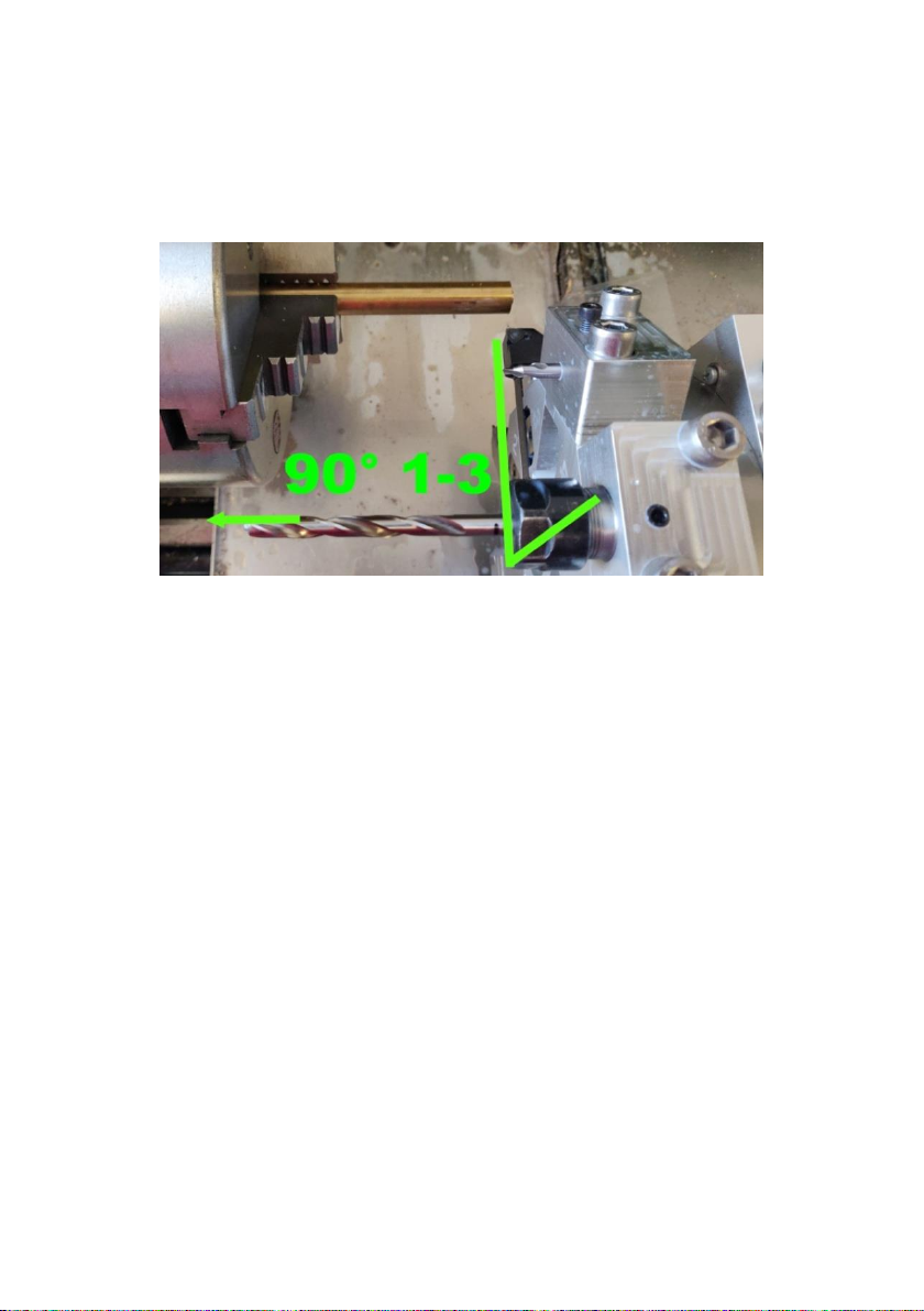
2.4. MANUAL TOOL POSITIONING ............................................- 9-
3. AUTOMATIC CONTROL................................................... - 10 -
3.1. WIRING CONNECTIONS .................................................- 10 -
3.2. SOFTWARE PRAPARATION ..............................................- 12 -
3.3. CONTROL MACROS ......................................................- 14 -
3.4. COOLANT CONTROL .....................................................- 15 -
3.5. OPERATION ON CNC LATHE ...........................................- 16 -
3.6. RUNNING THE PROGRAM FOR THE FIRST TIME .....................- 17 -
4. MAINTENANCE INSTRUCTIONS ...................................... - 18 -
4.1. LUBRICATION .............................................................- 18 -
4.2. CLEANING .................................................................- 18 -
5. TROUBLESHOOTING....................................................... - 19 -
5.1. ERRORS ....................................................................- 19 -
5.2. AFTER TURNING,THE HEAD DOES NOT RETRACT...................- 21 -
5.3. IMPAIRED MACHINING ACCURACY ....................................- 21 -
5.4. COOLANT SUPPLY IS INTERRUPTED ...................................- 21 -
5.5. THE HEAD EXTENDS BUT DOES NOT ROTATE ........................- 21 -
6. TECHNIC DATA ............................................................... - 24 -
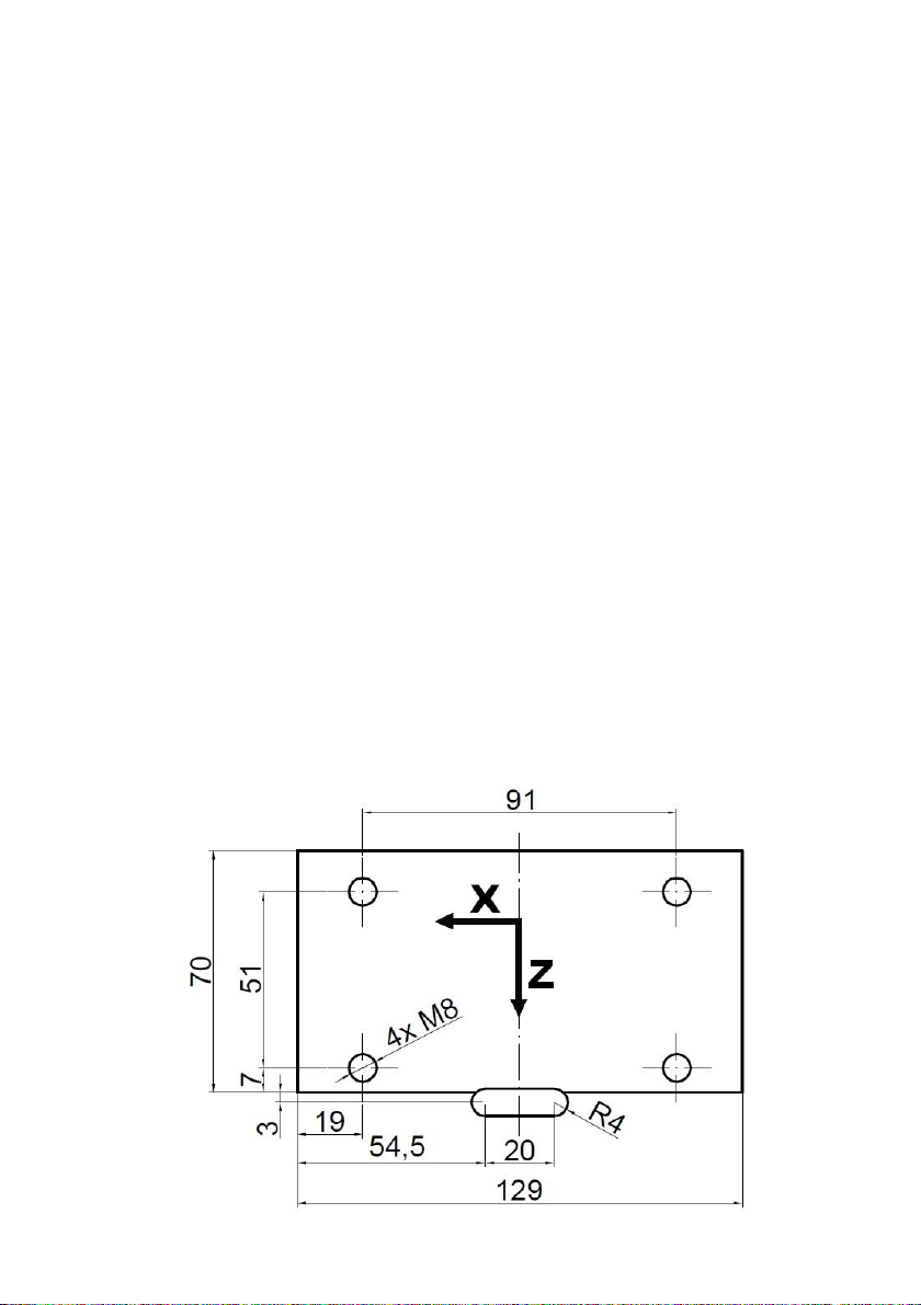
7. DRAWINGS..................................................................... - 25 -
7.1. TOOL CUBE................................................................- 25 -
7.2. COOLANT PLATE ..........................................................- 26 -
8. WARRANTY CONDITIONS ............................................... - 27 -

- 2 -
SAFETY INSTRUCTIONS:
Only a person familiar with this manual can operate
the turret tool head. It is a semi-professional device
and needs to be under operator supervision during
operation.
Obey workplace safety laws!
Do not interfere with the machining area when
operating the machine.
After removing the cover elements there is a risk of
finger injury between the contact surfaces and in the
inner mechanism.
Do not touch the tool head while rotating, you can
cause it's stop in the intermediate position and it
may become jammed.
1. INTRODUCTION AND DESCRIPTION
Automatic turret tool head ALTAROS is designed
for quick exchange of eight tools on a classic or
CNC lathe. Positioning of tools is performed by
a solenoid valve controlled manually or by
a program. The automatic tool head is primarily
intended for the Mach3 program.
The patented pneumatic mechanism guarantees
high rigidity and long-term repeatability in accuracy.
While maintaining compact dimensions and ease of
use.
It can operate with coolant supply directly to the
cutting edge of the tool during machining.

- 3 -
Tools are rotating clockways and every position
have its number.
2. PREPARATION
2.1.Attaching to the lathe
First, remove the original tool holder on the lathe
slide. Then it is necessary to manufacture a plate
for attachment to the original slide to get the right
high so that the axis of the turret head is at the level
of the main axis of the lathe. The plate must have
threaded holes M8 and recesses as shown in
FIG. 1. In the direction of the Z axis, the overhang of
the mounting plate is suitable for attachment to the
slide. There must be no overhang towards the
chuck to allow rotation. The axis height of the
automatic turret head is 64.5 mm. After settling,
check that the head is axially and horizontally
identical to the lathe. Tighten screws on the
attachment plate and turret head base.
FIG. 1 Attachment to the slide

- 4 -
2.2.Tools attachement
Attach elongated tools, such as turning tools, to the
rectangular cutouts from the front side. It is highly
recommended to shorten the length of these tools to
a minimum, reducing the load on the turret head
and increasing rigidity and accuracy. Grooves are
made for tools with a height of 12 mm, larger tools
need to be milled to this size. After inserting the tool
into the groove, insert the pressure wedge into the
side recess and tighten it with the screw.
If the tool hold in place when changing tools after
loosening the screw. If necessary, tap the tool out
with a rubber mallet.
FIG. 2 Attached tools

- 5 -
Tools in direction of main axis, such as drills, are
attached to the tool cubes into holes or chucks
(technical documentation in the attachment). To
attach them to the tool head, press the bottom of
the cube onto the flat surface on side of the head so
that it fit into the cutout. Then push the cube as far
as it will go to the rear wall. Hold the cube down and
back and tighten the retaining screws with
suggested momentum of 8 Nm.
It is not good to place a long tool in the main axis
direction (drill) next to the machining tool in direction
of X axis or a short one. The instruments are at an
angle of 45 °, in case of poorly selected tool
position, a collision of tool (drill) with a material
or a chuck can occur. The same applies to any
tool with significantly different lengths, especially
when machining near the chuck.
FIG. 3 Wrong placement of tools

- 6 -
It is right to place the long tool two positions
away from the short one.
We recommend you to place a combined facing and
roughing tool on the first position, grooving second
and the threading third, which do not need to be
removed and can be permanently mounted.
Calibrate the other tools relative to roughing tool.
(FIG. 2).
2.3.Attaching of pressure air and cooling fluid
Connect the source of clean filtered compressed air
to the quick coupling to the solenoid valve with a 6
mm hose. The maximum operating pressure is 72
PSI (5 bar), we strongly recommend the use of a
pressure in the range of 58 to 60 PSI (4-4.2 bar), if
higher pressure is used, damage and rapid wear of
the turret head can occur. Use a pressure regulator
for the correct inlet pressure.
On the top side there is a valve that serves to
supply coolant to the tools. The fluid is passed
FIG. 4 Correct placement of tools

- 7 -
through a 6 mm hose. The upper valve wheel
adjusts the required fluid flow and the lower locks
the selected setting. A thin sheet metal plate is used
to direct the liquid onto the frontal tools, before use
drill a 1.5 - 2 mm hole as needed. It must reach the
inner channel. It is necessary to choose the correct
angle and direction of the hole so that the fluid flow
is directed to the tool edge. Minor variation can be
adjusted by slightly turning this plate. In the case of
tools mounted in the side cubes, it is possible to drill
a 3.5 mm hole from the drawing to the required
depth and drill small hole in the right direction from
the front side, after connecting those two holes the
coolant can be fed through the created channel.
A simpler method, eg for drills of different lengths, is
to supply coolant with a nozzle located above the
workpiece, where it is fed by a branch from the
hose.
FIG. 5 Tool jigs with tools

- 8 -
FIG. 6 Connecting scheme

- 9 -
2.4.Manual tool positioning
Before each tool positioning, move the slide away
from the workpiece in both axes to avoid a collision
of longer tool with the workpiece. In the case of drill
bits and front blades, note that when exchanging
the tools, the tool head extends of 7 mm! The
current tool is replaced by manual activation of the
solenoid valve mounted on the leftside. Pressing
and holding the button on the valve extends the tool
head and rotates it one position clockwise. After
stopping in a new position, release the button and
the tool head snaps back into place where it locks.
FIG. 7 Manual positioning

- 10 -
3. AUTOMATIC CONTROL
3.1.Wiring connections
The turret head in automatic mode is controlled by
the opto-isolated breakout board with the parallel
port and two relays. The power source have to
converts the mains voltage to 12V. The signals from
the computer are routed via a parallel port to the
isolated board, which is powered from the 12V
power supply. The two wires controlling the solenoid
valve are connected to the relay terminal, pin (14)
and ground (GND), using the second relay with pin
(1) and ground (gnd) you can be switching the
coolant pump see chapter 3.4..
Other conductors lead from the inductive position
sensor inside, which is connected by a black
conductor to pin (12), brown to a 12 V source and
blue to ground (GND).
For our needs we use and can recommend the
SmoothStepper 5 V HW interpolator with Ethernet
cable connection, which connects to a parallel port
with the isolated board.
Diagrams of CNC IO Board connection from
www.cncshop.cz .

- 11 -
FIG. 8 Connecting of the board

- 12 -
3.2.Software praparation
The Mach 3 program is designed as a control
program, which has to be installed on the control
computer. After successful installation, the control
electronic can be connected to the computer. The
new device can be found via Control Panel. You
have to select the active pins in the program. Under
the Config, Ports and Pins (FIG. 9), on the Input
Signals tab, on the Input #4 line select Eneable,
Port # change to 1, Pin Number to 12 and Aply. In
Output Signals, on the Output #6 line select
Eneable, Port # change to 1, Pin Number to 14 and
Aply. (FIG. 11).
FIG. 9 Ports and Pins

- 13 -
Select the Diagnostic button on the Mach3 front
page. With the correct setting and wiring, the
indicator light below the Inputs of Active 4 should
glow green on the odd-numbered positions of the
tool head. When the head-rotation program is
running, the red indicator light under Output 6
should flash when the signal is send to the valve.
FIG. 10 Input setting
FIG. 11 Output setting

- 14 -
3.3.Control macros
To control the automatic turret head directly from
the G-code, it is necessary to download to the
computer and correctly place the control macro, ie
the file with the control commands for the tool
change.
You can find it on the website:
https://www.altaros.cz/M6Start.zip. Download and
extract the file M6Start.m1s and save it to the
Mach3 folder under the macros into the sub-file you
are using to control. An example of pathname when
operating via Mach3Turn:
(C:\Mach3\macros\Mach3Turn). For this macro,
refer to TXXYY M6 in the program, where XX
replaces tool position on turret head and YY tool
number in tool table in program example T0521 M6
FIG. 12 Diagnostic window

- 15 -
(tool on head position No. 5, in table under No. 21,
rotation start).
3.4.Coolant control
If a coolant supply is required, a small pump can be
connected. During installation, the device must not
be live and work may be carried out by a skilled
person. The pump feed wire is cut in two and the
ends are conected to the second relay on the
isolated board, similar to the solenoid valve. The
program then needs to determine the output signal
that controls the relay. The relay is located under
pin number 1. For automatic switching of the cooling
fluid supply, find the Spindle Setup tab under the
Config folder under Ports and Pins in Mach3. In the
Flood Mist Control area, the Disabled checkbox
must remain unchecked and select an output
number between 1-6 for the Flood. In our case,
number 3was selected.
FIG. Flood setting

- 16 -
On the Output Signals tab, find the line where is
the Output with selected number (Output # 3), click
on Eneable, overwrite Port # to 1and Pin Number
to 1.
For fluid switching, the M8 and M9 codes are used,
where M8 starts the coolant supply and M9
switches off, liquid shutdown is required during each
tool change!
3.5.Operation on CNC lathe
When starting Mach3 for machining, you must enter
# 1into the Tool No. box, Tool No. determines the
FIG. 14 Output signals
-
flood

- 17 -
position on the tool head in the range of 1-8. Use
the Tool Adjust button for any tool changes in the
tool table to enter the tool number from the tool
table into Current Tool box. Once you've finished
editing, return to the Cycle environment, manually
positioning to Tool 1 and override Tool No. to
number 1. Before the automatic tool change, the
slide must be driven far enough away from the
workpiece in both axes to avoid tool collision with
the workpiece. In the case of drill bits and front
blades, note that when turning the tools, the turret
head extends of 7 mm. When turning back to the
first position, the length of all tools must be taken
into account.
First, you need to calibrate the programmed point
for tool # 1 and then for each additional tool and
write it to the tool table for use in the program.
3.6.Running the program for the first time
It is advisable to go through the program and check
the tool layout and retraction distance values for
safe tool exchange before starting. The first time
you start a new program, you need to be ready to
stop the program because a code error could cause
a collision. For the same reason, it is recommended
that you hold the rotating part of the turret head on
top of the side in the event that it turns differently
than the programmer planned.

- 18 -
4. MAINTENANCE INSTRUCTIONS
4.1.Lubrication
In case of a change in usual mechanism behavior, it
may be necessary to lubricate the internal
mechanism. Unscrew the cover plate on the back.
And apply silicone oil inside.
4.2.Cleaning
Before attaching the tools it is necessary to clean
the contact surfaces so that the dirt does not deflect
the tool and the accuracy is not impaired.
Deterioration in machining accuracy can cause
clogging of the tapered seating surfaces with solid
contaminants, such as metal shavings, that would
come under the cover plate. If this less likely
situation occurs. The space between the contact
surfaces must be cleaned. First unscrew the
stainless steel plate covering the gap between the
turret head and the mechanism body. Disconnect
the air supply to the valve to eject the turret head.
Blow out the gap with compressed air. After
cleaning, re-insert the air supply and fasten the
cover plate. This should be fixed in the same way
as before dismantling. First leave the screws loose
and tighten them gradually while pressing the plate
to the rotating part of the turret head so that no
large gaps remain for shavings penetrating inside,
but at the same time the rotating head should not
rub against the cover.

- 19 -
5. TROUBLESHOOTING
5.1.Errors
If the program is stopped and an error message is
displayed, the program has evaluated that the
instructions have been misspelled, or the rotating
head has behaved unusualy. Error messages with
timestamps can be found in the Diagnostic tab on
the Home screen under the history button (FIG. 16)
appearsin the LastErrors window. After program
stops, press the Reset button before other actions.
FIG. 15 T
apered seating surfaces
FIG. 16 Diagnostic
–
History
Table of contents
Popular Industrial Equipment manuals by other brands

Zimmer
Zimmer GSI Series Installation and operating instructions

Conductix-Wampfler
Conductix-Wampfler 0832 operating instructions

Siemens
Siemens 7KM9200-0AD00-0AA0 operating instructions

Greenheck
Greenheck ESD-202 Installation, operation and maintenance manual

PushCorp
PushCorp AFD1240 manual

NARGESA
NARGESA H1 Instruction book

SINTERIT
SINTERIT SANDBLASTER SLS Original manual

Rockwell Automation
Rockwell Automation Allen-Bradley FLEX installation instructions

HEIDENHAIN
HEIDENHAIN ERP 880 Mounting instructions

CM
CM BEAM CLAMP operating instructions

Panasonic
Panasonic CM202 Series Maintenance manual

Endress+Hauser
Endress+Hauser Stamoclean CAT430 operating instructions