5 of 6
749-50092
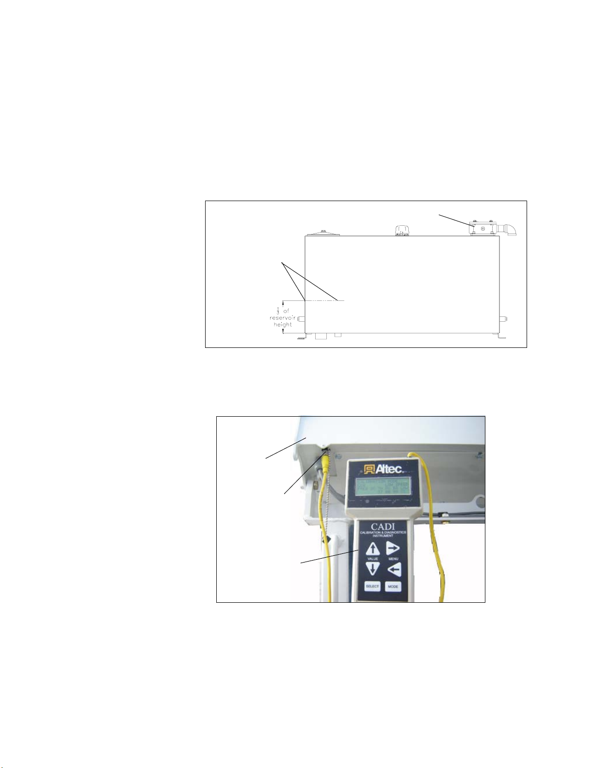
Figure 7 - Boom Angle Indicator
4. Set the low speed/standard switch to Standard on the control panel being used.
Operate with the engine at full RPM.
5. RecordtheMXsettingforthefunctiontobecalibrated(BoomUp/Down,RotationCW/
CCW, Intermediate Boom Extend/Retract, Upper Boom Extend/Retract, Winch In/
Out,orDiggerDig/Clean).ThenchangetheTHandMXsettingsforthisfunctionto00.
ThevaluebuttonontheCADIcanbehelddowncontinuouslyuntilthesettingreaches
00.
6. Operate the hand control and adjust the MX and TH values for the function being
calibrated as described in Steps 6a through 6g.
a. Fully shift and hold the hand control, and increase the MX value slowly until the
functionstartsmoving.
b. Releasethehand control, anddecrease the MXvalue by3 points.
c. Fullyshift and hold the hand control, and checkfor function movement. If the
functionisfullystopped,continuetostepd.Ifthefunctionisnotfullystopped,go
back to step b.
d. IncreasetheMXvalueby1pointevery5secondsuntilthefunctionbeginstocreep,
meaningtooperateat theslowestmovementnoticeable.ForBoomUp/Down,
watchtheliftcylinderrodformovement.Forotherfunctions,comparethemoving
component to a stationary object.
e. Releasethehandcontrol.Subtract15pointsfromtheMXvaluedeterminedinthe
previousstepto obtain therequiredTH setting. Thenadjust the THvalueto this
number.Forexample,ifthefunctionbeginstocreepatMX=42,subtract42-15=27,
and adjust the TH setting to 27.
f. RecordthefinalTHsettingontheCADIValuesSheetortheFieldCADISettings
Guide.
g. Return the MX setting to the value it had before it was changed to 00.
7. RepeatSteps5-6for each directionofeach boom, winch,anddigger function.
8. Proceed to Section 3:Max Out andLow Speed Calibration.
Indicating10-30
Degrees
Section 2
(Continued)