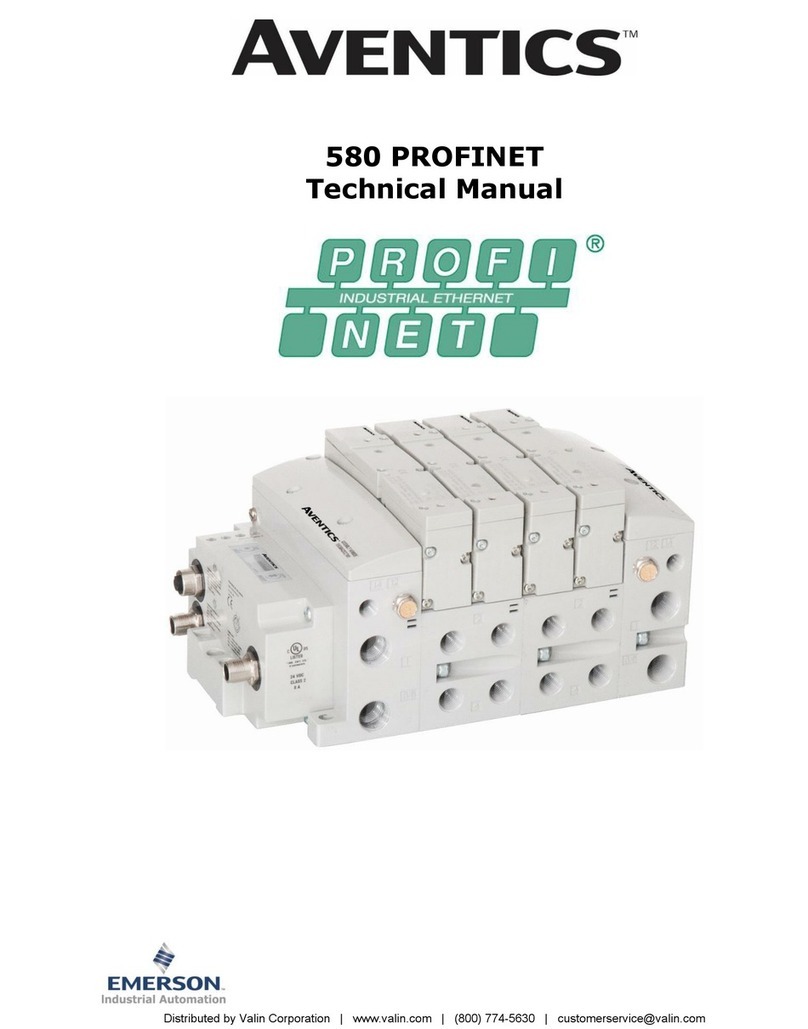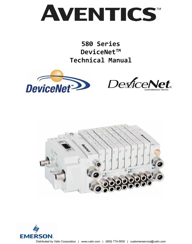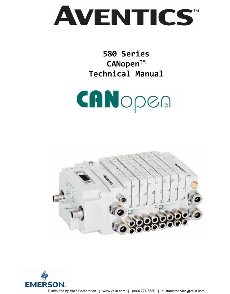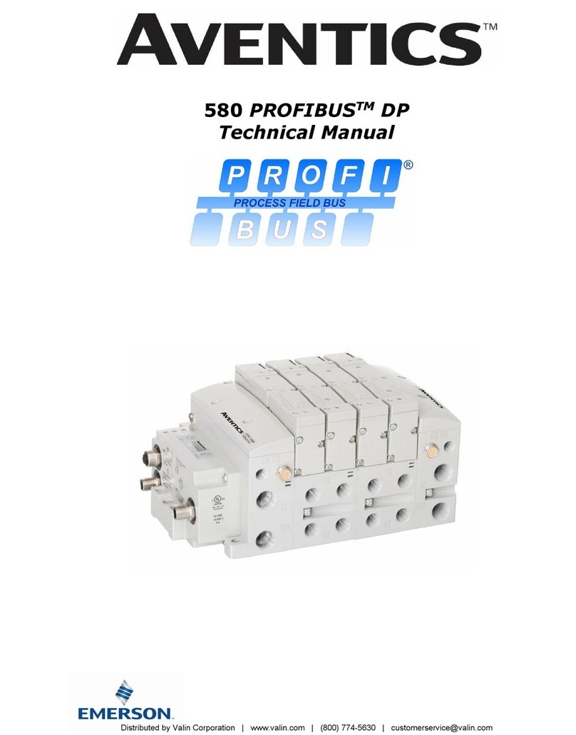
580 CHARM Technical Manual
1-4
TD580CHTM1-12EN 06/2021
Subject to change without notice
www.emerson.com
Table of Contents
PAGE
About CHARM Overview ............................................................................................................................... 1-5
1.1 580 CHARM Features ........................................................................................................................... 1-5
1.2 Cabling ............................................................................................................................................. 1-5
580 CHARM Introduction .............................................................................................................................. 2-6
2.1 Coil Capability ................................................................................................................................... 2-7
2.2 Maximum Coil Capability ..................................................................................................................... 2-8
2.3 Multiple manifold CHARM Cable Sets: ................................................................................................... 2-9
2.4 Pneumatic Valve Manifold ................................................................................................................. 2-10
2.5 Solenoid Coil Connections using Z-BoardTM Technology ........................................................................... 2-11
2.6 Z-Board™ Connectors ........................................................................................................................ 2-12
CHARM Communication Node ...................................................................................................................... 3-13
3.1 CHARM Node Description ................................................................................................................... 3-14
3.2 Connector Pinouts ............................................................................................................................. 3-15
3.3 Chassis Ground ................................................................................................................................ 3-16
3.4 Power Consumption .......................................................................................................................... 3-17
3.5 Valve Power Isolator ......................................................................................................................... 3-18
3.6 580 CHARM Node LED Functions ......................................................................................................... 3-20
3.7 Valve Coil Short Circuit / Open Load Protection ...................................................................................... 3-21
CHARM Node Graphic Display ...................................................................................................................... 4-22
4.1 Bank Address Sub-Menu .................................................................................................................... 4-23
4.2 Model Number .................................................................................................................................. 4-24
4.3 Advanced Settings Menu – Flip Display ................................................................................................ 4-24
4.4 Advanced Settings Menu – Addressing Scheme..................................................................................... 4-25
4.5 36 Coil Optimization .......................................................................................................................... 4-27
4.6 PWM Control (Coils) .......................................................................................................................... 4-28
4.7 Advanced Settings Menu – Parameters ................................................................................................. 4-29
4.8 Factory Defaults ............................................................................................................................... 4-30
4.9 Diagnostic Menu ............................................................................................................................... 4-30
4.10 Coil “Self Test” Mode .......................................................................................................................... 4-31
4.11 Error Messages .................................................................................................................................. 4-32
CHARM Output Configuration ....................................................................................................................... 5-33
5.1 Charm Configuration Options ............................................................................................................. 5-34
CHARM Mapping......................................................................................................................................... 6-35
6.1 Outputs (Valves) .............................................................................................................................. 6-35
6.2 Output Mapping ................................................................................................................................ 6-35
6.3 Mapping Example for 36 Coils ............................................................................................................. 6-36
6.4 Mapping Example for 48 Coils ............................................................................................................. 6-37
6.5 Mapping Example for 64 Coils ............................................................................................................. 6-38
Mapping Example for 64 Coils Cont. .................................................................................................... 6-39
6.6 Mapping Example for 96 Coils ............................................................................................................. 6-40
6.7 Commissioning CHARM Node with DeltaV Software ................................................................................ 6-42
6.8 580 CHARM Module Changes .............................................................................................................. 6-47
Firmware Upgrade ...................................................................................................................................... 7-49
7.1 Procedure to upgrade the 580 Charm node firmware ............................................................................. 7-49
Appendix................................................................................................................................................... 8-52
8.1 System Specifications ........................................................................................................................ 8-52
8.2 Factory Default Settings .................................................................................................................... 8-52
8.3 Troubleshooting ................................................................................................................................ 8-53
8.4 Glossary of Terms ............................................................................................................................. 8-53
8.5 Technical Support ............................................................................................................................. 8-53
Distributed
by
Valin
Corporation
|
www.valin.com
|
(800)
774-5630
|
[email protected]