ALTENERGY POWER SYSTEM Inc. YC500I Instruction Manual

Installation / User Manual
Rev 1.2
ALTENERGY POWER SYSTEM Inc.
www.APsystems.com
APsystems Europe
Cypresbaan 7, 2908LT, Capelle aan den Ijssel, The Netherlands
TEL: 0031-10-2582670 EMAIL:info@altenergy-power.com
© All Rights Reserved (For South Africa )
APsystems YC500I
Photovoltaic Grid-connected Microinverter

APsystems YC500I Installation/User Manual
1
Table of Contents
Important Safety Instructions..............................................................................................................2
Safety Instructions................................................................................................................................................ 2
Radio Interference Statement.............................................................................................................................. 3
Symbols replace words on the equipment, on a display,.....................................................................................4
or in manuals.........................................................................................................................................................4
APsystems Microinverter System Introduction.................................................................................. 5
APsystems Microinverter YC500I Introduction...................................................................................7
APsystems Microinverter System Installation.................................................................................... 8
Additional Installation components from APsystems..........................................................................................8
Required Parts and Tools from you...................................................................................................................... 8
Installation Procedures......................................................................................................................................... 9
Step 1 - Position the AC bus cable................................................................................................................ 9
Step 2 - Install the AC branch circuit junction box....................................................................................... 9
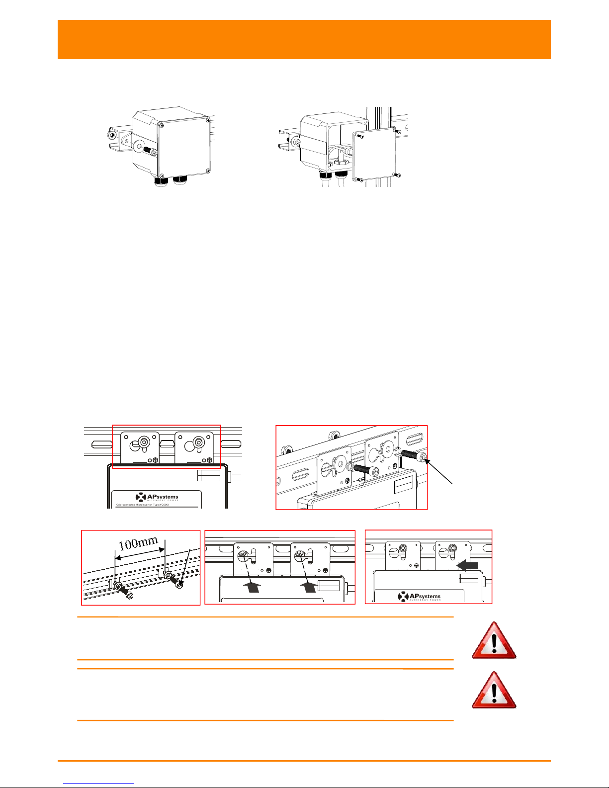
Step 3 - Attach the APsystems Microinverters to the racking or the PV module frame..............................9
Stpe 4 - Connect the APsystems microinverter to AC bus cable................................................................ 10
Step 5 - Install a AC bus protective end cap at the end of AC bus cable....................................................11
Step 6 - Connect APsystems Microinverters to the PV Modules................................................................11
Step 7 - Complete the APsystems installation map....................................................................................12
Step 8 - Place a Warning Notice................................................................................................................. 13
APsystems microinverter system operating instructions................................................................. 14
Troubleshooting................................................................................................................................. 15
Status Indications and Error Reporting...............................................................................................................15
Start up LED.................................................................................................................................................15
Operation LED............................................................................................................................................. 15
Other Faults.................................................................................................................................................15
Troubleshooting a non-operating APsystems Microinverter............................................................................. 16
Maintenance...................................................................................................................................... 16
Replace a microinverter.....................................................................................................................17
Technical Data.................................................................................................................................... 18
APsystems YC500I Microinverter Datasheet...................................................................................................... 19
Wiring Diagram.................................................................................................................................. 20
Sample Wiring Diagram - Single Phase...............................................................................................................20
Sample Wiring Diagram - Three Phase............................................................................................................... 21

APsystems YC500I Installation/User Manual
2
Important Safety Instructions
This manual contains important instructions to follow during installation
and maintenance of the APsystems Photovoltaic Grid-connected Inverter
(Microinverter). To reduce the risk of electrical shock and ensure the safe
installation and operation of the APsystems Microinverter, the following
symbols appear throughout this document to indicate dangerous conditions
and important safety instructions.
Specifications subject to change without notice - please ensure you are using
the most recent update found at www.APsystems.com
WARNING: This indicates a situation where failure to follow
instructions may cause a serious hardware failure or personnel
danger if not applied appropriately. Use extreme caution when
performing this task.
NOTE: This indicates information that is important for optimized
microinverter operation. Follow these instructions closely.
Safety Instructions
Do NOT disconnect the PV module from the APsystems Microinverter
without first disconnecting the AC power.
Only qualified professionals should install and/or replace APsystems
Microinverters.
Perform all electrical installations in accordance with local electrical
codes.
Before installing or using the APsystems Microinverter, please read
all instructions and cautionary markings in the technical documents
and on the APsystems Microinverter system and the solar-array.
Be aware that the body of the APsystems Microinverter is the heat
sink and can reach a temperature of 80°C. To reduce risk of burns,
do not touch the body of the Microinverter.
Do NOT attempt to repair the APsystems Microinverter. If it fails,
contact APsystems Customer Support to obtain an RMA number and
start the replacement process. Damaging or opening the APsystems
Microinverter will void the warranty.
Caution!
The external protective earthing conductor is connected to the inverter
protective earthing terminal through AC connector.
When connecting, connect the AC connector first to ensure the inverter
earthing then do the DC connections.
When disconnecting, disconnect the AC by opening the branch circuit
breaker first but maintain the protective earthing conductor in the
branch circuit breaker connect to the inverter ,then disconnect the DC
inputs.
In any circumstance, do not connect DC input when AC connector is
unplugged.
Please install isolation switching devices on the AC side of the inverter.
WARNING
SYMBOL
NOTE
SYMBOL

APsystems YC500I Installation/User Manual
3
Important Safety Instructions
Radio Interference Statement
CE EMC Compliance:The equipment can comply with CE EMC, which
are designed to protect against harmful interference in a residential
installation. The equipment could radiate radio frequency energy and this
might cause harmful interference to radio communications if not following
the instructions when installing and using the equipment. But there is no
guarantee that interference will not occur in a particular installation. If
this equipment causes harmful interference to radio or television reception,
the following measures might resolve the issues:
A) Relocate the receiving antenna and keep it well away from the
equipment.
B) Consult the dealer or an experienced radio / TV technical for help.
Changes or modifications not expressly approved by the party responsible
for compliance may void the user’s authority to operate the equipment.

APsystems YC500I Installation/User Manual
4
Important Safety Instructions
Symbols replace words on the equipment, on a display,
or in manuals
Trademark
Caution, risk of electric shock
Caution, hot surface
Refer to the operating instructions
Qualified
personnel
Person adequately advised or supervised by an electrically skilled person
to enable him or her to perceive risks and to avoid hazards which
electricity can create. For the purpose of the safety information of this
manual, a "qualified person" is someone who is familiar with requirements
for safety, refrigeration system and EMC and is authorized to energize,
ground, and tag equipment, systems, and circuits in accordance with
established safety procedures. The inverter and endues system may only
be commissioned and operated by qualified personnel.

APsystems YC500I Installation/User Manual
5
APsystems Microinverter System Introduction
The APsystems Microinverter is used in utility-interactive grid-tied
applications, comprised of three key elements:
APsystems Microinverter
APsystems Energy Communication Unit (ECU)
APsystems Energy Monitor and Analysis (EMA) web-based
monitoring and analysis system
Figure 1

APsystems YC500I Installation/User Manual
6
APsystems Microinverter System Introduction
This integrated system improves safety; maximizes solar energy harvest;
increases system reliability, and simplifies solar system design, installation,
maintenance, and management.
APsystems Microinverters maximize PV energy production
Each PV module has individual Maximum Peak Power Tracking (MPPT)
controls, which ensures that the maximum power is exported to the utility
grid regardless of the performance of the other PV modules in the array.
When PV modules in the array are affected by shade, dust, orientation,
or any situation in which one module underperforms compared with the
other units, the APsystems Microinverter ensures top performance from
the array by maximizing the performance of each module within the array.
More reliable than centralized or string inverters
The distributed APsystems Microinverter system ensures that no single
point of system failure exists across the PV system. APsystems Microin-
verters are designed to operate at full power at ambient outdoor temper-
atures of up to 149°F (65°C). The inverter housing is designed for outdoor
installation and complies with the IP65 environmental enclosure rating.
Simple to install
You can install individual PV modules in any combination of module
quantity, orientation, type, and power rate. The Ground wire (PE)
of the AC cable is connected to the chassis inside of the Microi-
nverter, eliminating the installation of grounding wire.
Smart system performance monitoring and analysis
The APsystems Energy Communication Unit (ECU) is installed by simply
plugging it into any wall outlet and providing an Ethernet or Wi-Fi conn-
ection to abroadband router or modem. After installing the ECU, the full
network of APsystems Microinverters automatically reports to the APsy-
stems Energy Monitor and analysis (EMA) web server. The EMA software
displays performance trends,informs you of abnormal events, and controls
system shutdown when it is needed. (See ECU manual for instructions.)

APsystems YC500I Installation/User Manual
7
APsystems Microinverter YC500I Introduction
The APsystems YC500I Microinverters connect with the single-phase
grid, and can also use multiple APsystems Microinverters in the form of
single-phase grid to achieve three-phase grid, and operate with most 60
and 72 cell PV modules. For more information, please see the Technical
Data page (p.18) of this manual, or sign in APsystems website to obtain
a solar panel list which can match with APsystems Microinverters:
www.APsystems.com
Model
Number
AC grid
PV Module
Max. #
Per branch
Module Connector
YC500I
50Hz/230V
60,72 Cell
7 for 20A
breaker
MC-4 Type or Customize

APsystems YC500I Installation/User Manual
8
APsystems Microinverter System Installation
A PV system using APsystems Microinverters is simple to install. Each
Microinverter easily mounts on the PV racking, directly beneath the PV
module(s). Low voltage DC wires connect from the PV module directly
to the Microinverter, eliminating the risk of high DC voltage.
Installation MUST comply with local regulations and technical rules.
Special Statement! An AC GFCI device should not be used to protect the
dedicated circuit to the APsystems microinverter even though it is an outside
circuit. None of the small GFCI devices (5mA-30 mA) are designed for back
feeding and will be damaged if back feed. In a similar manner, AC AFCIs
have not been evaluated for back feeding and may be damaged if back feed
with the output of a PV inverter.
WARNING: Perform all electrical installations in accordance with
localelectrical codes.
WARNING:Be aware that only qualified professionals should install
and/or replace APsystems Microinverters.
WARNING: Before installing or using an APsystems Microinverter,
please read all instructions and warnings in the technical documents
and on the APsystems Microinverter system itself as well as on the
PV array.
WARNING: Be aware that installation of this equipment includes
the risk of electric shock.
WARNING: Do not touch any live parts in the system, including the
PV array, when the system has been connected to the electrical grid.
NOTE: Strongly recommend to install Surge protection Devices in
the dedicated meter box.
Additional Installation components from APsystems
AC bus protective end cap (sold separately)
Sealing caps (sold separately)
Required Parts and Tools from you
In addition to your PV array and its associated hardware, you will need
the following items:
An AC connection junction box
Mounting hardware suitable for module racking
Sockets and wrenches for mounting hardware
Continuous grounding conductor and grounding washers
A Phillips screwdriver
A torque wrench

APsystems YC500I Installation/User Manual
9
Installation Procedures
Step 1 - Position the AC bus cable
Step 2 - Install the AC branch circuit junction box
Figure 2
a. Install an appropriate junction box at a suitable location on the PV
racking system ((typically at the end of a branch of modules).
b. Connect the open wire end of the AC bus cable into the junction
box using an appropriate gland or strain relief fitting.
c. Wire the conductors: L - BROWN; N - BLUE; PE - YELLOW GREEN.
d. Connect the AC branch circuit junction box to the point of utility
interconnection.
Step 3 - Attach the APsystems Microinverters to the racking or
the PV module frame
a. Mark the location of the Microinverter on the rack, with respect to
the PV module junction box or any other obstructions.
b. Mount one Microinverter at each of these locations using hardware
recommended by your module racking vendor.
Option 1:
A
B
Figure 3
Option 2:
Figure 4
WARNING: Prior to installing any of the microinverters, verify
that the utility voltage at the point of common connection matches
the voltage rating on microinverter label.
WARNING: Do not mount the Microinverter in a location that
allows exposure to direct sunlight. Allow a minimum of 3/4’’(1.5cm.)
between the roof and the bottom of the Microinverter to allow proper
air flow.
M8
M8

APsystems YC500I Installation/User Manual
10
Installation Procedures
Stpe 4 - Connect the APsystems microinverter to AC bus cable
Figure 5
Best Practice: Use the Withdrawal Tool of AC Bus to split the connectors.
a. Check the Microinverter technical data page(p.18) for the maximum
allowable number of Microinverters on each AC branch circuit.
b. Plug the AC connector of the Microinverter into the AC bus
c. Install a AC bus protective end cap on the open AC connector of the last
Microinverter in the AC branch circuit.
AC connector interface as follows.
Figure 6
Cover any unused connectors with sealing caps to protect the connectors.
Figure 7
WARNING: Do NOT exceed maximum number of Microinverters
in an AC branch circuit, as displayed on the Technical Data page
(p.18) of this manual.
L
PE
N

APsystems YC500I Installation/User Manual
11
Installation Procedures
Step 5 - Install a AC bus protective end cap at the end of AC
bus cable
a. Strip cable jacket. c. Insert the wires into the cable clamps.
b. Insert the cable end into the seal. d. Rotate the nut with 3.3N·m until the
latching mechanism meets the base.
Figure 8
Step 6 - Connect APsystems Microinverters to the PV Modules
Figure 9
The inverter YC500I’s DC input negative pole connect to earthed enclosure
inside the enclosure.
NOTE: When plugging in the DC cables, the Microinverter should
immediately blink green three times. This will happen as soon as
the cables are plugged in and will show that the Microinverter is
functioning correctly. This entire check function will start and end
within 5 seconds of plugging in the unit, so pay careful attention to
these lights when connecting the DC cables.
WARNING: Double check to make sure all of the AC and DC wiring
has been correctly installed. Ensure that none of the AC and/or DC
wires are pinched or damaged. Make sure that all of the junction
boxes are properly closed.
NOTE: About A and B Sides corresponding the location of modules,
EMA registration show acquiesce in this installation. if there are
different connection methods, please email the detail installation
drawings to us to register, or the A, B Sides corresponding component
location will not correspond to the EMA position.
Nut
Seal
Body

APsystems YC500I Installation/User Manual
12
Installation Procedures
Step 7 - Complete the APsystems installation map
Fill in the APsystems Registration Cards, which provide system information
and the installation map. Feel free to provide your own layout if a larger or
more intricate installation map is required. The layout map provided is
designed to accomodate labels in vertical or horizontal orientation to meet
all the field PV connections.
a. Each APsystems Microinverter has removable serial number labels.
Peel labels off, affix one to the respective location on the APsystems
installation map, and fill in A,B in the label below (as figure12)
according to the layout on the roof (as figure 11). Then affix another
label to the PV module frame which is easy to see. The warranty cards
can obtain from the appendix of this manual or APsystems website
www.APsystems.com
b. Fill the warranty cards and email to APsystems at
emasupport@altenergy-power.com
c. APsystems will create the EMA account and email you the account
information. Then you can use the EMA website to view detailed
performance of your PV system. You can learn more information on
energy monitoring and analysis system from APsystems website
www.APsystems.com
A
B
Figure 10
Figure 11

APsystems YC500I Installation/User Manual
13
Installation Procedures
1 2 34 5 6 7 89 10 11 12 13 14 15 1716 18 19 20 2221
APsystems Microinverter&Energy Communication Unit
Warranty Card
The APsystems Installation Map is a diagram of the physical location of each microinverter in your PV installation.
Each APsystems microinverter has a removable serial number label located on the mounting plate. Pee l the label
and affix it to the respective location on the APsystems installation map.
Installation Map Template
To register your APsystems microinverter, please mail this warranty registration card to: emasupport@altenergy-power com.
B A B A B A
Figure 12
NOTE: 1. The layout of the inverters' serial numbers on the warranty
card is only suitable for general arrangement.
2. Step 1~7 can be done in any order..
3. Warranty card is located in Appendix last page of this manual.
4. You can use Scanning Gun or mobile phone to scan the
serial numbers on the map when set ECU (see ECU manual).
Step 8 - Place a Warning Notice
A warning notice shall be placed in such a position that any person gaining
access to live parts will be warned in advance of the need to isolate those
live parts from all points of supply. Special attention should be paid that the
power supply, measuring circuits (sense lines) and other parts may not be
isolated from the network when the switch of the interface protection is open.
As a minimum, warning labels shall be placed:
On the switchboard (DNO panel and consumer unit) that has the
micro-generator connected to it;
On all switchboards in between the consumer unit and the micro-
generator itself;
On, or in the micro-generator itself;
At all points of isolation for the micro-generator.
Figure 13

APsystems YC500I Installation/User Manual
14
APsystems microinverter system operating instructions
To operate the APsystems microinverter PV system:
1. Turn ON the AC circuit breaker on each microinverter AC branch
circuit.
2. Turn ON the main utility-grid AC circuit breaker. Your system will
start producing power after a two-minute waiting time.
3. The units should start blinking green every 2 seconds five minutes
after turning on the AC circuit breaker. This means they are producing
power normally, but have not yet connected to the ECU. After the ECU
has been plugged in and acknowledges the Microinverters, they will
start to blink green every 10 seconds.
4. Plug in the ECU and follow the instructions according to the manual
for the ECU.
5. The APsystems Microinverters will start to send performance data over
power line to the ECU. The time required for all the Microinverters in the
system to report to the ECU will vary with the number of Microinverters
in the system. You can verify proper operation of the APsystems Microinverters
via the ECU. See the ECU Installation and Operation Manual for more
information.
NOTE: Once AC power is applied, about 0.1A current and 25VA(W)
power for each microinverter may be measured with a meter. This
Current and Power are Reactive. The inverters ARE NOT operating.
After an over 60s waiting time, the inverters will start operation.

APsystems YC500I Installation/User Manual
15
Troubleshooting
Qualified personnel can use the following troubleshooting steps if the
PV system does not operate correctly:
Status Indications and Error Reporting
Start up LED
One quick red light followed by three short green blinks when DC power
is first applied to the Microinverter indicates a successful Microinverter
startup.
Operation LED
Flashing Slow Green (10 sec. gap) - Producing power and communicating
with ECU
Flashing Fast Green (2 sec. gap) - Producing power and not
communicating with ECU over 60mins
Flashing Red - Not producing power
Steady Red - Electrode assembly ground fault protection
Other Faults
All other faults are reported to the ECU. Refer to the ECU
Installation and Operation Manual for a list of additional faults
and troubleshooting procedures.
WARNING: Only qualified personnel should directly handle the
APsystems microinverter.
WARNING: Never disconnect the DC wire connectors under
load. Ensure that no current is flowing in the DC wires prior to
disconnecting. An opaque covering may be used to cover the
module prior to disconnecting the module.
WARNING: Always disconnect AC power before disconnecting
the PV module wires from the APsystems microinverter. Either
disconnecting by the appropriate AC circuit breaker or unplugging
the first AC connector of the first Microinverter in a branch circuit
is suitable as a means of disconnection.
WARNING: The APsystems microinverter is powered by PV module
DC power. AFTER disconnecting the DC power, when reconnecting
the PV modules tothe Microinverter, be sure to watch for the three
short LED flashes.

APsystems YC500I Installation/User Manual
16
Troubleshooting
Troubleshooting a non-operating APsystems Microinverter
There are two possible overall areas of trouble:
A. The Microinverter itself may be having problems.
B. The Microinverter itself is working fine but it is having trouble
communicating with the ECU. The items below refer to Microinverter
issues, not communication issues (addressed in the ECU manual).
A quick way to tell whether the issue is the Microinverter or a
communication problem with the ECU:
1. Diagnosing from the Microinverter: A red light – either blinking
or solid on the Microinverter, or no light at all. No light, or a red light,
means it is definitely a Microinverter problem.
2. Diagnosing from the ECU:
a. No-Data-Display: This is probably a communication issue- not a
Microinverter problem.
b. Problems with erratic display: Data is displayed for some period
and then no data is displayed: most likely a communication issue.
c. 0 watts, or 2 watts: Possibly a Microinverter problem
d. Erratic data display that is not coordinating with data displays
from other units: most likely a Microinverter problem.
To troubleshoot a non-operating APsystems Microinverter, Follow
the steps below in order:
1. Verify the utility voltage and frequency are within ranges shown
in the Technical Data section of this manual.
2. Check the connection to the utility grid. Verify utility power is
present at the inverter in question by removing AC, then DC
power. Never disconnect the DC wires while the microinverter
is producing power. Re-connect the DC module connectors and
watch for three short LED flashes.
3. Check the AC branch circuit interconnection between all the
microinverters. Verify each inverter is energized by the utility grid
as described in the previous step.
4. Make sure that any AC breaker are functioning properly and are
closed.
5. Check the DC connections between the microinverter and the PV
module.
6. Verify the PV module DC voltage is within the allowable range shown
in the Technical Data of this manual.
7. If the problem persists, please call APsystems Customer Support.
WARNING: Do not attempt to repair the APsystems microinverter.
If troubleshooting methods fail, please return the microinverter to
your distributor for replacement.
Maintenance
No need to Maintenance.

APsystems YC500I Installation/User Manual
17
Replace a microinverter
Follow the procedure to replace a failed
APsystems Microinverter
A. Disconnect the APsystems Microinverter from the PV Module, in the
order shown below:
1. Disconnect the AC by turning off the branch circuit breaker.
2. Disconnect the first AC connector in the branch circuit.
3. Disconnect the PV module DC wire connectors from the
microinverter.
4. Remove the Microinverter from the PV array racking.
5. Cover the module with an opaque cover.
B. Install a replacement Microinverter to the rack. Remember to observe
the flashing LED light as soon as the new Microinverter is plugged
into the DC cables.
C. Connect the AC cable of the replacement Microinverter and the
neighboring Microinverter to complete the branch circuit connections.
D. Close the branch circuit breaker, and verify operation of the replacement
Microinverter.

APsystems YC500I Installation/User Manual
18
Technical Data
WARNING: Be sure to verify the voltage and current specifications
of your PV module match with those of the Microinverter. Refer to the
APsystems website www.APsystems.com for a list of approved PV
modules.
WARNING: You must match the DC operating voltage range of
the PV module with the allowable input voltage range of the APsystems
Microinverter.
WARNING: The maximum open circuit voltage of the PV module
must not exceed the specified maximum input voltage of the APsystems

APsystems YC500I Installation/User Manual
19
APsystems YC500I Microinverter Datasheet
Region
South Africa
Model
YC500I-ZA
Input Data (DC)
MPPT Voltage Range
22V-45V
Operation Voltage Range
16V-52V
Maximum Input Voltage
55V
Startup Voltage
22V
Maximum Input Current
10.5A x 2
Maximum DC Short Circuit Current
15A
Output Data (AC)
Maximum Output Power
500W
Nominal Output Voltage
230V
Nominal Output Current
2.17A
Default/Protect Output Voltage Range
195.5V-253V*
Extended/Output Voltage Range
149-278V
Nominal Output Frequency
50Hz
Default/Protect Output Frequency Range
47.5Hz-52Hz*
Extended/Output Frequency Range
45.1-54.9Hz
Power Factor
>0.99
Total Harmonic Distortion
<3%
Efficiency
Max. Inverter Efficiency
95.5%
Night Power Consumption
120mW
Mechanical Data
Operating Ambient Temperature Range
-40 °C to +65 °C
Storage Temperature Range
-40 °C to +85 °C
Dimensions (W x H x D)
221mm X 167mm X 29mm
Weight
2.5kg
AC BUS Maximum Current
20A
Enclosure Rating
IP67
Cooling
Natural Convection – No fans
Wet Locations Classification
For Wet Locations
Pollution Degree Classification
PD3
Relative Humidity Ratings
0-95%
Maximum Altitude Rating
All Data At This Technical Specifications Has Been Tested Under
<2000m
Overvoltage Category
OVC II For PV Input Circuit, OVC III For Mains Circuit
Features & Compliance
Communication(Inverter To ECU)
Power Line Communication
Monitoring
Via EMA** Software
Transformer Design
High Frequency Transformers, Galvanically Isolated
Safety and EMC Compliance
IEC/EN 62109-1; IEC/EN 62109-2;EN61000-6-1; EN61000-6-2;
EN61000-6-3; EN61000-6-4;
Grid Connection Compliance
NRS 097-2-1
Automatic Disconnect
Auto Disconnection Device Integrated
© All Rights Reserved
*Programmable through ECU to meet customer need.
**Energy Management Analysis
Specifications subject to change without notice.
Table of contents
Popular Inverter manuals by other brands

Briggs & Stratton
Briggs & Stratton 7000 Rated Watts Home Standby Generator Operator's manual

Solectria Renewables
Solectria Renewables PVI 6500 Installation and operation manual

SMA
SMA SUNNY BOY STORAGE 2.5 technical information

Sungrow
Sungrow SG80KTL Quick installation guide

Bticino
Bticino M7875A Series manual

Mitsubishi Electric
Mitsubishi Electric 800 Series instruction manual

Apex Digital
Apex Digital APEX-P3-15K user manual

Mastervolt
Mastervolt WHISPER 8 ULTRA installation manual

Sunforce
Sunforce Pro Series 11260 user manual

Western Co
Western Co Leonardo Off-Grid 4kW/3000/48 GE Py user manual

PNI
PNI L500W user manual

KIMO RHVAC Controls
KIMO RHVAC Controls FrigoPack E FU+/12 quick start guide