AlterG M300 Series User manual

1
AlterG Installation Manual 105440 rev C
AlterG Anti-Gravity
Treadmill®
M300 Series
Installation Manual

2
AlterG Installation Manual 105440 rev C
This manual covers installation and service procedures for the following AlterG products for
rehabilitation and fitness applications:
AlterG Anti-Gravity TreadmillM310
AlterG Anti-Gravity TreadmillM320
NOTE: The following symbol is used throughout this manual to call attention to steps or
operational procedures that may directly affect your safety or the safe operation of the
AlterG Anti-Gravity Treadmill. Read and understand these instructions and statements
before servicing the AlterG Anti-Gravity Treadmill.
NOTE: The AlterG Anti-Gravity Treadmill has been tested to IEC medical standards for
electrical safety. It is a Class I, Type B device.
Type B Medical Equipment
RoHS compliant product
IEC 60601-1-1 compliant
IEC 60601-1-2 compliant
IPX-0
AlterG and Anti-Gravity Treadmill are registered trademarks in the US by AlterG, Inc.
AlterG Incorporated
48438 Milmont Drive
Fremont, California 94538
USA
510-270-5369 or email support@alter-g.com
Caution: You may be injured or damage the product if you fail to
follow the procedures and safety tips outlined in this document

3
AlterG Installation Manual 105440 rev C
TABLE OF CONTENTS
Table of Contents ...................................................................................................................... 3
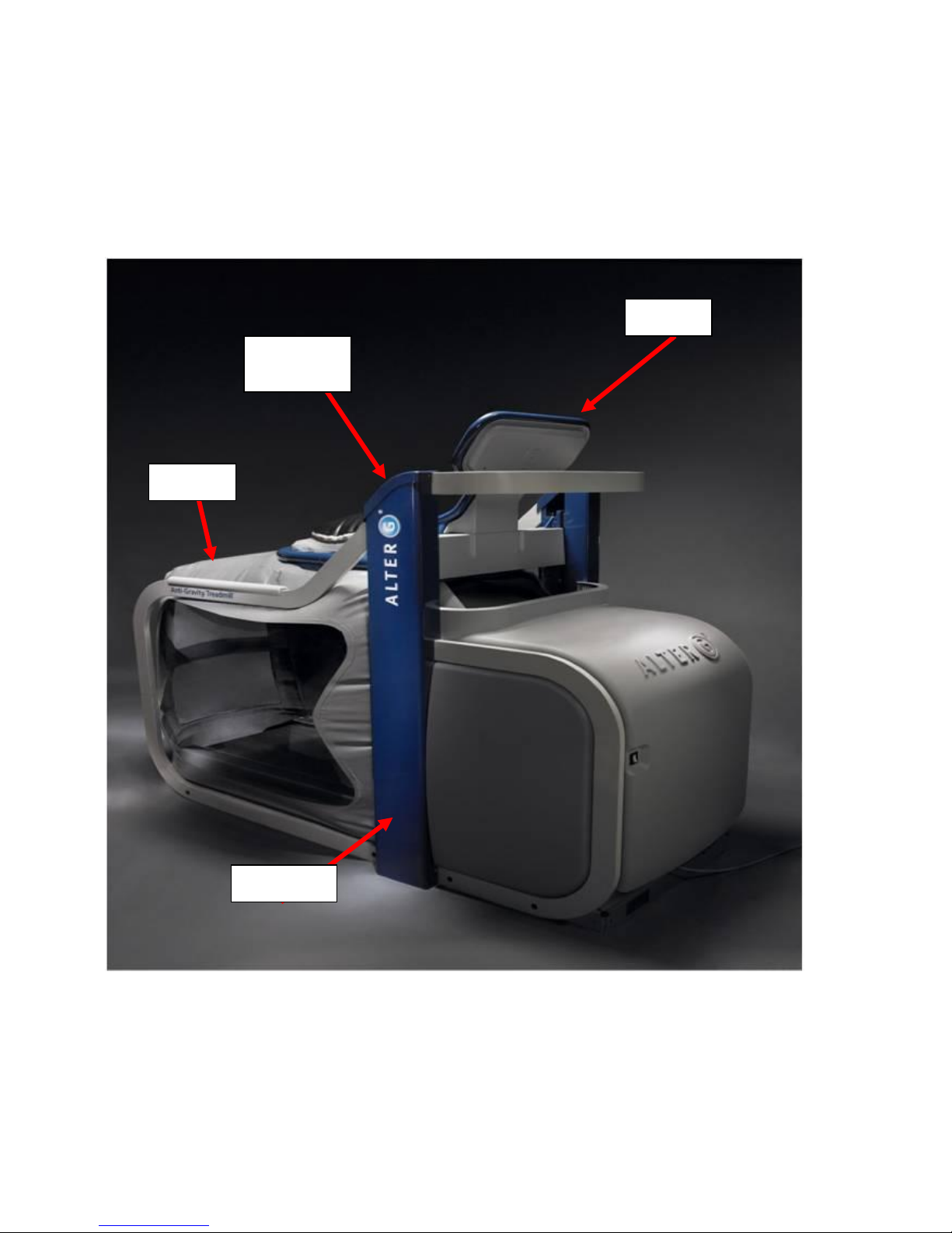
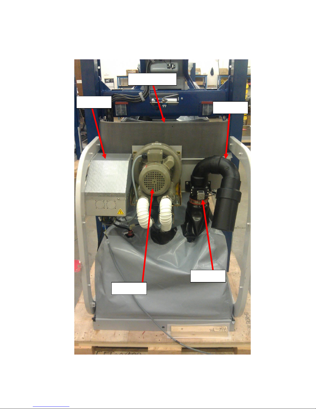
AlterG COMPONENT IDENTIFICATION ...................................................................................... 4
Exterior Components ............................................................................................................ 4
Interior Components............................................................................................................. 5
GENERAL INSTALLATION GUIDELINES ....................................................................................... 6
Safety..................................................................................................................................... 6
Tools ...................................................................................................................................... 6
Fasteners and Torque Specifications..................................................................................... 7
SITE REQUIREMENTS................................................................................................................. 8
Treadmill Dimensions............................................................................................................ 8
Electrical Requirements ........................................................................................................ 8
INSTALLATION OF THE FULLY ASSEMBLED ALTERG (roll-in)...................................................... 9
Moving the AlterG System to a Location .............................................................................. 9
Removing the AlterG from the Pallet.................................................................................... 9
Removing the AlterG from the Dollies.................................................................................. 9
Preparing the System for Operation ................................................................................... 10
ASSEMBLY INSTRUCTIONS FOR THE DISASSEMBLED UNIT ..................................................... 12
Moving the AlterG............................................................................................................... 12
Unpacking............................................................................................................................ 12
Base Assembly..................................................................................................................... 15
Installing the Stanchion Assembly ...................................................................................... 16
Installation of the Cockpit ................................................................................................... 18
Installation of the Cable Guide ........................................................................................... 20
Diagnostic Mode ................................................................................................................. 22
Check Drive Belt Tension..................................................................................................... 22
Check Treadbelt Tracking .................................................................................................... 23
Check Treadbelt Tension ..................................................................................................... 23
Bag Installation.................................................................................................................... 24
Rail Installation.................................................................................................................... 29
Install the Main Power Cable .............................................................................................. 31
Final Installation Steps ........................................................................................................ 32

4
AlterG Installation Manual 105440 rev C
ALTERG COMPONENT IDENTIFICATION
These photos identify the major components and nomenclature used in the assembly of the
AlterG system.
Exterior Components
Front cover
Side cover
Cockpit
Bag
Stanchion
Caps
Stanchion

5
AlterG Installation Manual 105440 rev C
Interior Components
PDU
Blower
Valve
Muffler
Modesty Panel

6
AlterG Installation Manual 105440 rev C
GENERAL INSTALLATION GUIDELINES
Safety
Many assemblies of the AlterG are heavy. Use good lifting technique and obtain assistance
when lifting and moving these components.
Use appropriate lifting and moving aids.
It is recommended that installers wear steel toed shoes while working around the AlterG.
Tools
The following tools are recommended for installing the AlterG.
Two 4-wheel dollies
Johnson bar (J-bar)
AlterG lifting pin
1/4” drive ratchet wrench
9/16”, 6 or 12 point, 1/4” drive socket
1/16”, 5/64”, 1/8”, 5/32”, 3/16”, 1/4”, 7/32” Allen wrenches. These are available in most
Allen wrench sets.
3/16”, 7/32”, 1/4” Allen sockets for 1/4” drive ratchet wrench
7/16”, 1/2” open end or combination box wrench
1/4”, 5/16” nut drivers
Adjustable wrench
Right angle, #2 Phillips screwdriver
#2 Regular (slotted) screwdriver
Small pair of diagonal cutters for cutting zip ties
Zip ties
Loctite 242 medium strength, LocTite 222 low strength
Digital volt meter
Wipes for cleaning
Caution: You may be injured or damage the product if you fail to
follow the procedures and safety tips outlined in this document

7
AlterG Installation Manual 105440 rev C
Fasteners and Torque Specifications
Type
Socket Flathead
Socket Flathead
Socket Cap Screw
Socket Cap Screw
Socket
Cap Screw
Size
3/8”-24 x 5/8”
Black oxide with
nylon locking patch
5/16”-24 x 1”
Black oxide with
nylon locking patch
3/8”-16 x 3/4”
black oxide with
nylon locking patch
5/16”-24 x 3/4”
Black oxide with
nylon locking patch
5/16”-18 x 3/4”
Black oxide with
nylon locking patch
Quantity
8
6
8
6
4
Application
Stanchion to Base
Stanchion to Rails
Rails to Base
Stanchion to Rails
Stanchion to Base
Assembly
Torque
20 ft-lb / 19 Nm
12 ft-lb / 16 Nm
20 ft-lb / 19 Nm
12 ft-lb / 16 Nm
12 ft-lb / 16 Nm
Type
Socket
Buttonhead
Socket
Flathead
Socket
Buttonhead
Socket
Flathead
Socket
Buttonhead
Socket
Buttonhead
Size
1/4”-20 x 3/8”
6–32 x 1/2”
6–32 x 3/8”
¼-20 x 3/4"
6-32 x 1/4"
8-32 x 1/2"
Quantity
4
6
2
2
14
8
Application
Top rail to
Bottom rail
Console rear
Stanchion caps
Cable guide to
PDU
Stanchion
covers
Bag to Cockpit
Assembly
Torque
6 ft-lb / 8 Nm
9 in-lb / 1 Nm
9 in-lb / 1 Nm
6 ft-lb / 8 Nm
9 in-lb / 1 Nm
32 in-lb / 1Nm

8
AlterG Installation Manual 105440 rev C
SITE REQUIREMENTS
Treadmill Dimensions
Height: 74” (188 cm)
Width: 38” (96.5 cm)
Length: 84” (213 cm)
Ceiling height minimum: 96” (244 cm)
Note: Place the right front corner of the system within 8 feet of the power outlet.
Electrical Requirements
A dedicated 20 Amp, 220V circuit; with a NEMA 6-20 receptacle required within eight feet of
the front right corner of the AlterG Anti-Gravity Treadmill®.
Single Phase NEMA 6-20R Receptable
Voltage across A and B: 200-240VAC

9
AlterG Installation Manual 105440 rev C
INSTALLATION OF THE FULLY ASSEMBLED ALTERG (ROLL-IN)
Moving the AlterG System to a Location
The Alter System comes strapped to a wooden pallet; because of the weight (≈ 700 lbs) and
size of the machine, the only practical way of moving the AlterG while on the pallet is with a
forklift. Alternatively, you can remove the AlterG from the pallet for moving as outlined
below.
CAUTION: NEVER MOVE THE SYSTEM WITH A FORK LIFT IF IT IS OFF THE PALLET. MOVING IT
IN THIS WAY CAN BEND THE LOWER FRAME.
Removing the AlterG from the Pallet
If it is impractical to forklift the unit to the install site, you must slide the system off of the
pallet onto two moving dollies. When moving the unit, you should only push or pull on the
vertical stanchions. The stanchions tie into the base frame and can withstand the loads.
Note: This is a multiple person task
The object is to slide the AlterG System off so that the front and rear frame members
rest on the middle of their respective dolly.
Position the first dolly in front (heaviest portion of the machine) and to the side and
slide the system onto the dolly. Place the second dolly in back and slide the system
onto it.
Once both dollies are in place, use ratchet straps to secure the system to both
dollies.
Safely maneuver system to final location.
Removing the AlterG from the Dollies
If the AlterG is going to be placed on a hard surface, you can slide the AlterG into position
once off the dollies. However, if it is being placed on something like indoor/outdoor carpet
the system must be removed from the dollies in its final resting position.
Caution: You may be injured or damage the product if you fail to
follow the procedures and safety tips outlined in this document

10
AlterG Installation Manual 105440 rev C
Preparing the System for Operation
1. When unit is in place, verify that the counterweight cables are in the pulley grooves
as in the image below (stanchion caps are shown removed for clarity).
2. On each inner stanchion wall there is a ½” bolt as pictured below. Use a ¾” box or
socket wrench to loosen and remove the bolt and washer. These bolts and washers
can be discarded upon removal.
Counterweight
bolt

11
AlterG Installation Manual 105440 rev C
3. Release the cockpit lock and cycle the cockpit up and down several times to confirm
the cables are tracking properly.
4. Check for cosmetic damage and touch-up if necessary.
5. Wipe down all exterior surfaces.
6. Get inside the bag and confirm wire routing to the treadmill is properly secured and
clears any moving parts of the treadmill.
7. Perform a visual check of treadmill location on the base. Confirm that the treadmill is
centrally placed side to side and that the side rails of the treadmill are parallel with
the side rails of the base.
8. Check wall voltage. The M310/ M320 will operate between 200 –240Vac.

12
AlterG Installation Manual 105440 rev C
ASSEMBLY INSTRUCTIONS FOR THE DISASSEMBLED UNIT
Moving the AlterG
1. Verify site inspection survey, final location,
and route to final location.
2. Use a pallet jack or transport on furniture
dollies. A J-bar is useful for lifting the pallet
for placement of the dollies.
Unpacking
1. Unscrew and remove the wooden shipping frame.
Note: Use care when removing the frame to avoid
scratching any of the underlying components.
2. Inspect unit for damage after unwrapping, before
moving. Take photos of any damage.
3. Leave protective wrapping on stanchion covers,
rails, etc as long as possible.
4. Remove the counterbalance weights and set aside.
Note: Each weight weighs 45 lbs (20kgs), so use
good lifting technique.

13
AlterG Installation Manual 105440 rev C
5. Move stanchion/rail/front panel
assembly off of pallet. Note: The
assembled unit weighs about 254 lbs
(115 kgs); have plenty of help on hand
to move safely.
6. Move cockpit into room. The cockpit weights about
95 lbs (43 kgs). It is recommended that two people
carry the unit. Note: Use good lifting technique
when moving the cockpit.
7. Remove the load cell cables from the interior of
the treadmill motor cover. Note: be very careful
when operating around these cables to avoid
damaging them.
Caution: You may be injured or damage the product if you fail to
follow the procedures and safety tips outlined in this document

14
AlterG Installation Manual 105440 rev C
8. Remove the treadmill off the
base and set it aside. Note: the
treadmill weighs 250 lbs (114
kgs), have plenty of help when
moving it.
9. Carry the base to its final
location. The power cord is 10
feet in length. Place the front
right corner of the base within 8
feet of the electrical outlet to
provide slack for cord routing.
Within 8 feet
of outlet
Load cell cables
exit here
Caution: You may be injured or damage the product if you fail to
follow the procedures and safety tips outlined in this document

15
AlterG Installation Manual 105440 rev C
Base Assembly
1. Clean any debris off of the surface of
the base.
2. Place the treadmill onto the base.
3. Ensure the treadmill rear supports
are installed properly in the rear
restraints of the base. The support
should be centered in the restraint
front to back and side to side. It
should not bind in the restraint.
4. Ensure the front elevation wheels of
the treadmill are properly oriented
between the front guides on the
base and that they are sitting
squarely on the load cells. Note:
The wheels should not ride up on
the top of the guides.
5. Remove the blue tape from each
corner of the base and pull out the
black plastic rods and place aside.

16
AlterG Installation Manual 105440 rev C
Installing the Stanchion Assembly
1. Remove one of the 2 x 6 boards from
the crating and place on top of a
furniture dolly to support the stanchion
assembly.
2. Remove the plastic front panel from the
stanchion assembly. You may also want
to remove the front rails and panels to
avoid scratches. Place the unit on the
dolly as shown. Wheel the unit to the
installation location.
Note: If the site does not allow use of a dolly
or similar moving aid, the assembly can be
moved by hand. When moving by hand, have
plenty of help and lift the unit only by the
stanchions. Lifting by any other component of
the assembly can result in damage to the unit.
3. Place the stanchion assembly over
the treadmill base. Note: Lower it
in from the top or bring it in from
the rear to avoid damaging the
load cell cables. Do not slide it in
from the front of the unit.
Caution: You may be injured or damage the product if you fail to
follow the procedures and safety tips outlined in this document

17
AlterG Installation Manual 105440 rev C
4. Fasten each stanchion to the base
frame using 4 of the 3/8 –24
flathead screws provided. Install
the screws so they are snug, but do
not tighten at this time.
5. The rear of the stanchion should be
bolted to the frame with two 5/16 -
18 socket cap screws. They are
inserted through the cutout in the
base of the stanchion. Do not
tighten at this time.
6. Bolt the front side rails to the base
using two 3/8 x 16 socket cap
screws on both sides. You may
have to look through the outer
clearance hole of the rail to line up
the inner rail hole with the
threaded hole in the base. Do not
tighten at this time.

18
AlterG Installation Manual 105440 rev C
Installation of the Cockpit
1. Prepare the cockpit for installation.
Unwrap and/or untangle the
counterweight cables.
2. Make sure the cockpit locking pins
are retracted by moving the cockpit
latch to the unlocked position before
attempting to place the cockpit in
the stanchions.
3. The cockpit weighs about 95 lbs (43 kg).
Use two people, one on either side of the
cockpit. Lift the cockpit and insert the
bearing carriages into the top of
stanchions, ensuring that aluminum pads
are aligned to fit into channels.
Note: The cable guide will be sticking out in
front of the cockpit - make sure it does not catch
on the modesty panel when the cockpit is
lowered.
4. Once cockpit is inside the stanchion channels, lock it into place.
Locking pins
Aluminum pads

19
AlterG Installation Manual 105440 rev C
5. Attach the counterweight cables to
the counterweight. Use Loctite 242
on the threads.
6. Seat the counterweight cable in the
pulley.
7. Lower the counterweight while maintaining
tension in the cable. Align the counterweight so
that the tapped hole faces inward.
8. Move the cockpit over its full range from top to
bottom checking to make sure it operates
smoothly.

20
AlterG Installation Manual 105440 rev C
Installation of the Cable Guide
1. Unpack the cable guide. A spring
steel piece shapes the guide as it
exits the cockpit carriage. Make sure
the spring steel is fully enclosed in
the guide.
2. Verify that all links are connected
and all cross bars are snapped shut.
3. Snap cable guide to the lower
bracket on the bottom of the power
box. Ensure that the cables are
routed straight out of the bracket.
4. Move load cell cables to outside of
machine and all other cables to
inside of machine
5. Connect the load cell cables exiting from the cable
guide to the corresponding cables coming from
the base. The load cell cables are labeled. Make
sure the connectors lock in place.
End link att ached
to power box
This manual suits for next models
2
Table of contents
Other AlterG Treadmill manuals

AlterG
AlterG VIA User manual

AlterG
AlterG M310 User manual

AlterG
AlterG Anti-Gravity Treadmill User manual

AlterG
AlterG Anti-Gravity Treadmill Via 400 User manual

AlterG
AlterG Anti-Gravity Treadmill User manual

AlterG
AlterG Anti-Gravity M320 Stride Smart User manual

AlterG
AlterG Anti-Gravity Treadmill Fit Series User manual

AlterG
AlterG Anti-Gravity Treadmill Via 400 User manual

AlterG
AlterG Pro 100 User manual

AlterG
AlterG Pro 500 Anti-Gravity Treadmill User manual