ALTHEN NM1-IP-2L-420-B05 User manual

Germany | Switzerland | Austria
Althen GmbH Mess- & Sensortechnik
Tel: + 49 (0)619 - 70060
Benelux
Althen bv Sensors & Controls
Tel: +31 (0)70 392 4421
France
Althen / DB Innovation
Tél : 0033 (0)4 67 78 61 66
Sweden
Althen Sensors & Control AB
Tel. +46 (0)8 7 9 24 90
USA | Canada
Altheris Inc Sensors & Controls Inc.
Tel: +1 8 8-633-3 72
Other Countries
please contact us
by email at
www.althen.de
V2.1
eng
Single Axis
Tilt Measuring System

2 | 12
Content
1 General Information ........................................................................................................................... 3
1.1 Safety Instructions ...................................................................................................................... 3
1.2 Qualified Personnel ................................................................................................................... 3
1.3 Intended Use ............................................................................................................................... 3
2 Instructions for use of the measuring amplifier ..................................................................... 4
3 Technical Description ........................................................................................................................
4 Terminal Assignment........................................................................................................................
4.1 Supply Voltage ............................................................................................................................
4.1.1 Load Impedance ......................................................................................................................
Starting up ........................................................................................................................................... 6
.0.1 Description of measuring axis ........................................................................................... 6
.1 Calibration of the tilt measuring system ........................................................................... 7
.1.1 Adjusting the zero-point ...................................................................................................... 7
.1.2 Adjustment / calibration of the amplifier ..................................................................... 7
6 Maintenance ........................................................................................................................................ 8
7 Old appliances disposal.................................................................................................................... 8
Appendix .............................................................................................................................................. 9
Datasheet ............................................................................................................................................ 9
Order Designation ............................................................................................................................ 9
Housing Dimensions ...................................................................................................................... 10
EMC-Mounting ................................................................................................................................. 11

3 | 12
General Information
To ensure reliable and safe operation, the measuring amplifier must be operated in compliance with
the specifications according to this technical description only. These regulations must also be observed
if accessories, which have been ordered from Althen Mess- & Sensortechnik GmbH together with the
measuring amplifier, are being used.
Notice: Every person who is in charge for the start-up or service of this measuring amplifier must have
read this technical manual and must have understood the safety instructions in particular.
. Safety Instructions
When using the amplifier, the legal- and safety regulations for each case of application must be
observed. To avoid risks for the system or the operator the following points are to be considered.
■
If any visual damage or malfunctions are noticed, the measuring system must be switched
off and marked appropriately.
■
Disconnect the supply voltage before opening the device.
■
The complete measuring unit must be protected against contact and influence of
unauthorised persons.
■
In the case of a safety-relevant application, where a potential malfunction could cause
damage to property or persons, it is imperative that an additional, independent monitor is
provided.
■
In combination with sensors, the maximum loads / pressures etc. must never be exceeded.
If you have reasons to assume that safe operation is no longer possible, immediately take the device
out of operation and secure it against unintentional operation.
.2 Qualified Personnel
This measuring system must be operated by qualified personnel and in compliance with the relevant
technical specifications only. Qualified personnel include such persons who are conversant with the
setting up, mounting and starting up of the measuring system and who have qualifications that are
appropriate for the tasks they're about to perform.
.3 Intended Use
Amplifiers from Althen Mess- & Sensortechnik GmbH serve to measure the intended measurand and
the evaluation thereof in combination with one or more sensors. Any other use over and above that is
regarded as non-intended use.

4 | 12
2 Instructions for use of the measuring amplifier
Notice: The parameterizations, further information concerning the scaling as well as the customized
analogue output can be found on the additional page "Device-Configuration".
Since this amplifier is a highly sensitive measurement technology product, it must be used for its
intended use as well as the described operating conditions only. Initial start-up and changes in setup
and settings must be done by qualified personnel only. To prevent interventions / modifications made
by unauthorized personnel, suitable measures must be taken. Both function and calibration must be
checked regularly.
The amplifier must be operated with a separate power source used for measurement devices only.
Shielded cables, preferably twisted in pairs should be used only. The EMC-installation instructions must
be complied with.
The amplifier is contained in an aluminum housing which is equipped with an EMC- cover gasket as
well as EMC-cable glands. After initial start-up the lid is to be closed properly. This ensures IP-level 6 .
The housing is to be mounted on a grounded object /surface.
The tilt measuring system must be connected to clean earth-potential. Please refer to the EMC-
Mounting-Instructions in order to connect the sensor-shields correctly. To avoid possible potential
equalization currents over the shield of the cable to the following evaluation unit, this shield should be
connected over a suitable capacitor (10 nF / 200 V).
Overall the shield connections must be done properly to EMC-standards (as short as possible with large
wire cross-section) and connected to a central point (star grounding). In order to not increase the
disturbance sensitivity of the amplifier, all cables should be kept as short as possible and should not be
extended. Possible cable-bound disturbances (i.e. noise) must be blocked very near the cable ends
(evaluation unit) by suitable measures.
If it is to be expected that the amplifier is, as example, cleaned with a high-pressure cleaner/ steam jet
an additional protection shall be provided.
Notice: Changes of the measuring system of any kind demand for the explicit approval of Althen Mess-
& Sensortechnik GmbH. Changes of any kind done without that approval exclude all possible warranty
and/or liability of Althen Mess- & Sensortechnik GmbH.
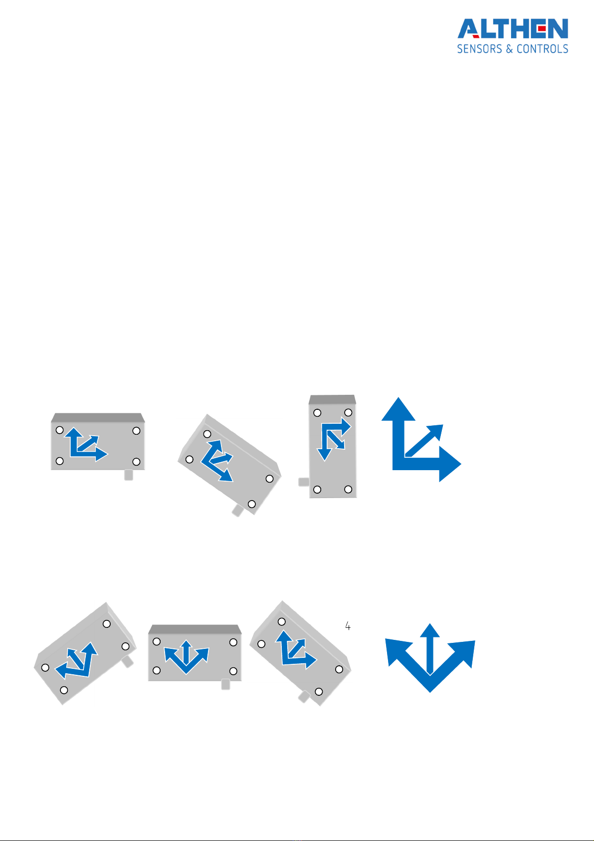
Please note that the tilt measuring system responds not to inclination changes only, but as well to
vibrations and to acceleration forces. If necessary and been ordered, a low pass filter can be installed.

| 12
3 Technical Description
This single axis, industrial tilt measuring system, which consists of one none-contact sensor and an
electronic customized for said sensor, serves to measure accurate tilt angles in x-axis and it is intended
for side wall mounting. Depending on the version the tilt angle can be between ± 3 up to ± 60°, or
between 0 … 10° to 0 … 90°.
A standard analogue output of 4 … 20 mA is available for further evaluation.
The measuring system is contained a robust aluminium die cast enclosure which is perfectly suited for
rough industrial environment. Additionally, the measuring system has been encapsulated to meet IP68
specifications and be better protected against vibrations.
4 Terminal Assignment
The electrical connection has been made via EMC cable glands and soldered inside. The shield of the
cable is connected to the housing.
Clamp Description Color
1 18 … 28 VDC red
2 Signal black
4. Supply Voltage
The supply voltage can be 18 … 28 VDC.
It is to be noted, that the voltage determines the max load impedance. For instance: a voltage of 24
VDC allows a max. load impedance of 00 Ohms.
4. . Load Impedance
The maximum load impedance depends on the supply voltage and is:
[18 VDC = 200 Ohm]
24 VDC = 00 Ohm
[28 VDC = 700 Ohm]

6 | 12
5 Starting up
Before mounting, all transport protection has to be removed and disposed of properly.
The measuring object is to be leveled horizontally (e.g. using the PRO3600 protractor from ALTHEN).
■
The sensor is to be mounted to a vertical surface at the object to measure.
■
After taking of the lid the mounting holes are visible.
■
The tilt measuring system is to be connected according to the terminal assignment. The
EMC-mounting instructions are to be complied with.
■
System is to be powered up.
■
Allow the measuring system approx. 1 minutes to warm up.
■
After levelling the system out 12 mA are to be adjusted.
■
If the range of adjustment should not be sufficient the mounting must be changed.
■
Both function and calibration are to be checked.
■
In order to ensure protection class IP68, the lid must be closed properly after initial start-up.
5.0. Description of measuring axis
Versions 0 … xx°
(Note: figure shows version 0…90°)
Versions 0 … ± xx°
(Note: figure shows version 0…± 4 °)
20 mA = xx°
12 mA = xx°/2
4 mA = 0°
12
mA
=0°
20 mA=+xx°
4 mA=-xx°

7 | 12
5. Calibration of the tilt measuring system
Notice: The measuring system is factory pre-calibrated. Under normal circumstances, an adjustment is
not necessary.
After mounting the system, caused by deviations of mounting, a slight correction of the zero-point is
often necessary. The calibration of the span / full-scale is to be checked.
5. . Adjusting the zero-point
■
- Connect an amperemeter
■
- The measuring object is to be leveled out.
■
- Adjust the zero point with the potentiometer „N“ to
12,00 mA (version ± xx°) or
4,00 mA (version 0 … xx°).
Notice: The zero-point adjustment range is approx. 10 %. If this might not be sufficient, the measuring
object is to be re-leveled.
5. .2 Adjustment / calibration of the amplifier
Before shipping, the measuring system has been pre-adjusted. Using the potentiometer “V” should not
be necessary.
Anyway, if a re-adjustment is necessary, it is done as follows:
■
Level the measuring system with the help of e.g. precision spirit level.
■
Now adjust the zero-point.
■
Now tilt the measuring system about 80 … 100% of its maximum range.
■
Now use the gain /end value potentiometer (“V”) to set the analogue output to the desired
value.
For scaling of the analogue output applies:
Analogue output = 12 mA + Defined angle x 8 mA
Full range

8 | 12
6 Maintenance
The flawless function and calibration of the whole measuring system is to be checked regularly. This
inspection is also necessary after every repair or change of any component of the measurement
system.
7 Old appliances disposal
According to european and german law, it is prohibited to dispose of old electronic
devices into household waste, but must be collected and disposed of separately.
Amplifiers and measurement units manufactured and sold by Althen Mess- & Sensortechnik GmbH
serve B2B purposes only. Therefore, those old appliances must not be given to the communal disposer,
but must be given back to the seller or disposed of properly. If you need any further information, please
contact your local authorities.
These measures serve to protect the environment and allow recycling and recovery of valuable
materials. Furthermore, do electronic devices contain substances that may cause damage to the
environment if burned or dumped with normal household waste.

9 | 12
Appendix
Datasheet
Number of measuring axis: 1
Supply voltage: 18…28 VDC Protected against voltage reversal
Power consumption: ca. 3 W
Analogue output 4 … 20 mA (2-wire) Max. impedance depending on voltage
Frequency (-3dB): 0, Hz
Preferred measuring ranges ±3°, ± °, ±10°, ±1 , ± 20, ±30, ±4 °
0…10°, 0…30°, 0…4 °, 0…60°, 0…90° Other ranges on request
Accuracy at 23°C:
to ±10° tilt
±10° bis ± 30°
to 60°
±0,1 °
±0,2°
±0,2 °
Electrical connections:
3 m cable 2x0,2 mm² (AWG20), other lengths on request
Enclosure: EMC-aluminum die-cast
Protection class: IP68
Dimensions (W x H x D): 98x38x63 mm (w/o cable gland)
Weight: ca. 0g (incl. 3m cable)
Storage temperature range: -3 °C…+7 °C
Operating temperature range: -20°C…+60°C
Order Designation
NM1-IP-2L-24-420-… 1-axis measuring system
…-Bxx-… Bidirectional, xx=inclination measuring range, e.g. B4 = ±4 °
…-Lxx-… Left-handed, xx= inclination measuring range, e.g. L30 = 0 ... -30°
...-Rxx-... Right-handed, xx= inclination measuring range, e.g. R30 = 0 ... 30°
...-y m Cable length (1-120m) customer request

10 | 12
Housing Dimensions

11 | 12
EMC-Mounting
Enclosure with high-
frequency-seal
Keep enclosure closed
To improve the noise-
immunity feed the leads
through ferrite-rings
EMI-/RFI-approved
cable lead-through
connect to screen Use with cable
screen
Connect screen to
ground with a
ground
-
clamp
Amplifier/Sensor
Grounding case:
Case need to be
mounted on a
grounded surface!
1
st
Step
2
nd
Step
3
rd
Step
+ Skin cable
+ Lay open the braid
+ Lead cable through cap nut
+ Establish cable in clamping
+ put braid over clamping
+ Braid have to overlap the o-ring
approx. 2mm
+ Put clamping application in
Cable gland
+ Tighten cap nut
+ FINISHED!

12 | 12
Subject to modifications.
All information describe our products in general form.
Table of contents
Other ALTHEN Measuring Instrument manuals
Popular Measuring Instrument manuals by other brands

BURG WATCHER
BURG WATCHER ProfiScale CROSS operating instructions

Konica Minolta
Konica Minolta MYIRO-1 instruction manual

Anton Paar
Anton Paar PA 5 Product information

Sensitech
Sensitech TempTale Ultra Instructions for use

Katronic
Katronic KATflow 150 Quick start manual

Kaiterra
Kaiterra Sensedge Mini installation guide