ALTHEN NM1-2L-420-ATEX User manual

Germany | Switzerland | Austria
Althen GmbH Mess- & Sensortechnik
Tel: + 49 (0)619 - 70060
Benelux
Althen bv Sensors & Controls
Tel: +31 (0)70 392 4421
France
Althen / DB Innovation
Tél : 0033 (0)4 67 78 61 66
Sweden
Althen Sensors & Control AB
Tel. +46 (0)8 7 9 24 90
USA | Canada
Altheris Inc Sensors & Controls Inc.
Tel: +1 8 8-633-3 72
Other Countries
please contact us
by email at
www.althen.de
V2.1
eng
Single Axis Inclination Measuring System
M1-2L-420-ATEX

2 | 16
Content
ATEX-Inspection Certificate 3
1 General Information 4
1.1 Safety Instructions
1.2 Qualified Personnel
1.3 Intended Use
1.3.1 ATEX-Accreditation / EU-Type Examination Certificate 6
2 Instructions for use of the measuring amplifier 6
3 Technical Description 7
4 Terminal Assignment 8
4.1 Supply Voltage 10
Mounting 11
.1 Starting Up 11
6 Maintenance 12
7 Old appliances disposal 12
Appendix 13
Datasheet 13
Order Designation 13
Housing Dimensions 14
Declaration Of Conformity 1

3 | 16
ATEX-Inspection Certificate

4 | 16

| 16
1 General Information
To ensure reliable and safe operation, the measuring amplifier must be operated in compliance with the
specifications according to this technical description only. These regulations must also be observed if
accessories, which have been ordered from Althen Mess- & Sensortechnik GmbH together with the
measuring amplifier, are being used.
otice: Every person who is in charge for the start-up or service of this measuring amplifier must have
read this technical manual and must have understood the safety instructions in particular.
1.1 Safety Instructions
When using the amplifier, the legal- and safety regulations for each case of application must be observed.
To avoid risks for the system or the operator the following points are to be considered.
■
If any visual damage or malfunctions are noticed, the measuring system must be switched off
and marked appropriately.
■
Disconnect the supply voltage before opening the device.
■
The complete measuring unit must be protected against contact and influence of unauthorised
persons.
■
In the case of a safety-relevant application, where a potential malfunction could cause damage
to property or persons, it is imperative that an additional, independent monitor is provided.
■
In combination with sensors, the maximum loads / pressures etc. must never be exceeded.
If you have reasons to assume that safe operation is no longer possible, immediately take the device out
of operation and secure it against unintentional operation.
1.2 Qualified Personnel
This measuring system must be operated by qualified personnel and in compliance with the relevant
technical specifications only. Qualified personnel include such persons who are conversant with the
setting up, mounting and starting up of the measuring system and who have qualifications that are
appropriate for the tasks they're about to perform.
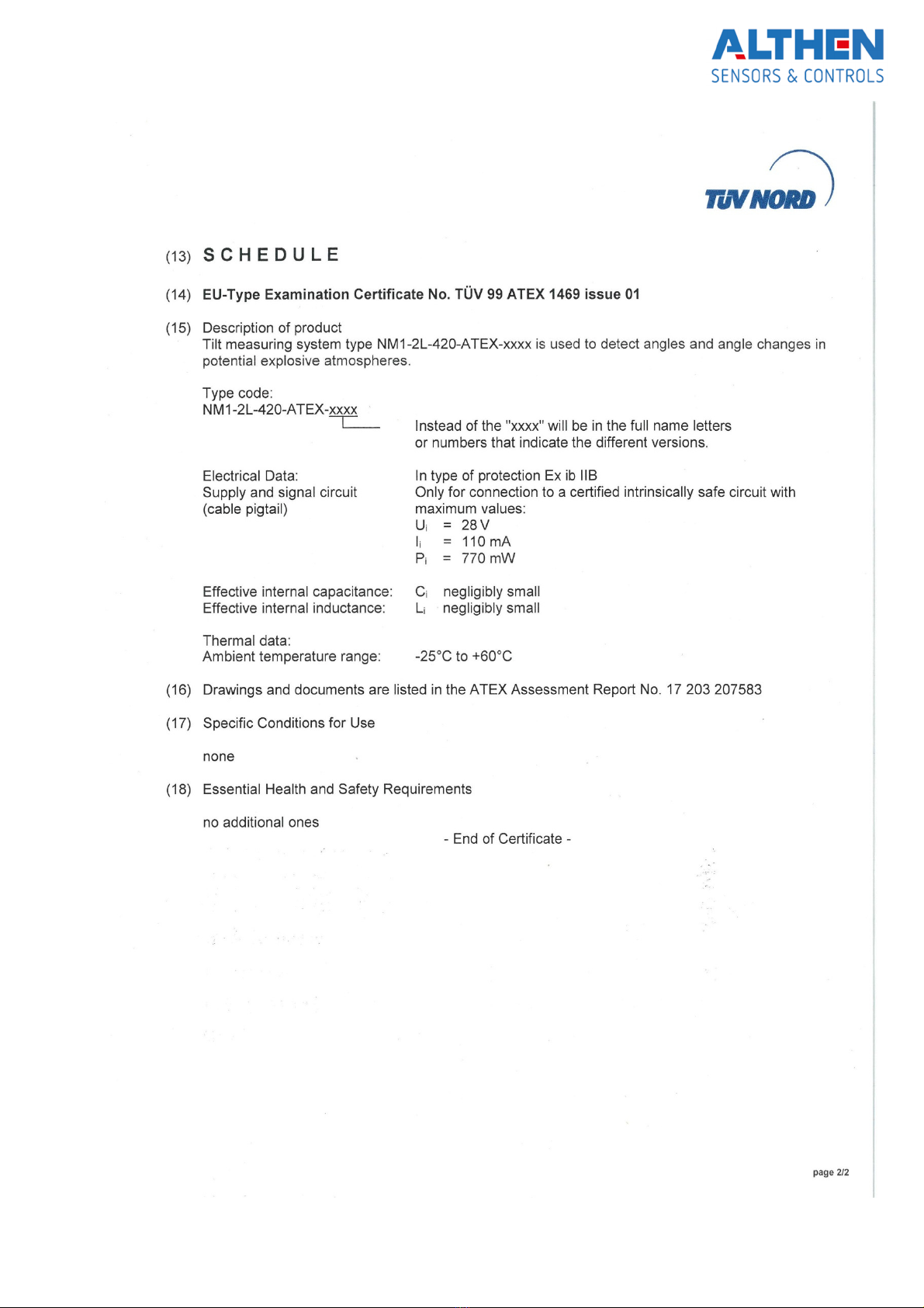
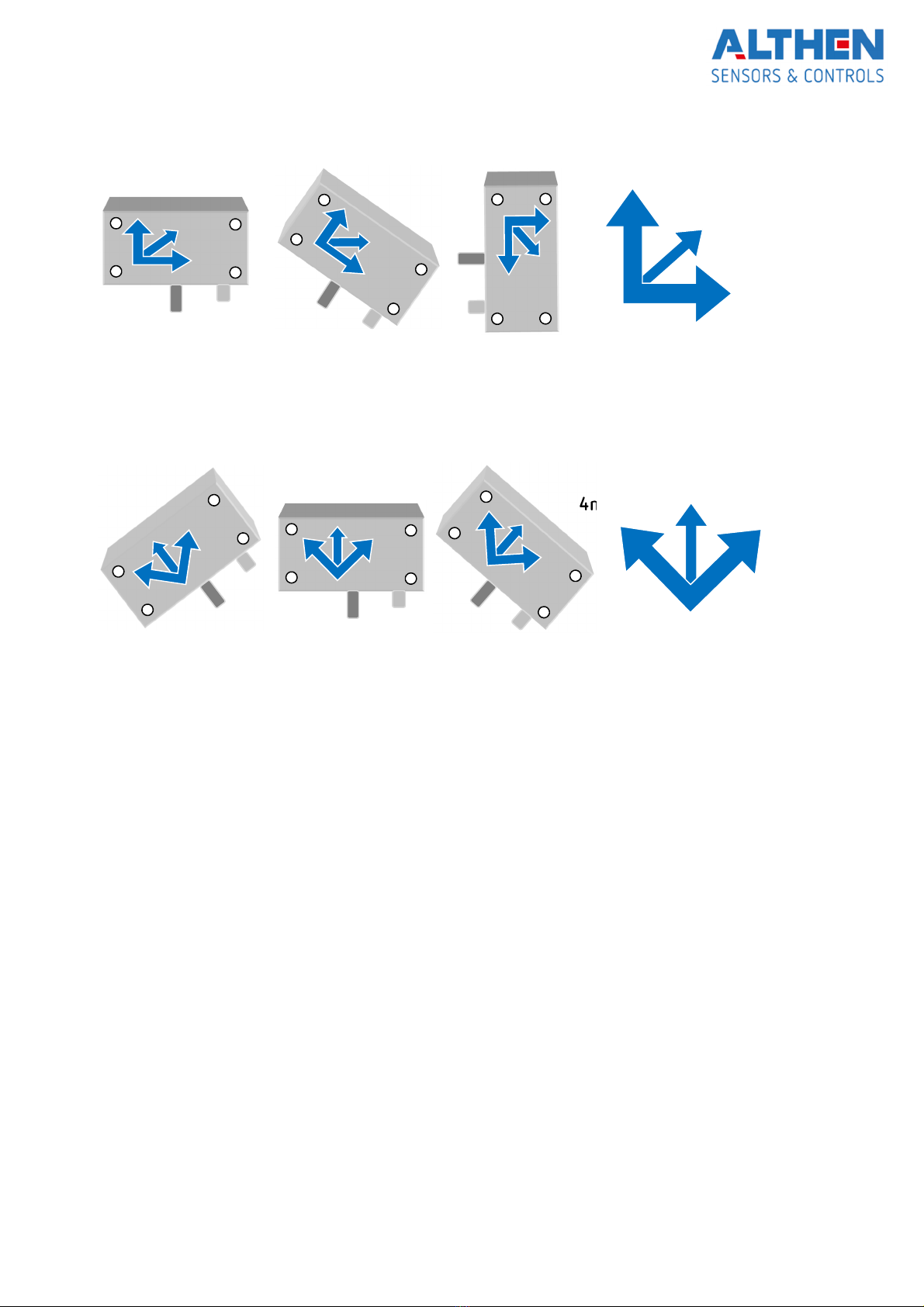
1.3 Intended Use
The described amplifier from Althen Mess- & Sensortechnik GmbH serve to measure, monitor and
evaluate inclination and it is fitted for explosion hazardous environments, according to
ATEX-standard 2014/34/EU. Any other use over and above that is regarded as non-intended use.

6 | 16
1.3.1 ATEX-Accreditation / EU-Type Examination Certificate
There’s an EU-type examination certificate for the described amplifier for operating it in accordance with
these regulations.
EU-type examination certificate name: TÜV 99 ATEX 1469
Under section „ATEX Inspection Certificate” is a copy of the EU-type examination certificate. The specified
data are by all means to be followed.
The electrical connections must be made inside a certified intrinsically safe circuit, with in the certificate
stated limits only.
2 Instructions for use of the measuring amplifier
otice: The parameterizations, further information concerning the scaling as well as the customized
analogue output can be found on the additional page "Device-Configuration".
Since this amplifier is a highly sensitive measurement technology product, it must be used for its intended
use as well as the described operating conditions only. Initial start-up and changes in setup and settings
must be done by qualified personnel only. To prevent interventions / modifications made by
unauthorized personnel, suitable measures must be taken. Both function and calibration must be checked
regularly.
The amplifier is contained in an aluminum housing which is equipped with an EMC- cover gasket as well
as EMC-cable glands. This ensures IP-level 68 (1m, 1h) according to DIN EN 60 29 (VE 0470).
otice: The case / amplifier must not be opened! Otherwise the gasket will be damaged and the
specified protection class / tightness will be reduced. If opened nonetheless, the gasket must be renewed
professionally.
The whole construction must be potential-equalized. Under no circumstances are there any potential
equalization currents over the cable shield allowed.
The housing is to be mounted on a grounded object /surface.
The tilt/ inclination measuring system must be connected to clean earth-potential. To avoid possible
potential equalization currents over the shield of the cable to the following evaluation unit, this shield
should be connected over a suitable capacitor (10 nF / 200 V).
Overall the shield connections must be done properly to EMC-standards (as short as possible with large
wire cross-section) and connected to a central point (star grounding). In order to not increase the
disturbance sensitivity of the amplifier, all cables should be kept as short as possible and should not be

7 | 16
extended. Possible cable-bound disturbances (i.e. noise) must be blocked very near the cable ends
(evaluation unit) by suitable measures.
otice: Changes of the measuring system of any kind demand for the explicit approval of Althen Mess-
& Sensortechnik GmbH. Changes of any kind done without that approval exclude all possible warranty
and/or liability of Althen Mess- & Sensortechnik GmbH.
Please note that the tilt measuring system responds not to inclination changes only, but as well to
vibrations and to acceleration forces.
3 Technical Description
For specifications, version and calibration of the measuring system, please refer to the additional page
“Device Configuration”. Potential options as well as special versions custom made are noted there.
This single axis, industrial tilt / inclination measuring system, which consists of one none-contact sensor
and an electronic customized for said sensor, serves to measure accurate tilt angles in x-axis and it is
intended for side wall mounting. Depending on the version the tilt angle can be between ± 3 up to ± 60°,
or between 0 … 10° to 0 … 90°.
Electrical connections are in 2-wire-technology.
The described amplifier from Althen Mess- & Sensortechnik GmbH serve to measure, monitor and
evaluate inclination related to the horizontal. The montage of the system is to be done with the cable
pointing down and not directly on a wall, but via an adapter, which allows a fine adjustment of the
mounting position. Although it’s been mentioned here in this manual, that it is not allowed to open the
lid of the system: the inside potentiometers must not be touched, i.e. the calibration must not be changed.
With a supply voltage of 24 VDC a current / signal of 4 … 20 mA is generated. This changing current can
be read out over a shunt resistor, which can than be processed from the following evaluation unit.
When exceeding the measuring range, the current may go up over 20 mA, depending on the supply
voltage and the shunt resistor.

8 | 16
otice: Supply and signal current: In ignition protection type intrinsically safe Ex ib IIB to connect in a
certified safe circuit with the following limits:
Ui = 28 VDC Ci = negligible
Ii = 110 mA Li = negligible
Pi = 770 mW
Thermal:
Environmental temperature range: -2 °C … +60°C
II 2 G Ex ib IIB T4 Gb
4 Terminal Assignment
The electrical connections of the inclination measuring system are made via a cable (e.g. Unitronic-FD CP
plus, 1x2x0,2 mm², outer sheath: polyurethane mix), which, depending on version of the system may vary
in length. The maximum of the length is 120 m. The cable shield is connected to the systems case. The
cable has to be laid effectively protected against damages.
Cable Unitronic-FD CP plus, 1x2x0,2 mm²
Clamp Description Color
1 +24VDC white
2 Signal brown

9 | 16
Version 0 … Rxx°
(example shows 0…90°)
Version 0 … Bxx°
(example shows ±4 °)
20 mA = xx°
12 mA = xx°/2
4 mA = 0°
20mA=+xx
4mA=-xx°
12mA=0°

10 | 16
4.1 Supply Voltage
The supply voltage can be 18 … 28 VDC. But it is to be taken into consideration, that the supply voltage
dictates the maximum load resistance.
With a supply voltage of:
…24 VDC the load resistance can be max. 00 Ohms.
…18 VDC the load resistance can be max. 200 Ohms.
otice: A Zener barrier reduces the max. possible load resistance. The resistance of the barrier is to be
taken into consideration when calculating the overall load resistance.
otice: Supply and signal current: In ignition protection type intrinsically safe Ex ib IIB
to connect in a certified safe circuit with the following limits:
Ui = 28 VDC Ci = negligible
effective inner capacity
Ii = 110 mA Li = negligible
effective inner inductivity
Pi = 770 mW

11 | 16
5 Mounting
The inclination measuring system is to be mounted according to standard EN6079-14. The system has to
be mounted, so that all labels are readable and all connections are within reach. The cable has to be laid
effectively protected against damages. By false application and operation of the system there’s danger of
explosion on site or surrounding area. In order to avoid that, it’s to be made sure that:
■
no equalization currents must flow over the system.
■
maintenance instructions are followed.
■
the system is not installed near operating equipment or material, which operating
temperature exceeds the allowed environment temperature of the system.
■
The cable length doesn’t exceed 120 m.
For further information please refer to chapter 3 “technical description”.
5.1 Starting Up
After a correct mounting as well as correct electrical connecting, a slight adjustment of the zero-point
may be necessary. For that, the measurement object must be leveled exactly horizontally and the
measuring system must be adjusted to either 4 mA, or 12 mA, depending on the version.
The measuring signal can be between circa 3,8 and 22 mA (whereas the upper value is depending on
the supply voltage).
After adjusting the zero point, the functionality and calibration of the whole system is to be checked.
Version Zero-point Multimeter range
-xx° … 0° … +xx° 12 mA Range 20 mA DC
0 … (+xx/2)° … +xx° 4 mA Range 20 mA DC
otice: The case / amplifier must not be opened! Otherwise the gasket will be damaged and the
specified protection class / tightness will be reduced. If opened nonetheless, the gasket must be renewed
professionally.

12 | 16
6 Maintenance
The flawless function and calibration of the whole measuring system is to be checked regularly. This
inspection is also necessary after every repair or change of any component of the measurement system.
7 Old appliances disposal
According to European and German law, it is prohibited to dispose of old electronic
devices into household waste, but must be collected and disposed of separately.
Amplifiers and measurement units manufactured and sold by Althen Mess- & Sensortechnik GmbH serve
B2B purposes only. Therefore, those old appliances must not be given to the communal disposer, but
must be given back to the seller or disposed of properly. If you need any further information, please
contact your local authorities.
These measures serve to protect the environment and allow recycling and recovery of valuable materials.
Furthermore, do electronic devices contain substances that may cause damage to the environment if
burned or dumped with normal household waste.

13 | 16
Appendix
Datasheet
Number of measuring axis: 1
Supply voltage: 18 … 28 VDC, Protected against voltage reversal
Power consumption: < 1 W
Analogue output / Capacity: 4 ... 20 mA (2-wire), Max. impedance depending on voltage
Frequency (-3dB): 0, Hz
Preferred masuring ranges
±3°, ± °, ±10°, ±1 °, ± 20°, ±30°, ±4 °, ±60°
0 … 10°, 0 … 30°, 0 … 4 °, 0 … 60°, 0 … 90°
Other ranges on request
Accuracy at 23°C:
Bis ±10°: ±0,1°
Bis ±30°: ±0,2°
Bis ±60°: ±0,2 °
Electrical connections:
Cable: FD CP plus 2 x 0,2 mm², Outer sheath: polyurethane-mix
Length as requested by customer
Cross-sensitivity < 1, % with 30° cross slope
Temperature drift of sensitivity < -0,2 %/K
Temperature drift of zero-point < ± 0,1 mV/K
Enclosure EMC-aluminum die-cast
Protection class: IP68 DIN EN 60 29 (VDE 0470), checking conditions: 1 h, 1 m water depth
An additional protection against jet-water is advised.
Dimensions (W x H x D): 11 x 64 x 3 mm (not counting the cable glands and grounding screw)
Weight: Ca. 800g incl. 10m cable
Storage temperature range: -2 ... +60 °C
Operating temperature range: -2 ... +60 °C
otice:
During operation of the system in an explosion hazardous environment the
data of the „EU-Baumusterprüfbescheinigung“ are to be followed.
Order Designation
NM1-2L-420-ATEX…
1-axis inclination measuring system suitable for explosion hazardous environment with ATEX-inspection certificate
…-Bxx-… Bidirectional, xx=inclination measuring range, e.g. B4 = ±4 °
…-Lxx-… Left-handed, xx= inclination measuring range, e.g. L30 = 0 ... -30°
...-Rxx-... Right-handed, xx= inclination measuring range, e.g. R30 = 0 ... 30°
...-y m Cable length (1-120m) customer request

14 | 16
Housing Dimensions
Unterteil
base
lid

1 | 16
Declaration Of Conformity

16 | 16
Subject to modifications.
All information describe our products in general form.
Table of contents
Other ALTHEN Measuring Instrument manuals