CP452
CP452CP452
CP452-
--
-009
009 009
009 MultiTouch
MultiTouchMultiTouch
MultiTouch™
™™
™
In
InIn
In-
--
-Wall Widescreen Panel
Wall Widescreen PanelWall Widescreen Panel
Wall Widescreen Panel
User’s Guide
400-0546-001
1
2) Align mounting wings
Frame
vertically to insert.
1) Set gap between frame
and wings to larger
than wall thickness.
PIN
SCREW
WING
Welcome!
We greatly a reciate your urchase of the CP452-009. We are sure you will
find it reliable and sim le to use. Su erior erformance for the right rice,
backed by solid technical and customer su ort is what ALTINEX has to offer.
We are committed to roviding our customers with
Signal Management Solutions
®
to the most demanding audiovisual
installations at com etitive ricing and we welcome you to join the ranks of
our many satisfied customers throughout the world.
1. Precautions and Safety Warnings
Please read this manual carefully and heed all warnings. Kee this manual
handy for future reference. These safety instructions are to ensure the long
life of your CP452-009 and to revent fire and shock hazards.
1.1 General
•There are no user serviceable arts inside. Qualified ALTINEX service
ersonnel must erform all service on the CP452-009.
1.2 Installation Precautions
•Place the CP452-009 in a dry area away from dust and moisture.
•To revent fire or shock, do not ex ose to water or moisture. Do not lace
in direct sunlight, near heaters, or heat-radiating a liances, or near any
liquid. Direct sunlight, smoke, or steam can harm internal com onents.
•Handle the CP452-009 carefully. Dro ing or jarring can cause damage.
•Do not ull any cables that are attached to the CP452-009.
•If not used for an extended eriod, disconnect from AC ower.
1.3 Cleaning
•Un lug the CP452-009 ada ter before cleaning and clean only with a dry
cloth. Never use strong detergents or solvents such as alcohol or thinner.
Do not use a wet cloth or water to clean the unit. Do not o en the unit to
clean.
1.4 FCC Notice
•This device com lies with Part 15 of the FCC Rules. O eration is subject to
the following two conditions: (1) This device may not cause harmful
interference, and (2) this device must acce t any interference received,
including interference that may cause undesired o eration.
•This equi ment has been tested and found to com ly with the limits for a
Class A digital device, ursuant to Part 15 of the FCC Rules. These limits
are designed to rovide reasonable rotection against harmful interference
when the equi ment is o erated in a commercial environment. This
equi ment generates, uses, and can radiate radio frequency energy and, if
not installed and used in accordance with the instructions found herein,
may cause harmful interference to radio communications. O eration of this
equi ment in a residential area is likely to cause harmful interference in
which case the user will be required to correct the interference at his own
ex ense.
•Any changes or modifications to the unit not ex ressly a roved by
ALTINEX, Inc. could void the user’s authority to o erate the equi ment.
2. Installation Procedures Pre aration
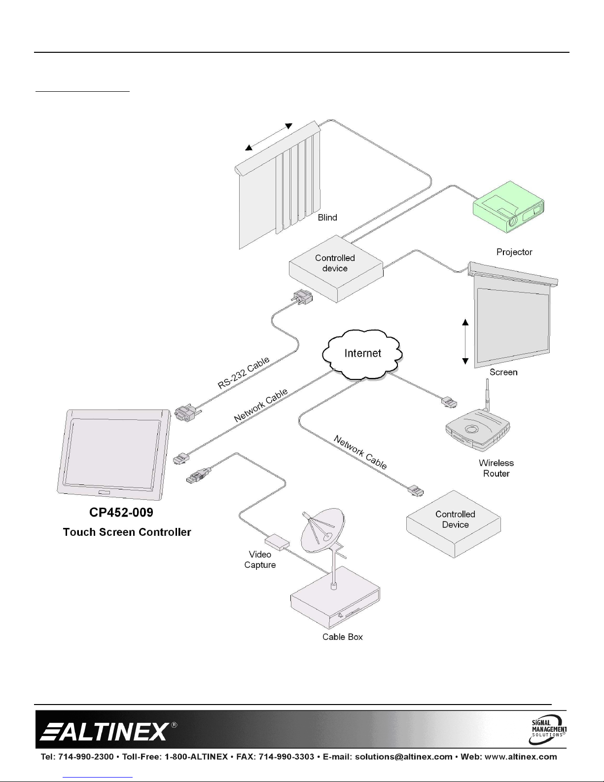
Ste 1. Make a list of the cabling requirements for the end-user a lication. What cable ty es are needed? For
exam le: CAT-5 for network connection, RS-232 for device control, ower, VIDEO, USB, etc.
Ste 2. Determine the best location for the touch anel then re are the cables based on ty e and length.
Installation - Hardware
Ste 3. Use the cutout tem late rovided with the anel to make the o ening in the wall. Test fit the anel into
the wall o ening. Make sure the mounting wings are aligned vertically and the ga between the frame
and the wing is a little more than the wall thickness before fitting the anel into the wall.
Ste 4. Remove the anel and set it aside. Route all cables needed for the installation through the wall o ening,
into the wall, and to the ro er source/destination. For ower, only use the ower ada ter rovided.
Ste 5. Once the cables are routed, connect the ower cable to the anel and verify the anel turns on
automatically. After the anel boots, disconnect the ada ter from AC ower.
Ste 6. Connect the remaining cables to the anel and insert the anel into the wall. Be careful not to bend the
cable connectors that are attached to the anel.
Ste 7. Make sure the wings are inside and behind the wall material. The anel fastens directly to the wallboard using
the attached, ca tive hardware. Tighten the mounting screws until each wing firmly "grabs" the wall.
Ste 8. Align the cli s on the inside of the bezel with the mounting ins inside the frame and ress firmly into lace.
U load A lication - Software
Ste 9. Connect the ower ada ter to AC ower and wait for the anel to "boot" u ; the anel boots automatically and launches
the AVSna
®
initial setu a lication dis laying system details. Follow the instructions to u load the a lication or quit the
setu a lication and use a USB drive to install the a lication.
Ste 10. Once all software has been installed, close all o en a lications and ut a shortcut to the a lication in the startu folder. Run the COMMIT
batch file located on the deskto and restart the com uter from the "Start" menu.
Ste 11. Verify the anel boots u and automatically launches the control software. The unit is now o erational.
3. Limited Warranty/Return Policies
Please see the ALTINEX website at www.altinex.com for details on warranty and return olicies.