ACNODES.COM
PANEL PC 1150 INSTALLATION GUIDE
!PANELPC1150systemunitx1
!Mountingbracketx6
!Screwkit
!PS/2keyboardadaptercablex1
I. CHECK-LIST
!PANELPCUser’sManual,SystemBoardUser’sManual,Quick
InstallationGuidex1Driver&UtilitiesCD-ROMx1(Product
InformationCD-ROM)
!Minijumper2Px10
Donotattempttoapplypowertothesystemifthereisdamagetoanyofitscomponents.
II. INSTALLATION
CPU, HDD, and DRAM Installation
ThestandardPANELPC1150 system already builds in a Pentium-level CPU,anda3.5”(oroptional2.5”) hard disk
drive.SBC8354-based systems feature two 72-pin SIMMsockets supporting system memory up to128MB. SBC8360,
ontheonehand,provides one 168-pin DIMM socket that supports system memory up to256MB(buffered)/128MB
(unbuffered).
1. Remove the 3 screws securing the riser card assembly’s back cover. Take off the cover by sliding it outward and pulling it upwards as pointed by the
arrows. If your system does not come with a riser card assembly, proceed to step 2.
2. Another 6 screws, located on the upper perimeter (3) and lower half (3), needs to be removed. These screws are the screws bolting the system’s rear
cover to the main unit.
3. Take off the system’s rear cover (and the riser card assembly).
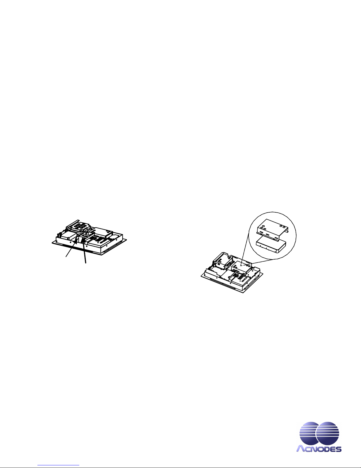
4. See the illustration for the exact locations of your HDD, CPU and DRAM sockets.
After making the necessary upgrades or modifications to your HDD, CPU, and DRAM, restore the system back to its original form by following instructions 4 to
CPU
DRAM
HDD
Bracket
CD-ROM and FDD Installation
1. Remove the 3 screws securing the riser card assembly’s back cover. Take off the cover by sliding it outward and pulling it
upwards as pointed by the arrows. If your system does not come with a riser card assembly, proceed to step 2.
2. Another 6 screws, located on the upper perimeter (3) and lower half (3), needs to be removed. These screws are the screws
bolting the system’s rear cover to the main unit.
3. You may now take off the system’s rear cover (along with the riser card assembly).
4. See the illustration for the exact locations of your CD-ROM and FDD slots. There are 2 screws mounted on the cover of each
slot. Remove these screws. Store the covers at a safe place for future use.
5. Mount the FDD and CD-ROM drives as shown on the illustration. Make sure to secure the drives using all 8 screws located on
both sides of the expansion bay.
6. After completing the installation, restore the system back to its original form by following instructions 3 to 1.


