Alto Topax Hygiene System S 5000 Manual

UK - Vers. 1.0 - 17.01.97
Directions for Use
Topax Hygiene System
Automatic Satellite S 5000
and
Automatic Main Station S 6000

Vers. 1.0 - 17.01.97

Vers. 1.0 - 17.01.97
Contents Page
1. Preface 1
1.0 Application 1
1.1 Special Warnings 1
1.2 Safety Instructions 2
2. Product Survey 3
2.0 Guidelines for Pipe Connections 3
2.1 Basic Unit S 5000 5
2.2 Accessories 5
2.3 Basic Unit S 6000 6
2.4 Accessories 6
3. Description of Function 7
3.0 Flow Charts 7
3.1 Electric Diagrams 9
3.2 Function of User Pack System (accessory) 13
4. Installation 14
4.0 Directions for Mounting 14
4.1 Water Connection 17
4.2 Connecting S 6000 with S 5000 18
4.3 Air Connection 18
4.4 Electric Connection 19
4.5 Supply of P3 Topax Products 19
5. Operation Instructions 21
5.0 Symbols 21
5.1 Layout Drawings 22
5.2 Start up Procedures 24
5.3 Directions during Operation 24
5.4 Stop Procedures 25
5.5 System Safety 26
6. Technical Specifications 27
6.0 Technical Data 27
6.1 Identification Plate 28
7. Maintenance 29
7.0 Instructions 29
7.1 Trouble Shooting and Remedy 30
7.2 Recommended Spare Parts 33
8. Components 34
8.0 Exploded Drawings of Stations with Spare Parts List 34
8.1 Drawing of P3 User Pack with Spare Parts List 43
9. Warranty 44
10. User Service 45
10.0 International Henkel-Ecolab Address List 45

Vers. 1.0 - 17.01.97

Vers. 1.0 - 17.01.97 1
1. Preface
Topax Hygiene Systems are used for rinsing, foaming or spraying of detergents and
sanitisers. The formation of foam is performed by mixing water, detergent or sanitiser
and compressed air in a specially designed injector system.
It is important that your operational staff reads these directions for use prior to
installation and start of operation. Operation as laid down in the directions for use will
ensure an optimum level of hygiene in your factory and a minimum level of
maintenance and repair work.
1.0 Application
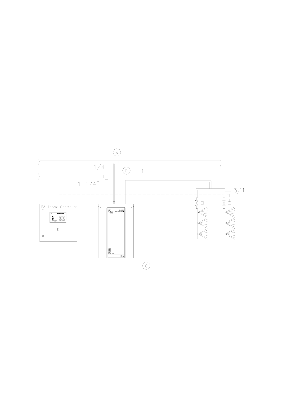
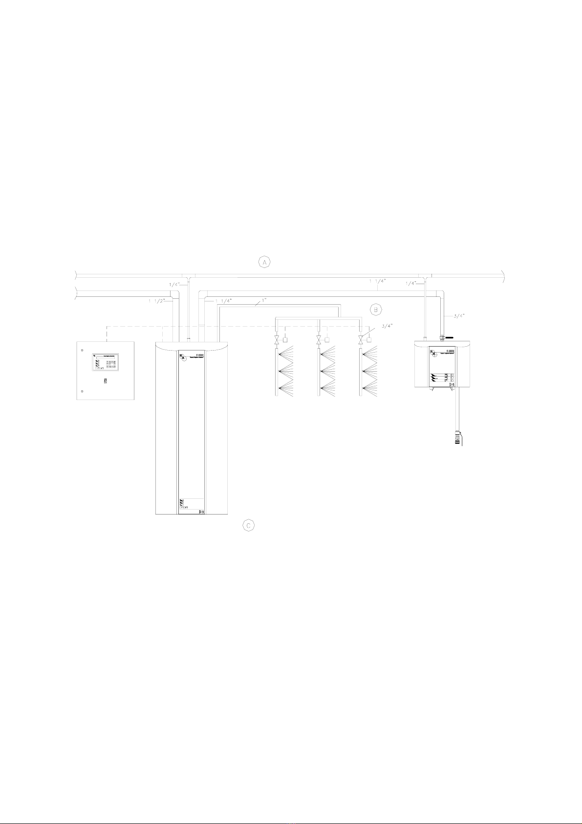
S 6000 and S 5000 are stationary cleaning stations designed to automatic cleaning.
Furthermore, manual S 3000 satellites can be connected to the S 6000. S 5000 is to be
connected to a main/pump station. We recommend the P3 Topax Hygiene Controller to
control the hygiene-cycles. The stations are made of corrosion resistant materials,
mainly stainless steel, and are therefore especially suitable for application within the
food industry. If you need further information, please contact Henkel-Ecolab.
Standard programmable hygiene stages are as follows:
a) pre-rinse with water
b) clean with foam
c) rinse off with water
d) sanitise with spray or foam
e) final rinse with water
1.1 Special Warnings
The special warnings CAUTION, ATTENTION and NOTE used in this Technical
Manual have the following meanings:
CAUTION: This term is used to highlight the fact that complete or even partial
failure to properly adhere to operating instructions, working
instructions, specified working sequences and similar can cause
personal injuries or accidents.

Vers. 1.0 - 17.01.97
2
ATTENTION: This term is used to highlight the fact that complete or even partial
failure to properly adhere to operating instructions, working
instructions, specified working sequences and similar can cause
damage to the equipment.
NOTE: This term is used to draw attention to a particular feature.
1.2 Safety Instructions
S 6000 must only be connected to a 380 VAC supply. S 5000 must only be connected
to a 24 VDC supply. Repairs of the main station must only be carried out when it has
been turned off and depressurised.

Vers. 1.0 - 17.01.97 3
2. Product Survey
2.0 Guidelines for Pipe Connections
S 5000
17047
Fig. 2.0.1
(A) Air supply min. 6 bar and 200 l/min.
(B)1”, max. length 40 m.
(C) Water supply max. 25 bar and min. 12 bar, max. temperature 70°C. Pipe dimensions min. 1 1/4”.
S 6000

Vers. 1.0 - 17.01.97
4
17046
Fig. 2.0.2
(A) Air supply min. 6 bar and 200 l/min.
(B) 1”, max. length 40 m.
(C) Water supply max. 4 bar and min. 2 bar, max. temperature 70°C. Pipe dimensions min. 1 1/2”.
2.1 Basic Unit S 5000

Vers. 1.0 - 17.01.97 5
The basic satellite station consists of a S 5000 inclusive of the accessory listed in
section 2.2. The P3 Topax User Pack, automatic valves and nozzle-stations are non-
standard accessories and should therefore be ordered and purchased separately.
2.2 Accessories
The station is equipped with the following standard accessory:
17057
Fig. 2.2.1
1. Wall bracket

Vers. 1.0 - 17.01.97
6
2.3 Basic Unit S 6000
The basic main station consists of a S 6000 inclusive of the accessory listed in
paragraph 2.4. The P3 Topax User Pack, automatic valves and nozzle-stations are
non-standard accessories and should thus be ordered and purchased separately.
2.4 Accessories
The main station is equipped with the following standard accessory:
17058
Fig. 2.4.1
1. Wall bracket

Vers. 1.0 - 17.01.97 7
3. Description of Function
3.0 Flow Charts
S 5000
Fig. 3.0.1
(A) Water.
(B) Air.
(C) Outlet.
(D) Sanitising.
(E) Detergent.
07051
1-3. Ball valves with pneumatic actuator 13. Non-return valve for air
4. Injector 14. Solenoid valve
5. Dosing valve for sanitising 15. Filter/gauge/adjustment - air
6. Non-return valve for sanitising 16. Non-return valve for air
7. Filter for sanitising 17. Air inlet valve
8. Injector 18-20. Pilot valves
9. Dosing valve for detergent 21. Solenoid valve
10. Non-return valve for detergent 22-23. Non-return valves, rinse
11. Filter for detergent water injectors
12. Injector, air

Vers. 1.0 - 17.01.97
8
S 6000
Fig. 3.0.2
(A) Water.
(B) Air.
(C) Outlet.
(D) Sanitising.
(E) Detergent.
07050
1. Water inlet valve 16. Non-return valve for detergent
2. Filter 17. Filter for detergent
3. Flow switch 18. Injector, air
4. Pump 19. Non-return valve for air
5. Gauge, water pressure 20. Solenoid valve
6. Non-return valve for water 21. Filter/gauge/adjustment - air
7-9. Ball valves with pneumatic 22. Non-return valve for air
actuator 23. Air inlet valve
10. Injector 24-27. Pilot valves
11. Dosing valve for sanitising 28. Solenoid valve
12. Non-return valve for sanitising 29-30. Non-return valves, rinse water injector
13. Filter for sanitising 31. Ball valve with pneumatic actuator
14. Injector (option)
15. Dosing valve for detergent

Vers. 1.0 - 17.01.97 9
3.1 Electric Diagrams
S 5000
01094
Fig. 3.1.1

Vers. 1.0 - 17.01.97
10
S 5000D
01095
Fig. 3.1.2

Vers. 1.0 - 17.01.97 11
S 6000
01096
Fig. 3.1.3

Vers. 1.0 - 17.01.97
12
S 6000 D
01097
Fig. 3.1.4

Vers. 1.0 - 17.01.97 13
3.2 Function of P3 User Pack System (accessory)
Principle of operation
The P3 User Pack is pushed into the holder under the station. The wide bracket on the
right is intended for P3 Topax detergent and the narrow bracket on the left for P3 Topax
sanitising. The suction pipe, which is fixed inside the lid, guides the product to the
injector where it is mixed in the mixing chamber.
The level of P3 Topax product is indicated on the outside level tube.
CAUTION!
When changing between different products in the P3 User Pack, the cans must be
rinsed thoroughly with clean water. Further, the injector must be rinsed.
17027
Fig. 3.2.1
4. Installation

Vers. 1.0 - 17.01.97
14
4.0 Directions for Mounting
ATTENTION!
a) The stations should be mounted in frost-free rooms only.
b) The station can be mounted on a wall or on a separate frame , which can be
installed in production areas and anchored to the floor.
For mounting on walls please note the following:
1. The wall for mounting should be either a stable brick or a wall made of
concrete.
2. The delivered bracket should be secured to the wall by the enclosed screws
and corresponding dowels.
c) The mounting holes for the wall bracket must be drilled according to the
dimensional sketches on pages 15 and 16.
d) The wall bracket must be mounted on the wall as described on pages 15 and
16. Afterwards the station is installed on the bracket. Mount the delivered angle
hinges on the rear part of the pump plate ensuring that the lower part of the
frame is fastened.
e) S 6000 is delivered with two transport fittings, which must be removed after the
station has been mounted on the wall bracket.

Vers. 1.0 - 17.01.97 15
Mounting of S 5000
17034
Fig. 4.0.1

Vers. 1.0 - 17.01.97
16
Mounting of S 6000
17031
Fig. 4.0.2
This manual suits for next models
1
Table of contents