manuals.online logo
Brands
  1. Home
  2. •
  3. Brands
  4. •
  5. Aluprof
  6. •
  7. Control Unit
  8. •
  9. Aluprof AL-BR01 User manual

Aluprof AL-BR01 User manual

1
We reserve the right to any technical change.
Valid on 2019.11.18
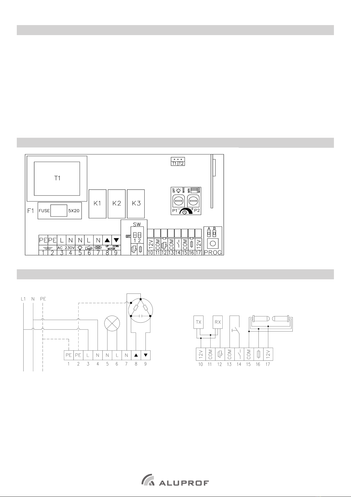
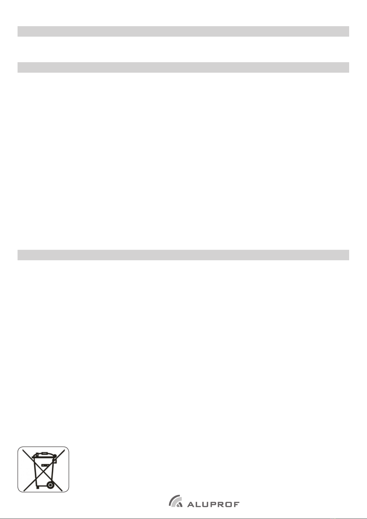
INSTALLATION, ASSEMBLY AND OPERATING MANUAL FOR THE GATE CONTROL UNIT ALBR01
Failure to comply with this Manual may result in injury or death.
Keep the Manual for reference.
1. Installation safety
NOTE: Follow these instructions: non-compliant installation and/or removal may cause severe injury!
- Read this Manual before installing the product.
- Have this control unit installed/removed and wired by a suitably licensed electrician (with an electrician’s license for electrical installations ≤ 1 kV).
- Caution: Disconnect the power cable from the supply voltage before removing the product.
- The control unit is intended for operation in dry indoor rooms. Do not expose it to weather.
- The control unit requires a separate power supply line, connected to the power sub-distribution switchboard with a short-delay current breaker,
e.g. a B10 over-current CB.
- If the control unit power cable is damaged, replace it.
- Fasten and route the power cable to prevent the condensate (water) from flowing into the control unit enclosure.
- A single control unit must not operate more than one drive unit
- Install the control switch at a safe distance from all moving parts of the roller shutter / gate and at a distance which will permit watching the
operation of the roller shutter / gate, and at least 1.5 m above the floor (the minimum height above the floor requirement does not apply to key-
operated switches).
- After installation, make sure that the gate / roller shutter inverts directions properly.
- The installer must comply with the standards and regulations in force in the country where the installation is carried out.
- Users should be trained to operate the control unit.
2. Safety of control unit operation and maintenance
NOTE: Follow these instructions: non-compliant operation and/or maintenance may cause severe injury!
- Keep children away from the central unit and its controls: they are not toys.
- Isolate the power supply from the control unit before cleaning, maintenance or replacement of parts.
- Do not operate the control unit if it needs to be repaired or readjusted.
- Whenever the roller shutter / gate is running there must be no obstacles on its way until is completely closed or open.
- Test the control unit for proper reversing of the sense of rotation at least every month.
- Do not attempt to open the roller shutter / gate if it is stuck with heavy ice.
- Do not attempt to alter or modify the product without authorization; otherwise your product warranty will be void and the product may become
hazardous in use. Have all maintenance and repairs done by a qualified technical service provider, the manufacturer, or the manufacturer’s
authorized agent.
In accordance with the provisions of the Directive of the European Parliament and of the Council 2012/19 / EU of 4 July 2012 on waste electrical
and electronic equipment (WEEE), it is prohibited to place of used equipment together with other wastes, marked with crossed out wheeled bin
symbol. The users are obliged to transfer their used equipment to a designated collection point for proper processing. The marking means, at the
same time, that the equipment was put on the market after 13 August 2005. These legal obligations have been introduced to reduce the amount
of waste generated from waste electrical and electronic equipment and to ensure an appropriate level of collection, recovery and recycling. The
equipment does not contain any dangerous components, which would have any particularly negative impact on the environment and human
health.
2We reserve the right to any technical change.
Valid on 2019.11.18
3. Technical specications.
input / output AC
 Power supply: ~230V/50Hz
- power consumption: 0,4 W
- fuse: 250VAC / 4A
- works with motors up to 230 Nm
 Frequency: 433.92 Mhz
- up to 12 transmitters can be programmed
- Operating temperature: ~ -20°C ~ +55°C
- Average range: 200 meters (in open space)
35 meters (inside buildings)
- Dimensions: 150x100x70 mm
Company reserves the tolerance of catalog data due the different conditions usage.
Works with S, BD and M versions of tubular motors and can match all DC remote controllers..
4.1. Wiring diagram.
input / output DC
1, 2. protective wire
3. 230V AC supply – L wire (phase)
4. 230V AC supply – N wire (neutral)
5. Lighting supply – N wire (neutral)
6. Lighting supply – L wire (phase)
7. Drive supply – N wire (joint)
8. Drive supply – L1 wire (UP direction)
9. Drive supply – L2 wire (DOWN direction)
10, 11. Photocell supply 12V DC)
12. Photocell input (NC)
13, 14. External button (monostable)
15, 17. Optical bar supply (12V DC)
16. Optical bar input.
4. layout of the elements
T1 - power transformer
F1 - fuse: 250VAC / 4A
K1, K2, K3 - relays
P1 - potentiometer (lighting operation time)
P2 - potentiometer (drive operation time)
1-9 - input / output AC
10 - 17 - input / output DC
SW1 - DIP 1 - photocell connection
SW2 - DIP 2 - optical bar connection
PROG - programming button
T1, T2 - photocell jumper
Radio
3
We reserve the right to any technical change.
Valid on 2019.11.18
5. Control unit programming.
5.1. Programming the rst transmitter.
With the power on, press the
PROG button or 3x the button
connected to inputs 13 and
14 which will be confirmed by
lighting of the A LED.
Within 10 seconds press the
„P2” button *
Correct programming of the
transmitter will be confirmed by
lighting of the LED B and short
supply of voltage to outputs
5 and 6
* - In case of lack of‚’P2’’button its function is performed by a combination of “STOP” and “UP” buttons.
5.2. Adding another transmitter.
Press the„P2” * button twice
of the already programmed
transmitter
Press the ”P2”* button of the
new transmitter
Each button press will be
confirmed by lighting of the
LED B and short voltage supply
to outputs 5 and 6
* - In case of lack of‚’P2’’button its function is performed by a combination of “STOP” and “UP” buttons.
5.3. Deleting the transmitter.
Press the „P2” button* Press the „STOP” button Press the „P2” button*
* - In case of lack of‚’P2’’button its function is performed by a combination of “STOP” and “UP” buttons.
5.4. Return to factory settings.
Returning to factory settings deletes all the transmitters programmed in the control unit.
With the power on, press the
PROG button 7x
Each button press will be
confirmed by lighting LED A
Successfully completed
procedure will be confirmed by
lighting of LED A, LED B
Each button press will be
confirmed by lighting of the
LED B and short voltage supply
to outputs 5 and 6
4We reserve the right to any technical change.
Valid on 2019.11.18
6. Conguration.
6.1. Lighting connection and control.
The lighting should be connected to terminals 5 and 6. Working time is adjusted by the P1 potentiometer (range from 0 to 180 seconds - 15 seconds
6.2. Drive connection and control.
The drive should be connected to terminals 7, 8 and 9, where terminal 7 is common to both directions of movement.
P2 potentiometer adjusts working time (range from 6 to 180 seconds - 15 seconds step).
The control unit can be controlled by any DC series transmitter or monostable button connected to terminals 13 and 14 (operates in the sequence
UP - STOP - DOWN - STOP).
6.3. Photocell connection.
DIP switch SW1 should be set to ON position.
The photocell must be connected in NC mode (normally shorted) to terminals 10, 11 and 12 (see diagram in section 4.1).
Photocell error is signaled by a flashing red LED under terminal No. 12.
The error may occur in the case of:
1. no connection,
2. photocells damage ,
3. collision.
NOTE:
In accordance with standard EN 12453 governing the safe use of motorised doors, control of the garage door not visible to the user requires the
installation of a photoelectric cell type safety device and/or optical bar.
NOTE:
The gate will be disabled if an error occurred
6.4. Optical bar connection.
DIP switch SW2 should be set to ON position.
The optical bar must be connected to terminals 15, 16 and 17 (see diagram in section 4.1).
Optical bar error is signaled by a flashing red LED under terminal No. 16.
The error may occur in the case of:
1. no connection,
2. optical bar damage
3. collision.
NOTE:
In accordance with standard EN 12453 governing the safe use of motorised doors, control of the garage door not visible to the user requires the
installation of a photoelectric cell type safety device and/or optical bar.
NOTE:
The gate will be disabled if an error occurred
step). When opening and closing the gate lighting is automatically switched on, when gate is not operated lighting can be activated by pressing
Pin jumper T1 Pin jumper T2
NOTE:
Required setting for rolling grilles control.
NOTE:
Automatic control of lighting can be disable by setting potentiometer to „0” position and lighting can be turned on / off using the STOP button..
Activation of the safety device during
closing will automatically cause move in
opening direction
Activation of the safety device during
opening / closing stops the operation of
the gate.
STOP button.

Other Aluprof Control Unit manuals

Aluprof AC 277-01 Owner's manual

Aluprof

Aluprof AC 277-01 Owner's manual

Aluprof AL-BR02 User manual

Aluprof

Aluprof AL-BR02 User manual

Popular Control Unit manuals by other brands

Vansco VMM3120 user guide

Vansco

Vansco VMM3120 user guide

WAGO 750-363/0040-0000 manual

WAGO

WAGO 750-363/0040-0000 manual

Farfisa Alba Series manual

Farfisa

Farfisa Alba Series manual

Inficon IO1000 Translation of the original operating instructions

Inficon

Inficon IO1000 Translation of the original operating instructions

Ziton ZPR868 Installation guide / instruction manual

Ziton

Ziton ZPR868 Installation guide / instruction manual

ABB MRP31.0 manual

ABB

ABB MRP31.0 manual

FrSky R9M Lite Pro instruction manual

FrSky

FrSky R9M Lite Pro instruction manual

Pepperl+Fuchs PXV Series quick start guide

Pepperl+Fuchs

Pepperl+Fuchs PXV Series quick start guide

Nice WM100 Instructions and warnings for installation and use

Nice

Nice WM100 Instructions and warnings for installation and use

LOVATO ELECTRIC RGK800SA instruction manual

LOVATO ELECTRIC

LOVATO ELECTRIC RGK800SA instruction manual

Chamberlain K1A6424-2 manual

Chamberlain

Chamberlain K1A6424-2 manual

Bosch Rexroth VM350 operating instructions

Bosch

Bosch Rexroth VM350 operating instructions

Pilz PSSu E F BSW operating manual

Pilz

Pilz PSSu E F BSW operating manual

Nautel NxLink Technical instruction manual

Nautel

Nautel NxLink Technical instruction manual

RS PRO 209-6356 Instruction leaflet

RS PRO

RS PRO 209-6356 Instruction leaflet

SCHNERZINGER COMPONENT GUARD quick start guide

SCHNERZINGER

SCHNERZINGER COMPONENT GUARD quick start guide

National Instruments 9759 user manual

National Instruments

National Instruments 9759 user manual

Omron CS1W-213 - REV 02-2008 Operation manual

Omron

Omron CS1W-213 - REV 02-2008 Operation manual

manuals.online logo
manuals.online logoBrands
  • About & Mission
  • Contact us
  • Privacy Policy
  • Terms and Conditions

Copyright 2025 Manuals.Online. All Rights Reserved.