Alutech CUR User manual

CUR
www.alutech-group.com
ІНСТРУКЦІЯ З ЕКСПЛУАТАЦІЇ
Радіоприймач Українська
Odbiornik radiowy
INSTRUKCJA OBSŁUGI Polski
Receiver
OPERATION MANUAL
NOTICE
Récepteur radio
Радиоприёмник
РУКОВОДСТВО ПО ЭКСПЛУАТАЦИИ
BEDIENUNGSANLEITUNG
Funkempfänger
Русский
Français
Deutsch
English

75°
75°
39
127
=
2
34
90°
=
6.3A/ 250V
FU
D
PB
T1
T2
1
CB
2

5
6 7
8 9
3

FLL2L1NN
L
AC 230V/ 1500W max.
230V/ 100W max.
DC +12V
max. 100mA
AC 230V/ 50Hz
M
M
SBS
RX
+
–
COM
NC
TX
+
–
PH
SE
+12V
SBS
PН
SE
+12V
white
brown
greengreengreen
10
a
(NO)
(NC)
SBSPHSE
+12V
GND
GND
SBS
PH
SE
+12V
GND
SBS
PH
SE
+12V
GND
SBS
PH
SE
+12V
GND
SBS
PH
SE
+12V
GND
SBS
PH
SE
+12V
GND
GND
b
c
d
f
e
g
4

English
5
1. GENERAL INFORMATION AND SAFETY INSTRUCTIONS
Before installation, please read carefully all the information below and follow all the instructions in the manual. Save this manual
for future reference.
The contents of the manual may not serve as a basis for legal claims.
Unauthorized changes to the product or improper use are not allowed. Intended use includes compliance with the prescribed
operating rules in the manual and legal regulations in the installation region.
The product is not intended for use and storage in acid, saline or explosive environments.
When carrying out work (installation, repair, maintenance, cleaning, etc.), disconnect the product from the mains.
Radio control is allowed only for installation conditions in which radio interference in the transmitter or receiver does not
cause danger to people, animals or objects, or other protective devices prevent the risk.
The product is not protected from interference from other radio devices (for example, radio installations operating in the
same frequency band).
2. INTRODUCTION
Receiver CUR (control unit) is designed to control tubular motors of roller shutter systems protecting window, door and gate
openings with the help of buttons on the case or by means of ALUTECH remote controls. It is permissible to connect addi-
tional control and safety devices to the product, such as pushbutton switches, key switches, photocells, optical and resistive
safety edges.
3. TECHNICAL DATA
Please select the optimal model of tubular motor depending on the power of the product, in accordance with the require-
ments of instructions and recommendations of ALUTECH. If necessary, contact the Supplier for advice.
Technical data
Power supply voltage / Frequency
~230V (+10%, -15%) / 50Hz
Maximum power consumption in standby mode (without additional devices con-
nected)
1.5W
Maximum motor output
1500W
Flashing lamp power supply
~ 230V / max. 100W
Power supply of additional devices (accessories)
12V DC /
max. 100mA
ALUTECH radio frequency
433.92MHz
Number of storable remote controls
250
Protection rating
IP54
Operating temperature
-20ºС … +50ºС
Power supply cable section
max. 2.5mm2(22-14AWG)
Additional devices cable section
Dimension (W x H x D)
150 х 100 х 38mm
Weight
<0.3kg
These specifications refer to an ambient temperature of 20ºC (±5ºC) and a supply voltage of 230V/50Hz.
Please observe the safety instructions specified in the legal regulations applicable in the region where the product is
installed. When operating with automatic closure, it is necessary to comply with the standard EN 12453 for safety de-
vices in the region of operation. Qualified personnel must ensure that after a roller shutter system is commissioned, the
standards in force in the region, for example, EN 13659 standards for roller shutters or EN 12635 for gates, are in force.
Remote control is associated with the risk of injury, and should be performed only with direct visual observation of the
movement of the roller shutter.
The remote control should be stored in such a way as to exclude accidental activation, including by children or animals.
EN

6
4. MOUNTING AND WIRING
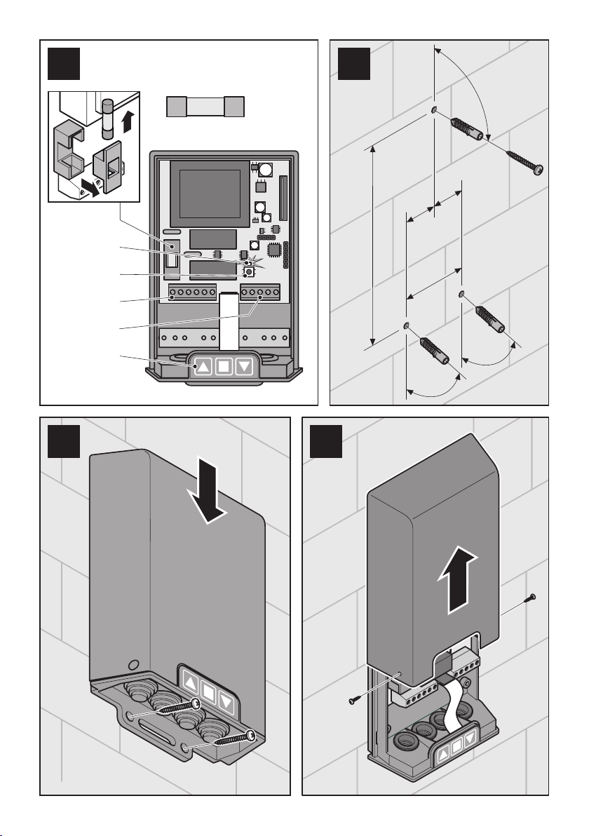
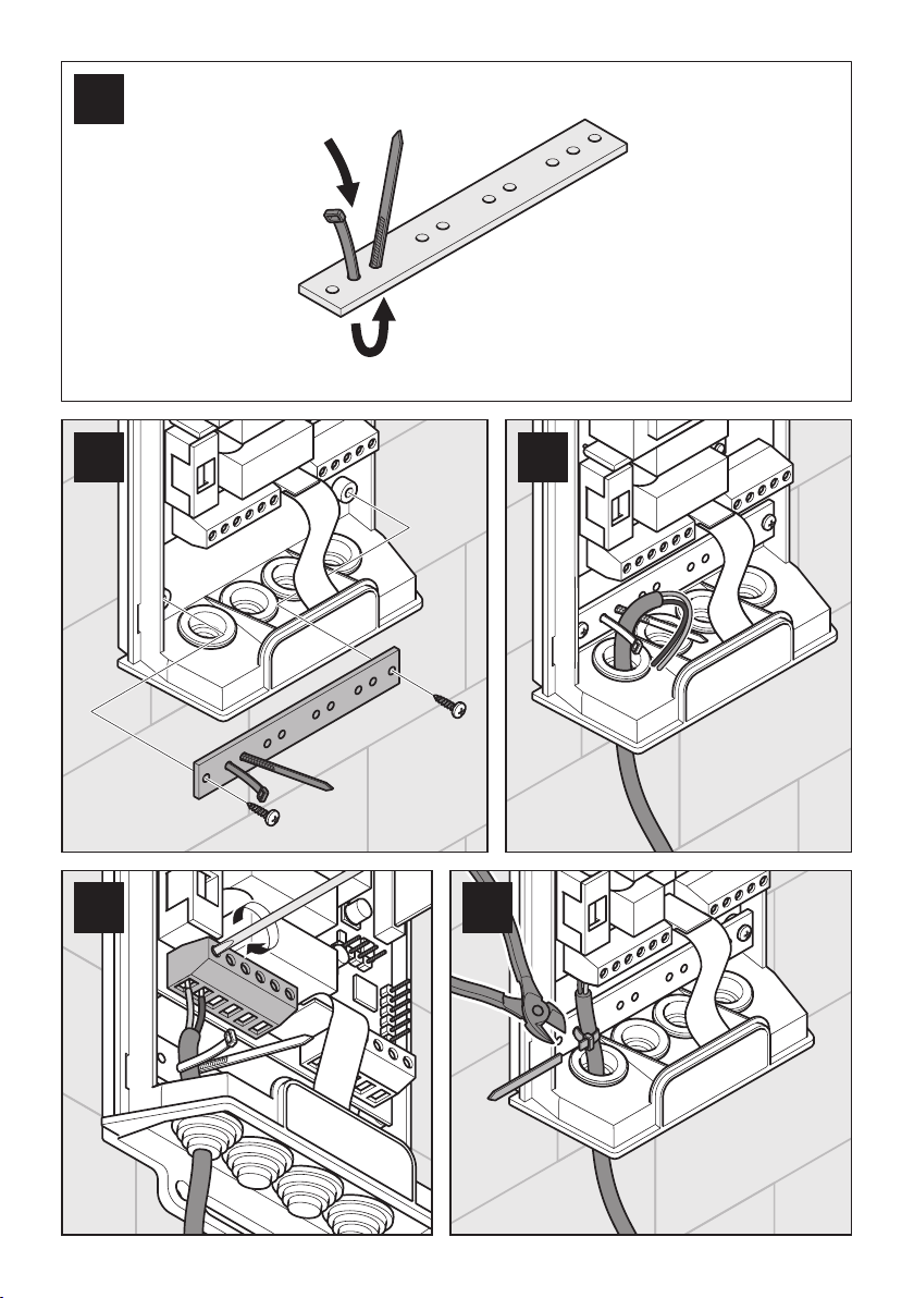
Mounting should be carried out in accordance with the requirements listed below and in the order indicated in the illustrative
part of the manual, see pages 2-3.
The given instructions should be treated as an example, as the installation location of the product and its components may
differ. The installer's task is to select the most suitable solution.
Connect the devices to the control unit terminals according to the wiring diagram (Figure 10).
If the direction of rotation of the actuator output shaft does not match the required direction, disconnect the power supply
and exchange the connection wires on the terminals «L1»and «L2»(Figure 10).
The installation site must be able to receive radio signals of good quality (there are no shielding or reflective surfaces or other
sources of radio emission). The distance between adjacent control units should be not less than 300 mm.
Several motors must not be connected in parallel to the control unit.
Do not shorten or extend the antenna.
Let the mounting, startup and maintenance work be carried out by a competent person (in accordance with EN 12635) in the
area in which it is installed and operated according to the guidelines in this manual. Observe EN 12604 and EN 12635 as well
as other legal regulations in the area in which they apply.
The parameters of electrical cables used (cross section, number of wires, etc.) must correspond to the wiring diagram, device
power, installation distance, installation method and environmental conditions.
When using the product outside (outdoors), the electrical cables must have special protective covers. Cables routed through a
metal partition wall must be protected and isolated.
The product must be located within direct sight of the roller system, at a safe distance from moving parts, at a height of at
least 1.5m. Make sure that the installation sites of the control unit and additional devices (accessories) are protected from im-
pacts and the installation surfaces are strong enough.
When performing any work (installation, repair, maintenance, cleaning, etc.), disconnect the power circuit. If the switching
device that turns off the power is out of sight, attach the label: «Do not turn on! People are working»and take measures that
exclude the possibility of erroneous voltage supply.
Connecting control devices
For control, devices with a «normally open contact»(Figures 10d, 10e) are connected to the «SBS»and «GND»control unit ter-
minals: buttons, switches, external receivers, etc. The control is carried out in the sequence: «open - stop - close - stop -open -
...». If several control devices are installed, they must be connected in parallel.
Do not apply voltage to the «SBS»terminal!
Connection of safety devices - photocells and emergency switch
The selection of the safety devices (operating logic of the «PH»and «SE»connection inputs) in the control unit settings
(see Section 5) must correspond to the connected safety device types!
To stop the roller shutter during opening and closing, devices with a «normally closed contact»are connected to the «PH»and
«GND»terminals (Figures 10a, 10f, 10g). If devices are connected, they must be connected in series.
In order to provide safety during closing, photocells are connected (Figure 10a). The receiver output circuit (RX) must be con-
nected to the «PH»and «GND»terminals. The power supply circuits of the receiver (RX) and the transmitter (TX) of the photo-
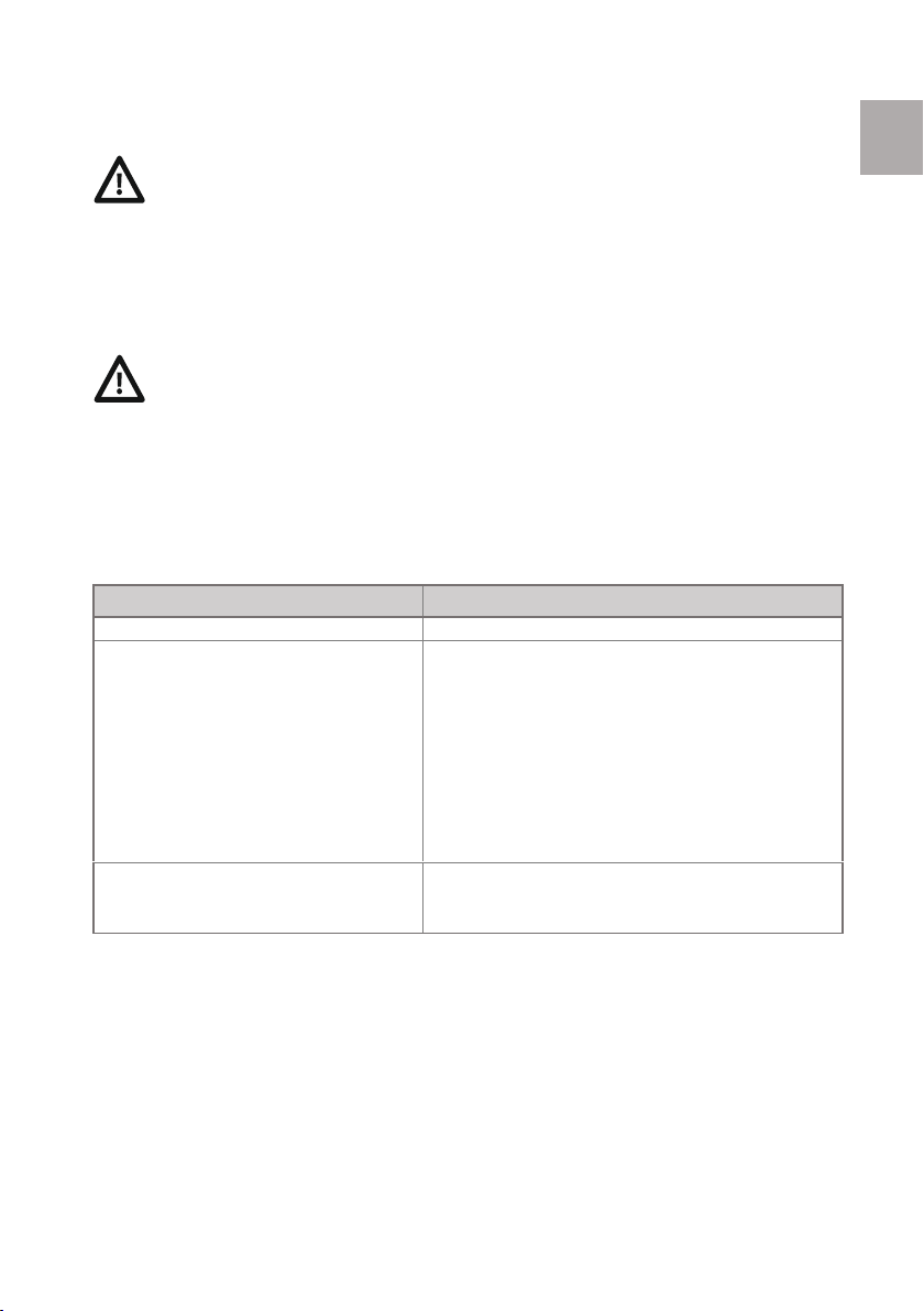
cells are connected to the terminals «+12V»and «GND»with the rated voltage of 12V DC. The maximum current value for all
devices connected to the terminals «+12V»should not exceed 100mA.
During closing, the operation of the photocells causes the movement to stop and then the curtain is completely raised, and
the operation of the photocells again causes the curtain movement to stop. During opening, the operation of the photocells
causes the curtain to stop moving.
Only qualified personnel in accordancewiththe legal acts ofthe region where the product is being installedshould carry out
installation, wiring and commissioning.For example, safety instructions EN60335-2-97 or installation guidelines of the Associa-
tion of German Electrical Engineers (VDE 0100). Qualified personnelmust ensure that after the roller shutter system has been put
into operation, the standardsin force in the region are met, for example, the EN13659 standard for roller shutters or EN 12635 for
the rollergate.
Use the product with care during installation process: protect it from impact, fall or contact with liquids of any type. Do
not place the device near heat sources or place near an open flame. The situations described above may damage the
product, cause malfunctions or lead to danger. If one of the situations described above occurs, immediately stop the
assembly process and contact the service Supplier.
WARNING! The electrical network must be equipped with protective grounding. The electrical network to which the
product is connected must be equipped with a protective device in accordance with the regulations in the region. Con-
nect the ground wire of the motor to the protective ground of the electrical network. The distance between the termi-
nals in the disconnecting device is at least 3mm.
EN

7
If several pairs of photocells are installed, they must be connected in series with each other in the output circuit to the termi-
nals «PH»and «GND»and in parallel to the power supply circuit to the terminals «+12V»and «GND».
For emergency stop of the curtain during opening and closing, an emergency switch and a safety brake can be connected to
the «PH»and «GND»terminals (Figures 10f, 10g). If several emergency devices are installed, they must be connected in series
with each other.
Connection of safety devices - optical or resistive safety edges
To ensure safety during down movement of the curtain (against squeezing or jamming), a safety sensor of the lower edge of
the curtain (safety edge system) is connected to the «SE»input: an 8.2kΩresistive sensor (Figure 10c) or an optoelectronic sen-
sor/optosensors of the OSE system - Signal 12 (Figure 10b).
During the closing of the curtain, the activation of an optoelectronic or resistive sensor causes a stop of movement and the
subsequent full lifting of the curtain.
Connection of safety devices - warning lights
To signal the movement of the web, a flashing light is connected to the «FL»and «N»terminals (Figure 10) 230V / max. 100W,
ALUTECH warning lights are recommended. Flashing light output works without «flashing mode».
5. SELECTION OF SAFETY DEVICE OPERATING MODES
For the operation of the safety devices connected to the inputs «PH» and «SE»(see Section 4), you must select the operating
modes of the inputs in the settings of the control unit.
Procedure
LED D
Press the PB programming button (Figure 1)
lights green with a short blink
Press the ■key on the CB keypad
(Press the button ■as many times as necessary to
select the required operating mode of the con-
nected safety devices to the inputs «PH»and «SE»)
rarely flashes red:
Single - set the STOP mode for the «PH»input and the 8.2kΩresis-
tive sensor for the «SE»input (factory setting)
twice –set the STOP mode for the «PH»input and the optoelec-
tronic sensor OSE for the «SE»input are set
three times - set the photocell mode for «PH»input and 8.2kΩre-
sistive sensor for «SE»input
four times - set the photocell mode for «PH»input and optoelec-
tronic sensor OSE for «SE»input
Press the PB programming button
(or after ~6 seconds the control unit will automati-
cally memorize the set mode)
rarely flashes green (control unit standby mode)
If no device is connected to terminals «PH»and «GND», then a jumper must be installed. If safety devices are connected
to terminals «PH»and «GND», then remove the jumper.
Do not apply voltage to the «PH»terminal!
If the bottom edge safety sensor is not connected, then a resistor of 8.2kΩ± 5% must be connected to the «SE»and
«GND»terminals and the operating mode with a resistive sensor must be selected in the device safety settings (see Sec-
tion 5). If the bottom edge safety sensor is connected, the resistor should be removed.
EN

8
6. WORKTIME SETTING
The limit settings of the motor should be made before the start of the working time setting procedure. The curtain must be
completely closed.
The maximum working time is 100 seconds (factory setting).
Procedure
LED D
Press the PB programming button (Figure 1)
lights green with a short blink
Press the ▲button on the CB keyboard
flashes red
When fully opened, press ■on the CB keypad
(can be pressed, for example, after ~3 seconds after full opening)
~2 seconds flashing green frequently →rarely flashes
green (control unit standby mode)
7. ADDING AND REMOVING REMOTE CONTROLS (AT-1, AT-1S, AT-15, AT-15S, AT-4N, etc.)
The control with the help of an added remote control is exercised as follows:
For UBS mode - control with three remote control buttons ▲, ■, ▼«open», «stop», «close»respectively.
For SBS mode - control with button of the remote control in the sequence: «open - stop - close - stop - open - ...»
Adding remote controls
LED D
Press the PB programming button (Figure 1)
lights green with a short blink
Press the ▼button on the CB keyboard
(Press the ▼button as many times as necessary to select the re-
quired UBS or SBS control mode.)
flashes red once - UBS control mode
flashes red twice - SBS control mode (factory setting)
Press and release the remote control button
(For the UBS mode - press the button intended for opening, other
buttons are assigned automatically)
~2 seconds lights red →rarely flashes green
Press and release the same remote control button
~2 seconds lights red →rarely flashes green (control
unit standby mode)
If the remote button is reassigned, the recording procedure must be repeated.
Removing all remote controls
LED D
Press and hold (~ 9 seconds) PB programming button (Figure 1)
~ 9 seconds flashes green several times →red several
times →lights red
Release PB Programming Button
lights (~ 2 seconds) green →flashes quickly (~ 3 sec-
onds) red →rare green flashes (control unit standby)
If the button ■is not pressed within 5 seconds after full opening, the control unit will retain the factory setting (100
seconds).
It is recommended to clear the control unit memory from previously recorded remote control codes before the first re-
mote control recording.
If the following action is not performed while adding a remote control unit for 6 seconds, the control unit will go into
standby mode (a rare flashing green light of the control unit indicator). The remote control will not be recorded and
the recording procedure must be performed again.
If the remote control is lost, in order to avoid unauthorized entry it is necessary to delete all remote controls from the
memory of the control unit and add them again.
EN

9
8. OPERATION
The corresponding remote control buttons are responsible for opening, stopping and closing the roller shutter system:
UBS - control with three remote control buttons ▲, ■, ▼correspondingly –«open», «stop», «close».
SBS - control with one remote control button in the following sequence: «open - stop - close - stop - stop - ...».
If the safety device has been triggered, the remote control is not possible. To raise/lower the roller curtain in case of emer-
gency, use the buttons on the control unit body - CB keypad (Figure 1) operating in the dead-hand mode.
Before opening/closing the roller shutters, please make sure that no foreign objects or persons are in the area of the roller
shutter. Watch the movement of the curtain. Keep persons away from the rolling curtain until it is completely closed. Do not
touch moving parts of the roller shutter.
The customer and operators of the product must be instructed about danger and risks involved as well as about rules of safe
operation and maintenance.
Do not use the product in case it requires to be serviced.
Signaling of LED D of the control unit
Description
LED D
The control unit functions in standby mode
lights green with a short blink
Curtain movement
lights red
Safety device triggered or no remote control added
~2 seconds of frequent red flashing
The remote control button not used when adding
~2 seconds of frequent red flashing
Troubles and recommendations for their resolution
Observations
Possible causes
Actions/Troubleshooting
No control unit indication, motor
doesn't work
No mains voltage, badly
clamped wires in terminals,
fuse destroyed.
Check the mains voltage. Tighten the wires
in the terminals. Check and replace the fuse
if necessary (see how to replace the fuse)
Control unit is indicated, motor axis
does not rotate correctly
Wiring Error
Check motor wiring (see Section 4)
The motor is not operated by the re-
mote control (the indicator on the re-
mote control "lights up" and the control
unit indicator ~2 seconds flashes red
frequently)
Safety device has been trig-
gered, or the remote control is
not added to the control unit
memory
Check the operation of the safety devices.
Save the remote control to the control unit
(see Section 7)
The motor is not controlled or does not
react when safety devices are triggered
Wrong selection of safety de-
vice settings or safety device is
faulty
Select the connected safety devices in the
settings (see Section 5). Check the function-
ality of the safety devices, replace them if
necessary
The motor is not controlled by the re-
mote control (the remote control indi-
cator does not light up or is not lit up
brightly)
The remote control battery is
discharged
Check the remote control battery and re-
place it if necessary
The curtain does not stop in end posi-
tions
The end positions are not set
up or are faulty. Incorrect
setting of runtime
Adjust the end positions of the actuator. Re-
adjust the working time of the control unit
(see Section 6)
PROHIBITED! To operate a roller shutter system with defective controls and safety features.
PROHIBITED! To use the product with damaged power cable insulation. If the power cable is damaged, it
must be replaced by the Supplier to avoid danger.
The product is not intended to be used by persons (including children) with reduced physical, sensory or
mental capabilities, or lack of experience or knowledge, unless they are supervised or instructed how to
use the product by a person responsible for their safety.
Adults must supervise children and not allow children to play with the product.
When carrying out any work (installation, repair, window cleaning, etc.), disconnect the power supply
from the product.
If a fault is detected that cannot be fixed using the information in this manual, please contact customer service.
Contact the supplier for information about service.
EN

10
Changing the fuse:
Turn off the power.
Remove the control box cover (Figure 4).
Open the fuse holder cover.
Replace the defective fuse with a similar one: F - 6.3A (Fuse FU, Figure 1).
Put all the items back in place.
Average service life of the product is 8 years with the intensity of work up to 30 cycles of «opening-closing»per day. After the
expiration of the established service life, it is necessary to address to the Supplier for reception of the conclusion on admissi-
bility of the further operation of the product.
9. SERVICE
The control unit must be subjected to scheduled service to ensure efficient and safe operation. Planned service must be car-
ried out in strict compliance with the applicable regulations and safety measures. Planned service must be carried out at least
once a year:
Check the control unit and components (cables, buttons, electronic components, etc.). Damaged parts must be replaced.
Clean the outer surfaces of the control unit. Clean with a soft, damp cloth. Do not use water jets, high-pressure cleaners,
acids or alkalis for cleaning.
Check the proper operation of the controls (control unit buttons, remote controls and optional controls).
Check that the connected motor is working properly.
At least once every six months, check the correct operation of each connected safety and alarm device.
10. WAREHOUSING, TRANSPORTATION AND RECYCLING
Warehousing of products shall be effected in packaging in closed and dry premises. Do not allow exposure to precipitation or
direct sunlight. Storage period is 2 years from the production date. All types of closed aboveground transport can carry out
the transportation with the exception of shocks and movements inside of transport.
Recycling should be performed according to regulatory and legal acts about utilization and recycling used in the
country of consumption. The product does not contain precious metals and substances that are dangerous to life,
health and the environment.
The packaging must be disposed of in accordance with current regulations.
11. WARRANTY
1. The Seller guarantees full operability of the product when it is used in full compliance with the user manual, if the mounting
process is carried out by an Organization that has been authorized by the Supplier.
2. During the warranty period, faults caused by the fault of the Manufacturer or the organization authorized by the Supplier
that installed the product, shall be eliminated by the Supplier.
3. The warranty does not apply in cases involving:
failure to comply with installation, operation and use regulations;
installation, adjustment, repair, reinstallation or modification of the product by persons not authorized by the Supplier;
damage to the product caused by unstable operation of the power supply network or mismatching of the power supply
network with the values set by the Manufacturer;
force majeure (fires, lightning strikes, foods, earthquakes and other natural disasters and emergencies);
occurrence of malfunctions and defects caused by the inoperability of roller shutter systems.
the fields in paragraphs 12 and 13 of this manual are not fully filled in.
Note: parts replaced under warranty become the property of the Supplier.
4. The warranty period is 2 years and is calculated from the date of installation.
EN

11
12. PRODUCT DETAILS
Filled at the time of manufacture of the roller shutter systems.
Serial No. and date of manufacture ____________________________________________________________________
Data of the product label
Details of the Customer (the Consumer) ____________________________________________________________________
_____________________________________________________________________________________________________
Name, address and telephone number of the Customer (the Consumer)
Details of the Supplier (installation organization)_____________________________________________________________
_____________________________________________________________________________________________________
Name, address and telephone number of the Supplier (the installation organization)
13. CERTIFICATE OF INSTALLATION AND ADJUSTMENT
The product has been installed and adjusted according to the applicable requirements and is found fit for service.
Date of installation
_________________________________________
Date, month, year
Signature of the person responsible for the
installation
________________ _______________________
Signature, seal Full name
Signature of the person who accepted the
installation (the Customer)
________________ _______________________
Signature Full name
The manufacturer (manufacturer's authorized representative) reserves the right to make changes to the data specified in
these operating instructions at any time. In individual cases, they may differ from the corresponding version of the product,
but the functional information will not change significantly and will not be invalidated.
The latest operating manuals, conformity documents (certificates/declarations) and other information about the product
can be found at www.alutech-group.com
Made in China
Authorised representative in EU:
ALUTECH SYSTEMS S.R.O.
330 23, Czech Republic, Úherce 165
Tel./ Fax: + 420 374 6340 01
ALUTECH hereby declares that this device conforms to the essential requirements and other relevant pro-
visions of Directive 2014/53/EU. A declaration of conformity is available at www.alute.ch/declaration
Alutech Incorporated LLC
10 Selitskogo str., off 301
220075, FEZ «Minsk», Republic of Belarus
Tel. +375 (17) 345 81 52 / Fax +375 (17) 299 61 11
info@alutech.by
EN

Русский
12
1. ОБЩИЕ ПОЛОЖЕНИЯ И МЕРЫ БЕЗОПАСНОСТИ
Перед началом монтажа внимательно изучите всю приведенную ниже информацию и следуйте всем указаниям руко-
водства. Сохраните данное руководство для дальнейшего использования.
Содержание руководства не может являться основанием для юридических претензий.
Не допускается внесение несанкционированных изменений в изделие или использование не по назначению. Исполь-
зование по назначению включает в себя соблюдение предписанных правил эксплуатации в данном руководстве и
правовых норм в регионе установки.
Изделие не предназначено для использования и хранения в кислотной, соленой или взрывоопасной среде.
При проведении работ (монтаж, ремонт, обслуживание, чистка и т.п.) отключите изделие от электрической сети.
Радиоуправление допускается только для таких условий установки, в которых радиопомехи в передатчике или приём-
нике не вызывают опасность для людей, животных или предметов, либо риск предотвращается другими защитными
устройствами.
Изделие не защищено от помех других радиоприборов (например, радиоустановок, работающих в том же частотном
диапазоне).
2. ОПИСАНИЕ
Радиоприёмник CUR (блок управления) предназначен для управления кнопками на корпусе или посредством пультов
дистанционного управления АЛЮТЕХ (радиопультов) электроприводами роллетных систем, ограждающих оконные,
дверные и воротные проёмы. К изделию допустимо подключения дополнительных устройств управления и безопасно-
сти, таких как: клавишные выключатели, замковые выключатели, фотоэлементы, оптические и резистивные кромки
безопасности.
3. ТЕХНИЧЕСКИЕ ХАРАКТЕРИСТИКИ
Оптимально подбирайте модель электропривода в зависимости от мощности изделия, согласно требованиям ин-
струкций и рекомендаций АЛЮТЕХ. При необходимости обратитесь к Поставщику для консультации.
Технические характеристики изделия
Напряжение питания / Частота тока
~ 230В (+10%, -15%) / 50Гц
Максимальная потребляемая мощность в режиме ожидания (без подклю-
ченных дополнительных устройств)
1,5Вт
Максимальная мощность электропривода
1500Вт
Питание проблесковой лампы
~ 230В / макс. 100Вт
Питание дополнительных устройств (аксессуары)
12В постоянного тока /макс. 100мА
Рабочая частота радиоуправления
433,92МГц
Количество записываемых радиопультов
250 штук
Степень защиты оболочки
IP54
Диапазон рабочих температур
-20ºС … +50ºС
Сечение подключаемых проводов с сетевым напряжением питания
макс. 2,5мм2(22-14AWG)
Сечение подключаемых проводов дополнительных устройств
Габаритные размеры (Д х Ш х В)
150 х100 х38мм
Вес
не более 0,3кг
Приведенные технические характеристики относятся к температуре окружающей среды 20ºС (±5 ºС) и напряжению
питания 230В/50Гц.
Соблюдайте правила безопасности, регламентированные действующими в регионе установки изделия
нормативно-правовыми документами. При эксплуатации с автоматическим закрытием надлежит со-
блюдать стандарт EN 12453 по устройствам безопасности, в регионе его действия. Квалифицированный
персонал должен обеспечить соответствие после запуска в эксплуатацию роллетной системы стандар-
там, действующим в данном регионе, например, стандартам EN 13659 для роллет или EN 12635 для ворот.
Дистанционное управление связано с риском травмы, и должно выполняться только при непосредствен-
ном визуальном наблюдении движения роллетного полотна.
Пульт дистанционного управления должен храниться таким образом, чтобы исключить случайное вклю-
чение, в том числе, детьми или животными.
RU

13
4. МОНТАЖ И ПОДКЛЮЧЕНИЕ
Монтаж выполнить в соответствии c нижеуказанными требованиями и в порядке, указанном в иллюстрационной части
руководства, см. стр. 2-3. Приведенные инструкции необходимо рассматривать в качестве примера, так как место
установки изделия и его компонентов может отличаться. Задача монтажника выбрать самое подходящее решение.
Подключения устройств к клеммам блока управления выполнить в соответствии со схемой подключений (Рисунок 10).
Если направление вращения выходного вала электропривода не совпадает с требуемым, отключите электрическую
сеть и поменяйте местами провода подключения на клеммах «L1» и «L2» (Рисунок 10).
Место установки должно обеспечивать качественный прием радиосигнала (отсутствуют экранирующие и отражающие
поверхности, другие источники радиоизлучения). Расстояние между соседними блоками управления не менее 300мм.
Не допускается параллельно подключать несколько электроприводов к блоку управления.
Не укорачивайте и не удлиняйте антенну.
Поручите выполнение работ по монтажу, вводу вэксплуатацию итехническому обслуживанию компетентному специ-
алисту (всоответствии со стандартом EN 12635, в регионе его действия) согласно указаниям данного руководства. При
этом следует соблюдать требования стандартов EN 12604 иEN 12635 и другие нормативно-правовые нормы, в регионе
их действия.
Параметры применяемых электрических кабелей (сечение, количество проводов и др.) должны соответствовать схеме
подключения, мощности устройств, расстоянию прокладки, способу прокладки и внешним условиям.
При использовании изделия снаружи (на улице) электрические кабели должны быть проведены в специальных защит-
ных кожухах. Кабели, проложенные через металлическую перегородку, должны быть защищены и изолированы.
Изделие должно располагаться в пределах видимости роллеты, на безопасном расстоянии от подвижных частей, на
высоте не менее 1,5м. Убедитесь, что места установки блока управления и дополнительных устройств (аксессуары)
защищены от ударов и поверхности для установки достаточно прочные.
При проведении каких-либо работ (монтаж, ремонт, обслуживание, чистка и т. п.) отключите цепь питания. Если комму-
тационный аппарат отключающий питание находится вне зоны видимости, то прикрепите табличку: «Не включать!
Работают люди» и примите меры, исключающие возможность ошибочной подачи напряжения.
Подключение устройств управления
Для управления к клеммам «SBS» и «GND» блока управления подключаются устройства с «нормально-открытым кон-
тактом» (Рисунки 10d, 10e): кнопки, выключатели, внешние радиоприемники и т.п. Управление осуществляется в после-
довательности: «открыть - стоп – закрыть – стоп – открыть - …». Если установлено несколько устройств управления, то
они должны быть подключены параллельно.
Не допускается подача напряжения на клемму «SBS»!
Подключение устройств безопасности –фотоэлементов и аварийного выключателя
Выбор устройств безопасности (логика работы входов подключений «PH» и «SE») в настройках блока
управления (см. раздел 6) должен соответствовать подключенным типам устройств безопасности!
Для остановки роллетного полотна при открытии и закрытии к клеммам «PH» и «GND» подключаются устройства с
«нормально-закрытым контактом» (Рисунки 10a, 10f, 10g). Если установлено несколько устройств, то они должны быть
подключены последовательно.
Монтаж, подключения и запуск в эксплуатацию должны выполняться квалифицированным персоналом в соот-
ветствии с нормативно-правовыми актами региона, где производится установка изделия. Например, ин-
струкции по безопасности EN 60335-2-97 или правил монтажа Ассоциации немецких инженеров-
электриков (VDE 0100). Квалифицированный персонал должен обеспечить соответствие после запуска в
эксплуатацию роллетной системы стандартам, действующим в данном регионе, например, стандарту
EN 13659 для роллет или EN 12635 для ворот.
Бережно используйте изделие во время его установки: предохраняйте от удара, падения или контакта с
жидкостями любого типа; не размещайте устройство вблизи источников тепла и не располагайте
рядом с открытым огнём. Описанные выше ситуации могут привести к повреждению изделия, вызвать
сбои или привести к опасности. Если произойдет одна из описанных выше ситуаций, немедленно прекра-
тите сборку и обратитесь в сервисную службу Поставщика.
ВНИМАНИЕ! Электрическая сеть должна быть оборудована защитным заземлением. Участок электриче-
ской сети, к которому подключается изделие, должен быть оборудован устройством защиты согласно
нормативно-правовым актам в данном регионе. Соедините заземляющий провод электропривода с за-
щитным заземлением электрической сети. Расстояние между клеммами в устройстве отключения не
менее 3мм.
RU

14
Для обеспечения безопасности при закрытии подключаются фотоэлементы (Рисунок 10a). Выходная цепь приемника
(RX) должна быть подключена к клеммам «PH» и «GND». Цепи питания приемника (RX) и передатчика (TX) фотоэлемен-
тов подключаются к клеммам «+12V» и «GND», номинальное напряжение на которых 12В постоянного тока. Макси-
мальное значение тока для всех подключенных к клеммам «+12V» и «GND» устройств не должно превышать 100мA.
Во время закрытия, срабатывание фотоэлементов вызывает остановку движения и последующее полное поднятие
полотна, повторное срабатывание фотоэлементов вызывает остановку движения полотна. Во время открытия, сраба-
тывание фотоэлементов вызывает остановку движения полотна.
Если установлено несколько пар фотоэлементов, то они должны быть соединены друг с другом последовательно по
выходной цепи к клеммам «PH» и «GND»и параллельно по цепи питания к клеммам «+12V» и «GND».
Для аварийной остановки полотна при открытии и закрытии к клеммам «PH» и «GND» могут быть подключены аварий-
ный выключатель, инерционный тормоз (Рисунки 10f, 10g). Если установлено несколько аварийных устройств, то они
должны быть соединены друг с другом последовательно.
Подключение устройств безопасности – оптической или резистивной кромок безопасности
Для обеспечения безопасности при закрытии проёма (сдавливание, защемление) к входу «SE» подключается датчик
безопасности нижней кромки полотна (система чувствительный край): резистивный датчик 8,2кОм (Рисунок 10c) или
оптоэлектронный датчик /оптосенсоры системы OSE - Signal 12 (Рисунок 10b).
Во время закрытия полотна, срабатывание оптоэлектронного или резистивного датчика вызывает остановку движения
и последующее полное поднятие полотна.
Подключение устройств безопасности – сигнальной лампы
Для сигнализации о движении полотна к клеммам «FL» и «N» подключается проблесковая лампа (Рисунок 10)230В/макс.
100Вт, рекомендуются сигнальные лампы АЛЮТЕХ. Выход проблесковой лампы работает без «режима мигания».
5. ВЫБОР РЕЖИМОВ РАБОТЫ УСТРОЙСТВ БЕЗОПАСНОСТИ
Для работы подключенных к входам «PH» и «SE» устройств безопасности (см. раздел 4) необходимо в настройках блока
управления сделать выбор режимов работы входов.
Последовательность действий
Индикатор D
Нажать кнопку программирования PB (Рисунок 1)
горит зеленым с коротким миганием
Нажать кнопку ■на клавиатуре CB
(Нажимать кнопку ■нужное количество раз для
выбора необходимого режима работы подклю-
ченных устройств безопасности к входам «PH» и
«SE»)
редко мигает красным:
однократно - режим СТОП для входа «PH» и резистивный
датчик 8,2кОм для входа «SE» (Заводская установка)
двукратно - режим СТОП для входа «PH» и оптоэлектронный
датчик OSE для входа «SE»
трёхкратно - режим фотоэлементы для входа «PH» и рези-
стивный датчик 8,2кОм для входа «SE»
четырёхкратно - режим фотоэлементы для входа «PH» и
оптоэлектронный датчик OSE для входа «SE»
Нажать кнопку программирования PB
(или через ~6 секунд блок управления автомати-
чески запомнит установленный режим)
редко мигает зеленым (режим ожидания блока управления)
Если к клеммам «PH» и «GND» никакие устройства не подключены, то должна быть установлена перемыч-
ка. Если к клеммам «PH» и «GND» подключены устройства безопасности, то удалите перемычку.
Не допускается подача напряжения на клемму «PH»!
Если датчик безопасности нижней кромки не подключен, то к клеммам «SE» и «GND» должен быть подклю-
чен резистор 8,2кОм±5% и в настройках устройств безопасности выбран режим работы с резистивным
датчиком (см. раздел 5). Если датчик безопасности нижней кромки подключен, удалите резистор.
RU

15
6. УСТАНОВКА РАБОЧЕГО ВРЕМЕНИ
До начала процедуры установки рабочего времени должны быть настроены конечные положения электропривода.
Полотно должно быть полностью закрыто.
Максимальное рабочее время – 100 секунд (заводская установка).
Последовательность действий
Индикатор D
Нажать кнопку программирования PB (Рисунок 1)
горит зеленым с коротким миганием
Нажать кнопку ▲на клавиатуре CB
мигает красным
После полного подъёма полотна нажать ■на клавиатуре CB
(допускается нажать, например, через ~3 секунды после полного
открытия)
~2 секунды частое мигание зеленым →
редкое мигание зеленым (режим ожидания
блока управления)
7. ЗАПИСЬ И УДАЛЕНИЕ РАДИОПУЛЬТОВ (АТ-1, АТ-1S, АТ-15, АТ-15S, AT-4N и др.)
Управление с записанного радиопульта осуществляется:
для режима UBS - управление тремя кнопками радиопульта ▲, ■, ▼соответственно – «открыть», «стоп», «закрыть».
для режима SBS управление одной кнопкой радиопульта в последовательности: «открыть - стоп – закрыть – стоп –
открыть - …».
Запись радиопульта
Индикатор D
Нажать кнопку программирования PB (Рисунок 1)
горит зеленым с коротким миганием
Нажать кнопку ▼на клавиатуре CB
(Нажимать кнопку ▼нужное количество раз для выбора необхо-
димого режима управления UBS или SBS)
мигает красным один раз - режим управле-
ния UBS
мигает красным два раза - режим управле-
ния SBS (Заводская установка)
Нажать и отпустить кнопку радиопульта
(Для режима UBS –нажать кнопку предназначенную для открытия,
остальные кнопки назначаются автоматически)
~2 секунды горит красным →горит зеле-
ным с коротким двойным миганием
Нажать и отпустить ту же кнопку радиопульта
~2 секунды горит красным →редкое мига-
ние зеленым (режим ожидания)
При переназначении кнопки радиопульта необходимо заново выполнить процедуру записи.
Удаление всех радиопультов
Индикатор D
Нажать и удерживать (~9 секунд) кнопку программирования PB
(Рисунок 1)
~9 секунд мигает несколько раз зеленым →
несколько раз красным →горит красным
Отпустить кнопку программирования PB
горит (~2 секунды) зеленым →часто мигает
(~3 секунды) красным →редкое мигание
зеленым (режим ожидания блока управле-
ния)
Если в течение 5 секунд после полного открытия не будет нажата кнопка ■, то блок управления сохранит
заводскую установку (100 секунд).
Рекомендуется перед первой записью радиопультов, очистить память блока управления от записанных
ранее кодов радиопультов.
Если при записи радиопульта в течение 6 секунд не будет выполнено следующее действие, то блок управ-
ления перейдет в режим ожидания (редкое мигание зеленым цветом индикатора блока управления). Радио-
пульт записан не будет и процедуру записи необходимо выполнить сначала.
Если радиопульт утерян, во избежание несанкционированного проникновения, необходимо удалить все
радиопульты из памяти блока управления и заново их записать.
RU

16
8. ЭКСПЛУАТАЦИЯ
Соответствующие кнопки радиопульта отвечают за открытие, остановку, закрытие роллетной системы:
UBS - управление тремя кнопками радиопульта ▲, ■, ▼соответственно – «открыть», «стоп», «закрыть».
SBS - управление одной кнопкой радиопульта в последовательности: «открыть - стоп – закрыть – стоп - …».
Если сработало устройство безопасности управление с помощью радиопульта невозможно. Для аварийного подня-
тия/опускания роллетного полотна используйте кнопки на корпусе блока управления - клавиатуру CB (Рисунок 1),
работающую в режиме «мертвой руки».
Перед открытием/закрытием роллеты убедитесь в том, что посторонние предметы и люди не находятся в зоне движе-
ния роллетного полотна. Наблюдайте за движением полотна. Не допускайте людей к роллетам до их полного закрытия.
Не прикасайтесь к движущимся частям роллеты.
Владелец и лица, эксплуатирующие изделие, должны быть проинструктированы о существующих опасностях и рисках,
о правилах безопасной эксплуатации и обслуживания.
Не допускается использовать изделие, подлежащее ремонту.
Сигнализация индикатора D блока управления
Описание
Индикатор D
Блок управления работает в режиме ожидания
горит зеленым с коротким миганием
Движение полотна
горит красным
Сработало устройство безопасности или не записан радиопульт
~2 секунды частое мигание красным
Нажата кнопка радиопульта не использованная при записи
~2 секунды частое мигание зеленым
Неисправности и рекомендации по их устранению
Неисправность
Вероятная причина
Рекомендации
Нет индикации блока управления,
электропривод не работает
Отсутствует напряжение в
сети, плохо зажаты провода в
клеммах, перегорел предо-
хранитель
Проверьте напряжение в сети. За-
жмите провода в клеммах. Проверьте
и замените, в случае необходимости,
предохранитель (см. порядок замены
предохранителя)
Есть индикация блока управления,
электропривод вращается неверно
Ошибка в электрических
подключениях
Проверьте подключения электропри-
вода (см. раздел 4)
Электропривод не управляется радио-
пультом (индикатор на пульте «заго-
рается», а индикатор блока управле-
ния ~2 секунды часто мигает красным)
Сработало устройство без-
опасности или радиопульт не
записан в память блока управ-
ления
Проверьте работу устройств безопас-
ности. Запишите радиопульт в память
блока управления (см. раздел 7)
Электропривод не управляется или не
реагирует при срабатывании
устройств безопасности
Неверный выбор в настройках
устройств безопасности или
устройства безопасности
неисправны
Выберите в настройках подключен-
ные устройства безопасности (см.
раздел 5). Проверьте работоспособ-
ность устройств безопасности, при
необходимости замените их
Электропривод не управляется от
радиопульта (индикатор на пульте не
загорается или горит не ярко)
Батарейка радиопульта раз-
ряжена
Проверьте батарейку радиопульта,
при необходимости, замените ее
Полотно не останавливаются в конеч-
ных положениях
Конечные положения не
настроены или сбились. Не-
верное установка времени
работы
Настройте конечные положения
электропривода. Переустановите
время работы блока управления (см.
раздел 6)
ЗАПРЕЩАЕТСЯ! эксплуатация роллетных систем с неисправными элементами управления, безопас-
ности.
ЗАПРЕЩАЕТСЯ! использовать изделие с поврежденной изоляцией шнура питания. При поврежде-
нии шнура питания его замену, во избежание опасности, должен производить Поставщик.
Изделие не предназначен для использования лицами (включая детей) с пониженными физически-
ми, чувственными или умственными способностями, или при отсутствии у них жизненного опыта
или знаний, если они не находятся под контролем или не проинструктированы об использовании
прибора лицом, ответственным за их безопасность.
Дети должны находиться под контролем взрослых для недопущения игры с изделием и его управ-
лением.
При проведении работ (монтаж, ремонт, мойка окон и т.п.) отключите электропитание изделия.
RU

17
Порядок замены предохранителя:
Отключить питание.
Снять крышку блока управления (Рисунок 4).
Открыть крышку держателя предохранителя.
Заменить вышедший из строя предохранитель на аналогичный: F – 6,3А (предохранитель FU, Рисунок 1).
Установить все элементы на место.
Средний срок службы изделия 8 лет при интенсивности работы до 30 циклов «открытия-закрытия» в сутки. По
истечении установленного срока службы необходимо обратиться к Поставщику для получения заключения о
допустимости дальнейшей эксплуатации изделия.
9. ОБСЛУЖИВАНИЕ
Блок управления должен подвергаться плановому обслуживанию для гарантии эффективной и безопасной работы.
Плановое обслуживание должно производиться в строгом соответствии с действующими нормативными документами
с соблюдением мер безопасности. Плановое обслуживание производите не менее одного раза в год:
Проверьте элементы блока управления и компонентов (кабели, кнопки, электронные элементы и др.).
Поврежденные элементы должны быть заменены.
Очистите наружные поверхности блока управления. Очистку производите с помощью мягкой влажной ткани.
Запрещено применять для чистки: водяные струи, очистители высокого давления, кислоты или щелочи.
Проверьте надлежащее действие элементов управления (кнопки блока управления, радиопульты,
дополнительные устройства управления).
Проверьте правильность работы подключенного электропривода.
Не реже одного раза в шесть месяцев проверьте правильность работы каждого подключенного устройства
безопасности и сигнализации.
10. ХРАНЕНИЕ, ТРАНСПОРТИРОВКА И УТИЛИЗАЦИЯ
Хранение изделия должно осуществляться в упакованном виде в закрытых сухих помещениях. Нельзя допускать воз-
действия атмосферных осадков, прямых солнечных лучей.
Срок хранения – 2 года с даты изготовления.
Транспортировка может осуществляться всеми видами крытого наземного транспорта с исключением ударов и пере-
мещений внутри транспортного средства.
Утилизация выполняется в соответствии с нормативными и правовыми актами по переработке и утилиза-
ции, действующие в стране потребителя. Изделие не содержит драгоценных металлов и веществ, представ-
ляющих опасность для жизни, здоровья людей и окружающей среды.
Упаковка должна утилизироваться в соответствии с действующими нормами.
11. ГАРАНТИЙНЫЕ ОБЯЗАТЕЛЬСТВА
1. Поставщик гарантирует работоспособность изделия при соблюдении правил его эксплуатации и при выполнении
монтажа изделия монтажной организацией, уполномоченной Поставщиком.
2. В течение гарантийного срока неисправности, возникшие по вине Изготовителя, уполномоченной Поставщиком
организации, осуществлявшей монтаж изделия, устраняются Поставщиком.
3. Гарантия на изделие не распространяется в случаях:
нарушения правил монтажа, эксплуатации изделия и использования не по назначению;
монтажа, настройки, ремонта, переустановки или переделки изделия лицами, не уполномоченными Поставщиком;
повреждений изделия, вызванных нестабильной работой питающей электросети или несоответствием параметров
электросети значениям, установленным Изготовителем;
действия непреодолимой силы (пожары, удары молний, наводнения, землетрясения и другие стихийные бедствия);
возникновения неисправностей и дефектов, обусловленных неработоспособностью роллетных систем.
не полностью заполненных полей п.12, 13 настоящего руководства.
Примечание: замененные по гарантии детали становятся собственностью Поставщика.
4. Гарантийный срок составляет 2 года и исчисляется c даты монтажа.
В случае возникновения неисправности, которая не может быть устранена с использованием информации
из данного руководства, необходимо обратиться в сервисную службу. За информацией о сервисной службе
обратитесь к Поставщику.
RU

18
12. ДАННЫЕ ОБ ИЗДЕЛИИ
Заполняется в момент изготовления роллетных систем.
Заводской номер и дата изготовления ____________________________________________________________________
данные с этикетки изделия
Сведения о заказчике (потребителе) _____________________________________________________________________
_____________________________________________________________________________________________________
наименование, адрес и телефон заказчика (потребителя)
Сведения о поставщике (монтажной организации) ________________________________________________________
_____________________________________________________________________________________________________
наименование, адрес и телефон поставщика (монтажной организации)
13. СВИДЕТЕЛЬСТВО О МОНТАЖЕ И НАСТРОЙКЕ
Изделие смонтировано и настроено в соответствии с установленными требованиями и признано годным для эксплуа-
тации.
Дата монтажа
_______________________________
число, месяц, год
Подпись лица ответственного за монтаж
________________ _______________________
подпись, МП расшифровка подписи
Подпись лица принявшего монтаж (заказчик)
________________ _______________________
подпись расшифровка подписи
Изготовитель (уполномоченный представитель изготовителя) оставляет за собой право вносить изменения в
данные, указанные в настоящем Руководстве по эксплуатации в любое время. В отдельном случае они могут отли-
чаться от соответствующей версии изделия, однако функциональная информация не претерпит существенных
изменений и не станет недействительной.
Актуальное руководство по эксплуатации, документы о подтверждении соответствия (сертификаты/декларации) и
другую информацию об изделии вы можете найти на сайте - www.alutech-group.com
Сделано в Китае
Изготовитель:
ZHEJIANG HILAND TECHNOLOGY CO., LTD.
ЧЖЭЦЗЯН ХАЙЛАНД ТЕХНОЛОДЖИ КO., ЛТД.
БИОЛОГИЧЕСКИЙ ИНДУСТРИАЛЬНЫЙ ПАРК ЮНИОНГИН, ЙОНГЧЖАН РОУД 128,
ДАЙПУ, АНЖИ, ХУЧЖОУ, ЧЖЕЦЗЯН, КИТАЙ, 313000
Импортер в Республике Беларусь/Уполномоченный представитель изготовителя:
ООО «Алютех Инкорпорейтед»,
220075, Беларусь, Минская область, Минский район, СЭЗ «Минск», ул. Селицкого 10-301
Тел. +375 (17) 299 61 11, 345 81 52
ООО «Алютех Инкорпорейтед»
ул. Селицкого, 10-301
220075, Республика Беларусь, СЭЗ «Минск»
Тел. +375 (17) 345 81 52
Факс +375 (17) 299 61 11
info@alutech.by
RU

Deutsch
19
1. ALLGEMEINE VORSCHRIFTEN UND SICHERHEITSMAßNAHMEN
Lesen Sie vor Beginn der Montage die folgenden Informationen sorgfältig durch und befolgen Sie alle Anweisungen in der
Anleitung. Bewahren Sie diese Anleitung zum späteren Nachschlagen auf.
Der Inhalt dieser Anleitung kann keine Rechtsansprüche begründen.
Unbefugte Veränderungen am Produkt oder zweckfremde Verwendung sind nicht gestattet.
Zur zweckbedingten Verwendung gehört die Beachtung der in dieser Anleitung vorgeschriebenen Betriebsvorschriften sowie
der gesetzlichen Vorschriften in der Einsatzregion.
Das Produkt ist für den Einsatz und Lagerung in einer sauren, salzhaltigen oder explosiven Umgebung nicht bestimmt.
Trennen Sie das Gerät vom Stromnetz, wenn Sie Arbeiten (Montage, Reparatur, Wartung, Reinigung u.ä.) durchführen.
Die Funksteuerung ist nur unter den Installationsbedingungen zulässig, bei denen Funkstörungen im Sender oder Empfänger
keine Gefahr für Menschen, Tiere oder Gegenstände darstellen bzw. das Risiko durch sonstige Schutzeinrichtungen verhindert
wird.
Das Produkt ist nicht gegen Störungen durch andere Funkgeräte (z.B. Funkanlagen im gleichen Frequenzbereich) geschützt.
2. BESCHREIBUNG
Der Funkempfänger CUR (Steuereinheit) dient zur Steuerung von Elektroantrieben in Fenster-, Tür, oder Garagenrollladensys-
temen mittels der Tasten am Gehäuse bzw. mittels der Handsender ALUTECH (Funkfernbedienungen).
Zusätzliche Steuer- und Sicherheitseinrichtungen wie Knopfschalter, Schlüsselschalter, Fotozellen, optische und resistive
Schaltleisten können an das Produkt angeschlossen werden.
3. TECHNISCHE EIGENSCHAFTEN
Bitte, wählen Sie das Antriebsmodell entsprechend der Produktleistung gemäß den Anweisungen und Empfehlungen von
ALUTECH optimal aus. Wenden Sie sich bei Bedarf an den Lieferanten.
Technische Produkteigenschaften
Netzspannung / Stromfrequenz
~ 230V (+10%, -15%) / 50Hz
Max. Leistungsbedarf im Standby-Modus (ohne angeschlossene Zusatzgeräte)
1,5W
Max. Motorleistung
1500W
Stromversorgung der Blinkleuchte
~ 230V / max. 100W
Stromversorgung von Zusatzgeräten (Zubehör)
12V Gleichstrom/
max. 100мА
Betriebsfrequenz der Funksteuerung
433,92MHz
Anzahl der einzuspeichernden Handsender
250 Stück
Schutzgrad des Gehäuses
IP54
Betriebstemperaturbereich
-20ºС … +50ºС
Querschnitt der angeschlossenen Leitungen mit Netzspannung
max. 2,5mm2(22-14AWG)
Querschnitt der angeschlossenen Leitungen von Zusatzgeräten
Gewicht
<0,3 kg
Die oben aufgeführten technischen Eigenschaften beziehen sich auf die Außentemperatur von 20ºC (±5ºC) und Netzspannung von
230V/50Hz.
Bitte, beachten Sie die Sicherheitsvorschriften, die in der Einsatzregion des Produktes gelten. Bei Betrieb mit automati-
schem Schließen ist die EN 12453 für Sicherheitseinrichtungen im Betriebsbereich zu beachten. Es muss durch qualifizier-
tes Personal sichergestellt werden, dass nach der Inbetriebnahme das System die in der jeweiligen Region geltenden Nor-
men erfüllt, z.B. EN 13659 für Rollläden und EN 12635 für Tore.
Die Fernbedienung ist mit Verletzungsgefahr verbunden und sollte nur unter sofortiger visueller Beobachtung des Roll-
ladenpanzerlaufs durchgeführt werden.
Der Handsender muss so aufbewahrt werden, dass eine unbeabsichtigte Panzerbetätigung, auch durch Kinder oder
Tiere, ausgeschlossen ist.
DE

20
4. MONTAGE UND ANSCHLUSS
Die Montage sollte in Übereinstimmung mit folgenden Anforderungen und in der Reihenfolge erfolgen, wie sie auf den Abbil-
dungen der Anleitung dargestellt ist (s. Seiten 2-3).
Die gegebenen Anweisungen sind als Beispiel zu betrachten, da die Montagestelle des Produktes und seiner Komponenten
unterschiedlich sein kann. Die Aufgabe des Monteurs ist es, die am besten geeignete Lösung auszuwählen.
Schließen Sie die Geräte gemäß dem Schaltplan (Abbildung 10) an die Klemmen der Steuereinheit an.
Wenn die Drehrichtung der Motorabtriebswelle mit der gewünschten Drehrichtung nicht übereinstimmt, schalten Sie das
elektrische Netz ab und tauschen Sie die Anschlussdrähte an den Klemmen «L1»und «L2»aus (Abbildung 10).
Die Montagestelle sollte die Qualität des Funksignalempfangs sicherstellen (es gibt keine abschirmenden oder reflektieren-
den Oberflächen bzw. sonstige Quellen der Funkausstrahlung). Der Abstand zwischen benachbarten Steuergeräten beträgt
nicht weniger als 300 mm.
Es ist nicht zulässig, mehrere Elektroantriebe parallel an die Steuereinheit anzuschließen.
Die Antenne darf nicht gekürzt oder verlängert werden.
Lassen Sie die Montage-, Inbetriebnahme- und Wartungsarbeiten von einer qualifizierten Person (gemäß EN 12635 in der je-
weiligen Einsatzregion) entsprechend den Anweisungen in dieser Anleitung durchführen. Beachten Sie bitte dabei die EN
12604 und EN 12635 sowie andere gesetzliche Bestimmungen in der Einsatzregion.
Die Parameter der verwendeten elektrischen Leitungen (Querschnitt, Anzahl der Leitungen usw.) müssen dem Anschlussplan,
der Leistung der Geräte, der Verlegeentfernung, der Verlegeart und äußeren Bedingungen entsprechen.
Bei Verwendung des Produkts im Freien (draußen) müssen elektrische Kabel in speziellen Schutzabdeckungen verlegt wer-
den. Kabel, die durch eine Metalltrennwand geführt werden, müssen geschützt und isoliert werden.
Das Produkt muss in Sichtweite des Rollladens, in einem sicheren Abstand zu beweglichen Teilen und in einer Höhe von min-
destens 1,5 m platziert werden. Achten Sie bitte darauf, dass die Einbauplätze der Steuereinheit und des Zubehörs stoßge-
schützt sind und dass die zu montierende Fläche ausreichend fest ist.
Trennen Sie bitte den Stromkreis bei allen Arbeiten (Montage, Reparatur, Wartung, Reinigung usw.). Falls die Schaltanlage, die
die Stromversorgung trennt, außer Sichtweite ist, bringen Sie das Etikett «Nicht einschalten! Es wird gearbeitet»an und treffen
Sie Maßnahmen, um sicherzustellen, dass es keine Möglichkeit einer versehentlichen Spannungsversorgung gibt.
Anschluss von Steuergeräten
Zur Steuerung werden an die Klemmen «SBS»und «GND»der Steuereinheit Geräte mit dem «Schließer-Kontakt»(NO) ange-
schlossen (Abbildungen 10d, 10e): Taster, Schalter, externe Funkgeräte usw. Die Steuerung erfolgt in der Reihenfolge «Öffnen -
Stopp - Schließen - Stopp - Öffnen - ...». Sind mehrere Steuergeräte installiert, müssen diese parallel angeschlossen werden.
Legen Sie keine Spannung an die Klemme «SBS»an!
Anschluss von Sicherheitseinrichtungen - Fotozellen und Notschalter
Die Auswahl der Sicherheitseinrichtungen (Funktionsweise der Anschlusseingänge «PH»und «SE») in den Einstellungen
der Steuereinheit (s. Kapitel 6) muss den angeschlossenen Typen von Sicherheitseinrichtungen entsprechen!
Um den Rollladenpanzer beim Öffnen und Schließen zu stoppen, werden Geräte mit dem «Öffner-Kontakt»(NC) an die Klem-
men «PH»und «GND»angeschlossen (Abbildungen 10a, 10f, 10g). Sind mehrere Geräte installiert, müssen diese aufeinander-
folgend angeschlossen werden.
Aus Sicherheitsgründen beim Schließen werden Fotozellen angeschlossen (Abbildung 10a).
Montage, Anschluss und Inbetriebnahme müssen von qualifiziertem Personal und nach den Vorschriften der Einsatzre-
gion durchgeführt werden, z.B. der Sicherheitsanweisung EN 60335-2-97 bzw. den Montagevorschriften des Verbandes
der Elektrotechnik (VDE 0100). Qualifiziertes Personal muss sicherstellen, dass das Rollladensystem nach der Inbetrieb-
nahme die in der jeweiligen Region geltenden Normen erfüllt, z.B. EN 13659 für Rollläden und EN 12635 für Tore.
Verwenden Sie bitte das Produkt sorgfältig bei seiner Montage: Schützen Sie es vor Stößen, Sturz oder Kontakt mit Flüs-
sigkeiten jeglicher Art; Stellen Sie es nicht in der Nähe von Wärmequellen oder offenen Flammen auf. Die oben be-
schriebenen Situationen können zu Schäden am Produkt, Fehlfunktionen oder Gefahren führen. Wenn eine der oben
genannten Situationen eintritt, stoppen Sie die Montage sofort und wenden Sie sich an die Serviceabteilung des Liefe-
ranten.
ACHTUNG! Das elektrische Netz muss mit einer Schutzerdung ausgestattet sein. Der Netzbereich, an den das Produkt
angeschlossen wird, muss mit einer Schutzeinrichtung gemäß den Vorschriften in der Einsatzregion ausgestattet sein.
Verbinden Sie das Antriebserdungskabel mit der Schutzerdung des elektrischen Netzes. Der Abstand zwischen den
Klemmen in der Trennvorrichtung beträgt mindestens 3 mm.
DE
Table of contents
Languages:
Other Alutech Receiver manuals