Alutherm heating A 170 Troubleshooting guide

Alutherm A 170-300
Installation, user and service manual/instructions for user

ALUTHERM | Boilers 2ALUTERM A 170 - 300 | Installation, user and service manual | instructions for user
Heating
Alutherm A 170 - 300
INSTRUCTIONS FOR USER
If you have questions concerning the use of your boiler or heating system, please ask your installer. It is in your own interest and that of the installer
that you are aware of how to operate your boiler and heating system safely and eciently.
The appliance is not to be used by children or persons with reduced physical, sensory or mental capabilities, or lack of experience and knowledge.
Children, even if being supervised, must not play with the appliance. Children, even if being supervised, must not clean the appliance.
In the case of failure or malfunction of the appliance, do not attempt to repair it yourself. Please contact your installer. Repairs must only be carried
out by qualied technicians. Failure to comply with these requirements can compromise the safety of the appliance.
Operation
Water, coming from the radiators or from the DHW unit is heated in the aluminum heat exchanger. The CH or DHW pump guarantees circulation
of water. The air needed for combustion is sucked in by a rpm-controlled fan. At low boiler temperatures the ue gasses can be cooled down
suciently for condensation of the water. This water is drained to the sewer via a built-in syphon. This drainage must never be blocked. A burner
controller with built in microprocessor provides the electrical control of the boiler.
Topping up
The built-in manometer indicates if the water pressure is sucient. As soon as the water pressure drops below 1 bar topping up is necessary. If
topping up becomes a regular occurrence, your installation should be checked by an installer.
Disconnect from the main. Connect the lling hose to the cold water tap and to the ll and drain valve of the boiler. Before tightening the coupling
in the installation slowly ll the hose with water allowing any air present to escape. Now open the ll and drain and slowly ll the installation until a
pressure between 1.5 and 2.0 bar is reached. When nished connect again to the main.
Bleeding
To remove any air present in the heating system and boiler, bleeding is necessary. Disconnect from the main. Open all the radiator valves. Bleed the
air from all the radiators starting with the ones at the lowest point in the system. After bleeding, check the water pressure and top up if required (if
water pressure has dropped below 1 bar). Connect to the main again.
Starting the boiler
Please ask your installer how to start the boiler. Depending on how your heating system is controlled, this could be via an external timeclock,
thermostat, switch or otherwise. Once the boiler Volt-free enable contacts are closed, the boiler will commence its starting sequence.
Boiler ow temperature
The burner controller can adjust the ow temperature between 20 °C and 85 °C. The temperature setting can be changed using the control panel.
The installation manual provides the instructions for setting the ow temperature.
DHW (Hot Water) temperature (if applicable)
From the factory the DHW temperature is set to a value of 60 °C. This set value can be changed to any value between 35 and 65 °C using the buttons
on the control panel. If the DHW device has a thermostat the DHW temperature can be adjusted by setting this thermostat.
Switching o the boiler
During summer time the room thermostat can be set to a lower value to turn o the boiler. During winter or during a longer period of absence this
temperature never should be set to a lower value than 15 °C. Don’t switch of the power. During a period of frost all the radiators should be partly or
totally opened to avoid danger of freezing.
The integrated pump control will activate the pump every 24 hours for a short period even if no demand is present. This prevents the pump jamming.
Only when work on the boiler is being carried out may the main electricity supply and the gas supply be turned o (your installer can show where
these are located).
Errors
If an error occurs rst check the following • Is the room thermostat properly set?
• Is the boiler connected to the main? Power supply present?
• Is the gas valve opened?
• Are the radiator valves open?
• Is the water pressure in the installation higher than 1 bar?
• Is the Installation bled thoroughly?
An error is indicated by a code on the display. It is very important for the sake of a correct diagnosis to mention this code when calling your installer.
Reset the burner controller by pressing the ok button on the control panel. If the error occurs frequently contact your installer.
Maintenance
A yearly inspection of the boiler must be done by your installer. The life span and the reliability of the installation are improved by doing so.The
casing of the boiler may be cleaned with a soft cloth (no abrasives). Never use solvents like thinner!
Caution
The air supply (for air needed for combustion) and the ue parts are essential parts for safe and ecient operation of the boiler. Changes on these
systems by non-qualied persons are not allowed e.g. the settings of the gas valve. The gas/air ratio is set to a lambda value of approximately 1.26.
This corresponds with a CO2 level of 9,3 % (full load).
For further information see installation manual.

ALUTHERM | Boilers 3ALUTERM A 170 - 300 | Installation, user and service manual | instructions for user
Heating
Alutherm A 170 - 300
CONTENT
1 DESCRIPTION BOILER 5
2 TECHNICAL DATA 6
2.1 Component matrix 7
3 DIMENSIONS 8
4 OPERATION 9
4.1 General 9
4.2 Central Heating (CH) 9
4.2.1 On-o room thermostat 9
4.2.2 Optional 0-10V 9
4.2.3 Outside Temperature Control OTC (optional) 10
4.2.4 Optional digital communication 10
4.2.5 Slow start 11
4.2.6 Protection against insucient ow through boiler 11
4.3 Domestic Hot Water (DHW) 11
4.3.1 Option 2. External storage tank with thermostat (electric 3-way valve)* 12
4.4 Cascade 12
5 BOILER CONTROL 13
5.1 Control Panel 13
5.2 Push buttons on control panel 13
5.3 User menu 14
5.3.1 Parameter/value setting 14
5.3.2 Parameters accessible by user 14
5.4 Installer (technician) menu 17
5.4.1 Parameters accessible by installer (technician) 17
5.5 Manual Chimney sweep mode 23
5.6 Disabling CH request 23
5.7 Service code 23
5.8 Tacho fan speed 23
5.9 Errors 23
5.10 ECO working mode 23
5.11 Holiday mode 23
5.12 Schedules for CH and DHW 24
5.13 Cascade and Modbus 24
5.14 Parameter settings 25
6 INSTALLATION 26
6.1 Installing the boiler 26
6.3 Water connection 26
6.3.1 Pump 27
6.3.2 Minimum ow 27
6.3.3 Water-treatment 28
6.3.4 Water connection general 29
6.4 Gas connection 28
6.5 Air-supply and ue-gas connection 29
6.5.1 B23 29
6.5.2 C13 29
6.5.3 C33 29
6.5.4 C53 30
6.5.5 C63 30
6.5.6 C(11)3 31
6.5.7 Pressure drop calculations 31
6.5.8 DOP 36
6.6 Installing ue-exhaust and air inlet 36
6.6.1 General 36
6.6.2 Brackets, mounting 37
6.6.3 Sealing and conjunctions 37
6.7 Electrical connection 38
6.7.1 Wiring diagram 40
6.7.2 NTC Resistance Table 41
6.8 Pneumatic connections 42
6.9 PC-connection 42

ALUTHERM | Boilers 4ALUTERM A 170 - 300 | Installation, user and service manual | instructions for user
Heating
Alutherm A 170 - 300
7 Commissioning 43
7.1 Gas category 44
7.2 Adjustment % CO2 and check input 45
8 ERRORS 46
8.1 General 46
8.2 DHW errors 48
8.3 CH-errors 48
8.4 Errors (hard and soft lockouts) 49
9 ANNUAL INSPECTION MAINTENANCE 52
9.1 Service-maintenance table 54
9.2 Tubing and xation 55
9.3 Non return valve NRV in burner hood 56
9.4 Torque table 57
Note: This manual is a translation of the original manufacturer instructions.

ALUTHERM | Boilers 5ALUTERM A 170 - 300 | Installation, user and service manual | instructions for user
Heating
Alutherm A 170 - 300
1 DESCRIPTION BOILER
1 Terminal strip
2 Boiler controller (Maxsys)
3 Gas valve
4 Flow
5 Exhaust
6 Automatic air vent
7 Fan
8 Venturi
9 Return
10 Return NTC
11 Fill and drain valve
12 Water pressure sensor
13 Air supply
14 Syphon
15 Syphon pressure switch
16 Flue gas NTC
17 Inspection cover
18 Gas pipe
19 Overheat limiter
20 Flow NTC
21 Sight glass
22 Ignition/ ionisation electrode
23 Display LCD
24 Manometer
25 Burner hood
26 Air pressure switch
27 Sump inspection cover
1
2
3
4
5
6
7
8
10
11
12
13
9
14
15
16
17
18
19 20
21
22
23
24
25
26
27
12
H
G
F
E
D
C
B
A
J
K
L
M
N
P
Q
R
A
B
C
D
E
F
G
H
J
K
L
M
N
P
Q
11
10
9
8
7
6
5
4
3
2
1
13
14
15
16
17
18
19
20
21
22
23
24
1
2
3
4
5
6
7
8
9
10
11
12
13
14
15
16
17
18
19
20
®
DE JA TE CH
FINISH:
DEBUR AND
BREAK SHARP
EDGES
UNLESS OTHERWISE SPECIFIED:
DIMENSIONS ARE IN MILLIMETERS
SURFACE FINISH:
TOLERANCES:
LINEAR: ± 0,2
ANGULAR: ± 0,5°
All rights reserved. This drawing is the property of Dejatech and
may not be copied or multiplied, neither whole nor partly.
It may not be submitted for perusal to third parties either.
Blauwwater 1
5951 DB Belfeld
T: 0031 77 4752270
www.dejatech.nl
Unit: mm
Projection:
PART NO.
CONFIDENTIAL
©
COPYRIGHT DEJATECH
DRAWN BY
APPROVED BY
NAME
DATE
MATERIAL:
REVISION
TITLE:
SCALE:1:10
SHEET 1 OF 1
A0
WEIGHT:
FF complete mantel open voor manual 06-02-2020
1
2
3
4
5
6
7
8
10
11
12
13
9
14
15
16
17
18
19 20
21
22
23
24
25
26
27
12
H
G
F
E
D
C
B
A
J
K
L
M
N
P
Q
R
A
B
C
D
E
F
G
H
J
K
L
M
N
P
Q
11
10
9
8
7
6
5
4
3
2
1
13
14
15
16
17
18
19
20
21
22
23
24
1
2
3
4
5
6
7
8
9
10
11
12
13
14
15
16
17
18
19
20
®
DE JA TE CH
FINISH:
DEBUR AND
BREAK SHARP
EDGES
UNLESS OTHERWISE SPECIFIED:
DIMENSIONS ARE IN MILLIMETERS
SURFACE FINISH:
TOLERANCES:
LINEAR: ± 0,2
ANGULAR: ± 0,5°
All rights reserved. This drawing is the property of Dejatech and
may not be copied or multiplied, neither whole nor partly.
It may not be submitted for perusal to third parties either.
Blauwwater 1
5951 DB Belfeld
T: 0031 77 4752270
www.dejatech.nl
Unit: mm
Projection:
PART NO.
CONFIDENTIAL
©
COPYRIGHT DEJATECH
DRAWN BY
APPROVED BY
NAME
DATE
MATERIAL:
REVISION
TITLE:
SCALE:1:10
SHEET 1 OF 1
A0
WEIGHT:
FF complete mantel open voor manual 06-02-2020

ALUTHERM | Boilers 6ALUTERM A 170 - 300 | Installation, user and service manual | instructions for user
Heating
Alutherm A 170 - 300
2 TECHNICAL DATA
TECHNICAL DATA ALUTHERM A 170-300
A 170 A 210 A 260 A 300
Central heating
Nominal input max load (Hi) 168 210 252 290 kW
Nominal input min load (Hi) 33,6 42 50,4 58,8 kW
Nominal ouput max load 80-60 °C 163,6 204,5 245,4 282,5 kW
Nominal output min load 80-60°C 32,6 40,7 48,9 57 kW
Efficiency max load 80-60 °C (Hi) 97,4 97,4 97,4 98,4 %
Efficiency min load 80-60 °C (Hi) 97 97 97 97 %
Efficiency max load 50-30 °C (Hi) 102,8 102,8 102,8 103,9 %
Efficiency 30 % load 30 °C (return) (Hi) 107,5 107,5 107,5 107,5 %
Flue-gas
Temperature flue-gas max load 80-60 °C 70-75 70-75 70-75 70-75 °C
Temperature flue-gas min load 80-60 °C 65-70 65-70 65-70 65-70 °C
Mass-flow flue-gases at max load G25 275 343 412 474 m3/h
Mass-flow flue-gases at min load G25 55 69 83 96 m3/h
Maximum flue-resistance 150 150 150 150 Pa
Emission CO (n=1) 38 39 37 35 ppm
Emission NOx (n=1) 29 29 29 29 ppm
Types B23,C(11)3, C13,C33,C53,C63 yes yes yes yes
Gas
Also see 7.1 20,2 25,2 30,3 34,9 m3/h
Gas flow max load G25 4,04 5,05 6,05 7,06 m3/h
Gas flow min load G25 19,75 24,65 29,6 34,05 m3/h
Gas flow max load G25.3 3,95 4,93 5,92 6,9 m3/h
Gas flow min load G25.3 17,4 21,8 26,2 30,2 m3/h
Gas flow max load G20 3,49 4,36 5,92 6,1 m3/h
Gas flow min load G20 9,3 9,3 9,3 9,3 %
CO2 content max load G25/G20/G25.3 9,1 9,1 9,1 9,1 %
CO2 content min load G25/G20/G25.3 3,90 +0,10-0,30 3,90 +0,10-0,30 3,90 +0,10-0,30 3,90 +0,10-0,30 %
O2 content max load G25 4,30 +0,35-0,20 4,30 +0,35-0,20 4,30 +0,35-0,20 4,30 +0,35-0,20 %
O2 content min load G25 3,95 +0,10-0,35 3,95 +0,10-0,35 3,95 +0,10-0,35 3,95 +0,10-0,35 %
O2 content max load G25.3 4,35 +0,35-0,25 4,35 +0,35-0,25 4,35 +0,35-0,25 4,35 +0,35-0,25 %
O2 content min load G25.3 4,25 +0,10-0,35 4,25 +0,10-0,35 4,25 +0,10-0,35 4,25 +0,10-0,35 %
O2 content max load G20 4,60 +0,40-0,20 4,60 +0,40-0,20 4,60 +0,40-0,20 4,60 +0,40-0,20 %
O2 content min load G20
Maximum flow temperature 85 85 85 85 °C
Content heat-exchanger (without manifolds) 16,9 21,3 24,7 30,2 ltr
Working pressure (PMS) 0,8/6 0,8/6 0,8/6 0,8/6 Bar
Hydraulic resistance 90 96 99 103 mbar
(DT 20 nominal flow at full load 80-60 °C)
Maximum DT max load/min load 25/35 25/35 25/35 25/35 °C
Maximum water flow 14,1 17,6 21,1 24,3 m3/h
Weight
Mass heat-exchanger* 82 99 116 133 kg
Total mass Alutherm boiler 193 210 227 244 kg
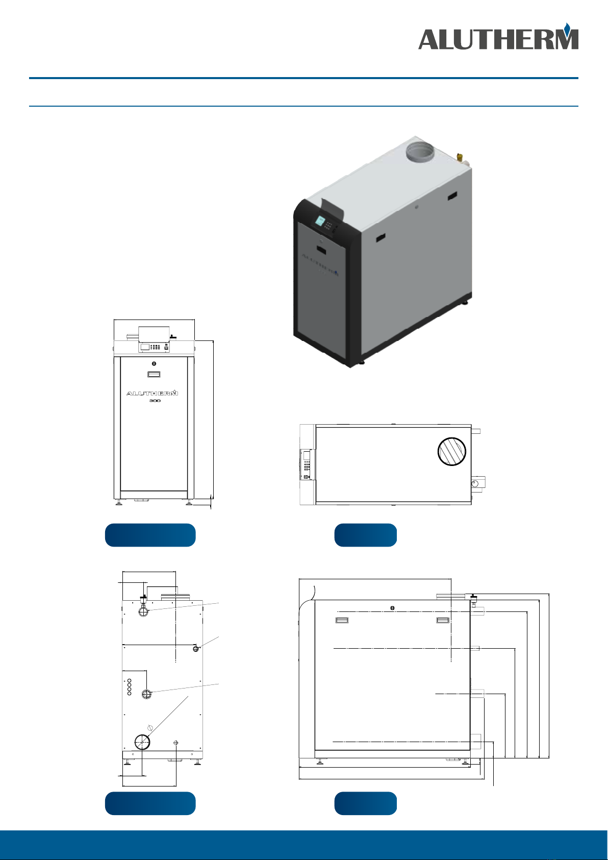
Sizes of casing
Width 600 600 600 600 mm
Depth 1281 1281 1281 1281 mm
Height 1226 1226 1226 1226 mm
Electrical
Protection 00B 00B 00B 00B IP
Electrical voltage/frequency 230/50 230/50 230/50 230/50 V/Hz
Standby power consumption* 5 5 5 5 W
Maximum power consumption* 1150 1150 1150 1150 W
Fuse 5 5 5 5 A
* as coming from factory without extra devices connected

ALUTHERM | Boilers 7ALUTERM A 170 - 300 | Installation, user and service manual | instructions for user
Heating
Alutherm A 170 - 300
2.1 COMPONENT MATRIX
COMPONENT MATRIX
PART A 170 A 210 A 260 A 300
Boiler control Honeywell Maxsys S4966V2052 S4966V2052 S4966V2052 S4966V2052
Display (user interface) DSP 49G2193 DSP 49G2193 DSP 49G2193 DSP 49G2193
Fan MVL 230 VAC G1G170-AB31-42 G1G170-AB31-42 G1G170-AB31-42 G1G170-AB31-42
Gas-valve Honeywell 230 VAC VR420VE5001-0000 VR425VE5022-0000 VR425VE5022-0000 VR425VE5022-0000
Venturi Honeywell VMU185 A1009 VMU300A1004 VMU335A1000 VMU335A1000
Texi Burner round 128 mm Worgas L=341 L=425 L=509 L=593
Silencer air-inlet yes yes yes no
Silencer flue-gas round 200 mm yes yes yes yes
NTC 12 k L=50 3 3 3 3
NTC 12 k OTC optional optional optional optional
Water low pressure sensor 1,6/0,8 bar (WPS) yes yes yes yes
Pressure difference switch 40 Pa in and 25 Pa out (APS) yes yes yes yes
Syphon pressure difference switch 8,3 mbar out (SPS) yes yes yes yes
Gas pressure switch : in 11,7-14,3 and out 8,6-11,4 mbar (GPS) yes yes yes yes

ALUTHERM | Boilers 8ALUTERM A 170 - 300 | Installation, user and service manual | instructions for user
Heating
Alutherm A 170 - 300
3 DIMENSIONS
Type A 170 - A 210 - A 260 - A 300
The appliance is not to be used by children or persons
with reduced physical, sensory or mental capabilities, or
lack of experience and knowledge. Children, even if being
supervised, must not play with the appliance.
In the case of failure or malfunction of the appliance, do not
attempt to repair it yourself. Please contact your installer.
Repairs must only be carried out by qualied technicians.
Failure to comply with these requirements can compromise
the safety of the appliance.
45 1181,50
600
148
400
181
548,50
157,50
397
110 (Air Inlet)
Flow R2"
Gas R1"
Return G2"
1134
45
124,50
482
1096
1181,50
1228
1281
1382
819
12
H
G
F
E
D
C
B
A
J
K
L
M
N
P
Q
R
A
B
C
D
E
F
G
H
J
K
L
M
N
P
Q
11
10
9
8
7
6
5
4
3
2
1
13
14
15
16
17
18
19
20
21
22
23
24
1
2
3
4
5
6
7
8
9
10
11
12
13
14
15
16
17
18
19
20
®
DE JA TE CH
FINISH:
DEBUR AND
BREAK SHARP
EDGES
UNLESS OTHERWISE SPECIFIED:
DIMENSIONS ARE IN MILLIMETERS
SURFACE FINISH:
TOLERANCES:
LINEAR: ± 0,2
ANGULAR: ± 0,5°
All rights reserved. This drawing is the property of Dejatech and
may not be copied or multiplied, neither whole nor partly.
It may not be submitted for perusal to third parties either.
Blauwwater 1
5951 DB Belfeld
T: 0031 77 4752270
www.dejatech.nl
Unit: mm
Projection:
PART NO.
CONFIDENTIAL
©
COPYRIGHT DEJATECH
DRAWN BY
APPROVED BY
NAME
DATE
MATERIAL:
REVISION
TITLE:
SCALE:1:10
SHEET 1 OF 1
A0
WEIGHT:
FF8L voor manual 03-02-2020
SIDEBACK
45 1181,50
600
148
400
181
548,50
157,50
397
110 (Air Inlet)
Flow R2"
Gas R1"
Return G2"
1134
45
124,50
482
1096
1181,50
1228
1281
1382
819
12
H
G
F
E
D
C
B
A
J
K
L
M
N
P
Q
R
A
B
C
D
E
F
G
H
J
K
L
M
N
P
Q
11
10
9
8
7
6
5
4
3
2
1
13
14
15
16
17
18
19
20
21
22
23
24
1
2
3
4
5
6
7
8
9
10
11
12
13
14
15
16
17
18
19
20
®
DE JA TE CH
FINISH:
DEBUR AND
BREAK SHARP
EDGES
UNLESS OTHERWISE SPECIFIED:
DIMENSIONS ARE IN MILLIMETERS
SURFACE FINISH:
TOLERANCES:
LINEAR: ± 0,2
ANGULAR: ± 0,5°
All rights reserved. This drawing is the property of Dejatech and
may not be copied or multiplied, neither whole nor partly.
It may not be submitted for perusal to third parties either.
Blauwwater 1
5951 DB Belfeld
T: 0031 77 4752270
www.dejatech.nl
Unit: mm
Projection:
PART NO.
CONFIDENTIAL
©
COPYRIGHT DEJATECH
DRAWN BY
APPROVED BY
NAME
DATE
MATERIAL:
REVISION
TITLE:
SCALE:1:10
SHEET 1 OF 1
A0
WEIGHT:
FF8L voor manual 03-02-2020
TOP
45 1181,50
600
148
400
181
548,50
157,50
397
110 (Air Inlet)
Flow R2"
Gas R1"
Return G2"
1134
45
124,50
482
1096
1181,50
1228
1281
1382
819
12
H
G
F
E
D
C
B
A
J
K
L
M
N
P
Q
R
A
B
C
D
E
F
G
H
J
K
L
M
N
P
Q
11
10
9
8
7
6
5
4
3
2
1
13
14
15
16
17
18
19
20
21
22
23
24
1
2
3
4
5
6
7
8
9
10
11
12
13
14
15
16
17
18
19
20
®
DE JA TE CH
FINISH:
DEBUR AND
BREAK SHARP
EDGES
UNLESS OTHERWISE SPECIFIED:
DIMENSIONS ARE IN MILLIMETERS
SURFACE FINISH:
TOLERANCES:
LINEAR: ± 0,2
ANGULAR: ± 0,5°
All rights reserved. This drawing is the property of Dejatech and
may not be copied or multiplied, neither whole nor partly.
It may not be submitted for perusal to third parties either.
Blauwwater 1
5951 DB Belfeld
T: 0031 77 4752270
www.dejatech.nl
Unit: mm
Projection:
PART NO.
CONFIDENTIAL
©
COPYRIGHT DEJATECH
DRAWN BY
APPROVED BY
NAME
DATE
MATERIAL:
REVISION
TITLE:
SCALE:1:10
SHEET 1 OF 1
A0
WEIGHT:
FF8L voor manual 03-02-2020
FRONT

ALUTHERM | Boilers 9ALUTERM A 170 - 300 | Installation, user and service manual | instructions for user
Heating
Alutherm A 170 - 300
In the case of failure or malfunction of the appliance, do not attempt to repair it yourself. Please contact your installer. Repairs must
only be carried out by qualied technicians. Failure to comply with these requirements can compromise the safety of the appliance.
4 OPERATION
4.1 General
The Alutherm A170-300 is a oor standing boiler, equipped with a cast aluminium heatexchanger. During heat demand the controller activates the
pump. The controller checks the air pressure switch (zero check) and increases the fan speed to perform an airow-check. Once the air pressure
switch closes the fan speed increases to ignition speed and a 5 second pre-purge is performed. The water pressure sensor, gas pressure switch and
siphon pressure switch are checked. When all pressure switches are closed and the water pressure is ok, the ignition is started.
The air needed for combustion is taken in from the outside (if room sealed) or the boiler house (type B ue installation) by the fan. The air is transported
through a gas/air mixing device creating a negative pressure. This negative pressure is an indication of the amount of air being transported. The
negative pressure is supplied to the gas-valve by an internal tube. The gas valve automatically adjusts the amount of gas that will be injected into
the venturi and that will be mixed with the air-ow. This mixture is supplied to the burner.
Ignition and ame-control of the mixture is done by two electrodes mounted on the burner hood.
Temperature control and safeguarding is done using 2 NTC’s. The boiler monitors the sensors continuously in order to control operation and ensure
safe operation.
4.2 Central Heating (CH)
4.2.1 On-o room thermostat
As standard the boiler is programmed for using an on-o room thermostat. The room thermostat has to be connected to the pin nrs. 1 + 2 on the
terminal strip. Open Therm will be recognized if connected on 1 + 2. The desired ow temperature is adjustable, but as standard is set to 85 °C.
At CH heat request from the room thermostat (and no DHW heat request present) the CH-pump is activated after 10 seconds. The controller will
adjust the burner-input in such a way that a ow-temperature of 85 °C towards the CH-circuit is achieved.
Warning: do not supply any voltage to these terminals as you may damage the controller
4.2.2 Optional 0-10V
The boiler may be controlled using a 0-10 V DC signal. Connect the negative (0V DC) to No. 3, and the positive (0-10V DC) to No.4 on terminal strip C2.
A loop of wire must be placed between the pin nrs. 1 and 2 of terminal strip C2. In the technician menu, enable 0-10V in the advanced CH settings
menu by setting, CH request to either 0-10V DC % or 0-10V DC SP.
4.2.2.1 0-10V DC % power control
A value between 2 and 10V DC generates a CH power demand proportional to this value between 0 and 100% (0% = minimum load, 100% = nominal
load). The heat demand is removed when the control signal falls below 1 volt. The setpoint of maximum ow temperature is set to 90°C.
In the user/technician menu, under diagnostics, boiler information the actual voltage input and target power are displayed.
4.2.2.2 0-10V DC Setpoint
A value between 2 and 10V DC generates a CH setpoint demand proportional to this value between CH minimum ow temperature and maximum
CH ow temperature. The heat demand is removed when the control signal falls below 1 volt. The minimum and maximum CH ow temperature can
be set in the technician menu, advanced CH settings, CH temperatures.
Technician menu----> 1 advanced settings----> 2 CH temperatures----> 1 absolute max. temperature
Setting higher than 90 degrees is not allowed
In the user/technician menu, under diagnostics, boiler information the actual voltage input and boiler setpoint are displayed.
Caution: Ensure that the 0-10V DC signal is free from electrical interference!

ALUTHERM | Boilers 10ALUTERM A 170 - 300 | Installation, user and service manual | instructions for user
Heating
Alutherm A 170 - 300
4.2.3 Outside Temperature Control OTC (optional)
The boiler may use an outdoor sensor to provide weather compensation (OTC). To activate weather compensation, connect an outdoor sensor to
numbers 5 and 6 on the terminal strip C2. Pin numbers 1 and 2 have to be bridged by a wire. Alternatively, those pin numbers (1 and 2) can be used
for connecting room thermostat on/o. In the technician menu, under advanced CH settings, CH request, OTC only must be selected. The outdoor
sensor is then automatically detected by the controller. The parameters corresponding with A-E in the gure below can be set in the technician
menu (advanced CH settings).
A OTC oset: minimum CH setpoint value
B OTC setpoint maximum: maximum CH setpoint value
C OTC weather cold: external temperature value at which the maximum CH value will be used.
D OTC weather warm: external temperature value at which the minimum CH value will be used
E OTC warm weather shutdown: external temperature value at which the CH demand will end
In the user menu an eco-setpoint reduction (night reduction) can be set. Day, week and weekend options are also be available (on, eco, o)
The outdoor sensor is available as an optional accessory.
The sensor should be installed on the north-side of the building at a height of approximately 2 meters.
Note: The resistance of the outdoor NTC should be 12 kOhm at 25 °C. Also see table of resistance for NTC’s at 6.6.2
4.2.4 Optional digital communication
The boiler supports digital communication with room thermostats using Open-Therm communication protocols (automatically recognised if
connected to pins 1 + 2 on terminal strip C2, also see 4.2.1.
CH Setpoint
Ext Temp
B
A
E D C

ALUTHERM | Boilers 11ALUTERM A 170 - 300 | Installation, user and service manual | instructions for user
Heating
Alutherm A 170 - 300
4.2.5 Slow start
The boiler uses a “slow start” procedure to prevent the boiler from supplying excessive power in low load situations.
After “zero check” APS and closure APS with pre purge ignition starts. Following a stabilization period, the boiler modulates down to low capacity
and maintains this capacity for 1 minute. Subsequently the boiler power increases at a rate of 4 °C/min until maximum capacity or set temperature
has been reached. Once heat demand has nished the burner will turn o following a set post purge period.
The graph below illustrates this;
4.2.6 Protection against insucient ow through boiler
If the requirements of 6.3.2 are fullled the boiler will protect itself against insucient ow. This is done by checking the dierence in temperature
between ow and return (so called ΔT).
In a low ow scenario the ΔT will rise rapidly. The ΔT safe-guarding principle is as follows;
At ΔT > 22 the boiler starts modulating
At ΔT between 22 and 27 the boiler continues modulating
At ΔT > 27 boiler the fan speed will reduce until ΔT < 25
5000
4000
3000
2000
1000
0
Fanspeed rpm
APS
Pre purge
Pre ignition Ignition
Slope 4°C/min
High
Post purge
O
Low
Time
Zero check APS
End o heat demand
Slow start sequence
Start heat demand

ALUTHERM | Boilers 12ALUTERM A 170 - 300 | Installation, user and service manual | instructions for user
Heating
Alutherm A 170 - 300
4.3 Domestic Hot Water (DHW)
4.3.1 External storage tank with thermostat (electric 3-way valve)*
As standard the DHW conguration is factory pre-set for an external storage tank + tank thermostat.
For hydraulic connection of an external storage tank to the boiler via an electric 3-way valve one should either use:
- the default conguration 2 pumps: 230 VAC DHW pump (terminal strip C1:
6,7,8) and CH pump (terminal strip C1: 9,10,11)
- an electric 3-way valve with a maximum travel time of 255 sec. (terminal strip C1: 6,7,8,9). At the end of the travel time in either direction DHW or
CH the 230 VAC on the 3-way valve will be switched o.
The 2 wires of the tank thermostat must be connected to numbers 7 and 8 on terminal strip C2.
In the case of using an electric 3-way valve adjust the setting in the technician menu, system settings, boiler parameters, number of pumps to: pump
and 3-way valve.
The 3-way valve travel time can be changed in the technician menu, system setting, boiler parameters, 3-way valve travel time.
4.3.2 External storage tank with NTC sensor
In case the storage tank is equipped with an NTC sensor, adjust the setting in technician menu, advanced DHW settings, DHW request to sensor.
Note: The resistance of the NTC sensor must have a value of 12 kOhm at 25 °C. The 2 wires of the tank NTC sensor must be connected to numbers 7
and 8 on terminal strip C2.
The set point temperature of the storage tank is adjustable (default set at 60°C, the ow temperature is DHW setpoint + 20K). Warning: if a CH heat
demand exists immediately after nishing the heat request for DHW, it is possible for high temperatures to ow into the CH system regardless of CH
set point (hot shot).
4.3.3 DHW priority/General behaviour with external storage tank
Disabling hot water operation: press Summer-Winter button R2-C4 (not active in main screen). See later in manual for further explanation.
Enabling hot water operation: press Summer-Winter button R2-C4(active in main screen). See later in manual for further explanation.
In the default boiler conguration, (2 pumps-DHW and CH pump), a DHW request has priority over CH request
In the technician menu, advanced DHW settings, DHW priority, the DHW priority over CH can either be disabled or a maximum DHW priority time
may be set.
In the case where the DHW priority is disabled and both demands are active at the same, both pumps (CH and DHW) will be activated. During this
time the ow temperature is set to either 80 °C (tank thermostat) or DHW setpoint + 20K (NTC sensor).
Notice: At outputs ≥ 40 kW double separation between exchanging media is required.
4.4 Cascade
For cascade application see appendix “cascade”

ALUTHERM | Boilers 13ALUTERM A 170 - 300 | Installation, user and service manual | instructions for user
Heating
Alutherm A 170 - 300
5 BOILER CONTROL
5.1 Control Panel
The control panel has 12 buttons and a display as shown in the gure below.
5.2 Push buttons on control panel
Description of push button use

ALUTHERM | Boilers 14ALUTERM A 170 - 300 | Installation, user and service manual | instructions for user
Heating
Alutherm A 170 - 300
5.3 User menu
By pressing the “menu-button” the display will show the text as given in the gure below.
By pressing the button marked “3” in the gure above
the user menu is accessed. Pressing the button marked
“5” returns back to the main screen.
By pressing the button marked “4” the installer menu
is accessed.
In the user menu the following options will be shown :
1. HEATING
2. DOMESTIC HOT WATER
3. HOLIDAY
4. MAINTENANCE
5. SETTINGS
6. CHIMNEY-SWEEPER
7. DIAGNOSTICS
By pressing up and down (R1-C2 and R3-C2) one of the
six options as shown above will highlight the desired
parameter. By pressing the OK button (R2-C2) the
chosen option will be selected.
Once an option has been slected it is possible to change
the parameters corresponding with the chosen option
5.3.1 Parameter/value setting
Pressing the up and down (R1-C2 and R3-C2) buttons
will highlight the desired parameter. Pressing the OK
button (R2-C2) will allow the chosen parameter to be
modied. This is shown below.
The actual value can be changed by pressing the R1-C1 and R2-C1 buttons. The changed value can be conrmed by pressing the OK (R2-C2) button
Pressing the back (R3-C1) button leaves the actual displayed parameter. If there are more parameters shown in the parameter value area (4) the
desired parameter can be selected by pressing the up and down ((R1-C2 and R3-C2) buttons.
5.3.2 Parameters accessible by user
An overview of the parameters accessible by the user is given on the next pages

ALUTHERM | Boilers 15ALUTERM A 170 - 300 | Installation, user and service manual | instructions for user
Heating
Alutherm A 170 - 300
1 Heating Heating user settings
1 CH temperature /OTC set Set the CH temperature and OTC curves parameters
1 CH setpoint Adjust setpoint of CH circuit
2 Outside tempera -
ture for CH o
Set the external temperature at which Heat demand is removed . If set OFF,
heat demand will never be removed.by controller (Only by removing RT or
bridge between terminal strip C2:1,2)
2 ECO setpoint reduction Set the temperature that will be subtracted from the actual setpoint when
ECO mode is activated
3 Scheduler set Invoke scheduler menu
1 Enable/disable on
board scheduler Based on selection is possible to enable/disable on board scheduler
Enable Enable on board scheduler
Disable Disable on board scheduler
2 Scheduler set Select to set scheduler
1 Monday
2 Tuesday
3 Wednesday
4 Thursday
5 Friday
6 Saturday
7 Sunday
8 Monday – Friday
9 Monday – Sunday
10 Saturday - Sunday
Used to program on board scheduler (On, O , Eco)
2 Domestic hot water Domestic hot water user settings
1 DHW set point Set the DHW temperature (in case of a DHW with sensor this is the actual
DHW temperature, in case of DHW with thermostat this is the base boiler ow
temperature)
2 ECO set point reduction Set the temperature that that will be subtracted from the actual setpoint
when ECO mode is activated
3 Scheduler set Invoke scheduler menu
1 Enable/disable on
board scheduler Based on selection possible to enable/disable DHW on board scheduler
Enable Enable on board scheduler
Disable Disable on board scheduler
2 Scheduler set Select to set scheduler
1 Monday
2 Tuesday
3 Wednesday
4 Thursday
5 Friday
6 Saturday
7 Sunday
8 Monday – Friday
9 Monday – Sunday
10 Saturday - Sunday
Used to program on board scheduler (On, O, Eco)

ALUTHERM | Boilers 16ALUTERM A 170 - 300 | Installation, user and service manual | instructions for user
Heating
Alutherm A 170 - 300
3 Holiday Holiday temperatures settings
1 CH holiday set point Set CH temperature used when Holiday mode active
2 DHW holiday set point Set DHW temperature used during holiday mode
4 Maintenance Set maintenance related info
1 Service information Used to display service company phone number or
entered info
2 Service due date Show next service due date . When date expire a MSG
is shown on lower part of main screen asking for service
5 Settings Boiler option settings
1 Select Language Allow selection of a dierent language
English Select for English
Italian Select for Italian
German Select for German
Russian Select for Russian
2 Select units Allow selection of dierent unit
Fahrenheit Select for Fahrenheit
Celsius Select for Celsius
3 Set date Allow RTC date setting
4 Set time Allow RTC time set. When selected a screen asking for
time format 24/12 Hours is opened. When selected ap-
propriate format screens jump to time entering screen
24 hours Select for 24 hours clock
12 hours Select for 12 hours clock
5 Restore factory data Pressing OK all the user settings will be restored to the
original factory default settings. See 1)
6 Chimney sweeper Manual mode. Hitting OK will force boiler to operate at
% of power
Timeout 15 minutes. While test in progress navigating
through other menus is allowed.
7 Diagnostics Will display boiler usage information and errors
1 Boiler information Boiler information
"1 CH request
2 DHW demand
3 Firing rate
4 Flame ionization
current
5 Boiler set point
6 Boiler supply tempera-
ture
7 Return temperature
8 Flue temperature
9 Outdoor temperature
10 DHW storage temperature
11 Boiler fan speed
12 CH ignitions
13 CH runtime
14 DHW ignitions
15 DHW runtime
16 System pressure
17 Heat Exchanger Temp.
18 0-10V input
19 Target power"
Will display the information shown in SUBMENU 2
When the line has a * at the end of the line means that
hitting OK when the line is highlighted will open a graph
that shows the latest 120 variable values stored every
12 minutes (24 hour history)

ALUTHERM | Boilers 17ALUTERM A 170 - 300 | Installation, user and service manual | instructions for user
Heating
Alutherm A 170 - 300
5.4 Installer (technician) menu
If the button marked “4” (page 21) is pressed the screen as
given in the gure below will appear.
Once the menu is accessed by entering the code the
following options will be shown
1. ADVANCED CH SETTINGS
2. ADVANCED DHW SETTINGS
3. SYSTEM SETTINGS
4. DIAGNOSTICS
5. USER SETTINGS
6. CASCADE
7. RESTORE FACTORY SETTINGS
Pressing the up and down (R1-C2 and R3-C2) buttons will
highlight the desired parameter group. Pressing the OK
button (R2-C2) selects the chosen parameter group.
Pressing the up and down (R1-C2 and R3-C2) buttons
will highlight the desired parameter subgroup. Pressing
the OK button (R2-C2) selects the chosen parameter
subgroup.
Once a parameter subgroup option has been chosen it
is possible to change the parameters corresponding with
the selected subgroup.
Follow the instructions as per 5.3.1 to set or change a
parameter.
5.4.1 Parameters accessible by installer (technician)
An overview of the parameters accessible by the installer (technician) is given on the following pages.

ALUTHERM | Boilers 18ALUTERM A 170 - 300 | Installation, user and service manual | instructions for user
Heating
Alutherm A 170 - 300
Lockout history Show a list of recent errors. Hitting OK on the highlighted error will open
screens that contain details on boiler status when error occurred
1 Advanced CH settings Heating installer advanced settings
1 CH power set Set power of boiler in CH mode
1 Maximum power Set % of boiler maximum power in CH mode
2 Minimum power Set % of boiler minimum power in CH mode
2 CH temperatures Set (selecting OK) and show CH temperatures
1 Absolute max temp Set CH absolute max temperature (CH temperature boiler settings will never
exceed).
2 CH maximum set point Determine higher boundary of CH setpoint
3 CH minimum set point Determine lower boundary of CH setpoint
4 CH set point hysteresis Set CH setpoint hysteresis (temperature above setpoint at which boiler will
be switched o)
3 OTC parameters Set the OTC parameters
1 Outside temp for max CH
2 Outside temp for min CH
3 Outside temp for CH o Set the external temperature at which Heat demand is removed . If set OFF
heat demand will never be removed.by controller (Only by removing RT or
bridge between terminal strip C2:1,2)
4 OTC set point table Show in a table the link between external temperature and actual setpoint
determined by the OTC parameter selection
5 OTC curve Show in a curve the link between external temperature and actual setpoint
determined by the OTC parameter selection
4 CH pump settings Set pump usage related parameters
1 post pump time Set the CH pump overrun time.
5 CH anti cycling
timer Set the ant cycling timer (minimum time between boiler goes o till next
ignition)
6 CH request type Allow selection of dierent CH requests:
Only OTC Select OTC: outdoor Temperature controller 3)
Room Tstat Select RT/OT: Room Thermostat or OpenTherm
0-10V Signal [%] Select 0-10Vdc input for Power mode 3)
0-10V Signal[SP] Select 0-10Vdc input for setpoint mode 3)
2 Advanced DHW settings Domestic hot water advanced settings
1 DHW power Set power of boiler in DHW mode
1 Maximum power Set % of boiler maximum power in DHW mode
2 Minimum power Set % of boiler minimum power in DHW mode
2 DHW temperatures Set (selecting OK) and show DHW temperatures
1 Storage temperature set
point Set Flow temperature during DHW mode when DHW done via a thermostat
(Switch)
2 Boiler temperature set
point Set DHW temperature setpoint when DHW done with temperature sensor

ALUTHERM | Boilers 19ALUTERM A 170 - 300 | Installation, user and service manual | instructions for user
Heating
Alutherm A 170 - 300
3 DHW pump settings
DHW post pump time
4 DHW priority
1 DHW priority status Enable /disable DHW priority over CH
Enabled Enable
Disabled Disable
2 DHW priority timeout present for the same amount of time).
O Select for no timeout (While DHW priority status is enabled)
1..60 minutes Set timeout in minutes. (While DHW priority status is enabled)
5 DHW request type
Switch DHW start when DHW thermostat closes
Sensor DHW start based on required vs actual DHW temperature
3 System setting Boiler and system parameters
1 Boiler parameters Boiler related parameters
1 Ignition power Set power % used when igniting burner.
2 Delay siphon check Delay time to validate a syphon error
3 Number of boiler pump
Pump and
3WayValve System with pump and 3-way valve
Two pumps System with 2 pumps
4 Pump speed max Maximum % of PWM pump speed
5 Pump speed min Minimum % of PWM pump speed
6 Antilegionella Based on selection possible to enable/disable Antilegionella protection
Enabled Enable Antilegionella protection
Disabled Disable Antilegionella protection
7 Modbus parameters Set Modbus parameters
Address Set address default: 1
Baudrate Set baudrate default: 38400 bps
Frame Set frame 8N!
8 3 Way valve travel time Select for setting travel time 3WV in seconds
2 User interface settings
1 Select language Allow selection of a dierent language
English Select for English
Italian Select for Italian
German Select for German
Russian Select for Russian

ALUTHERM | Boilers 20ALUTERM A 170 - 300 | Installation, user and service manual | instructions for user
Heating
Alutherm A 170 - 300
2 Select unites Allow selection of dierent unit
Fahrenheit Select for Fahrenheit
Celsius Select for English
3 Set date Set system date
4 Set time Set system time
3 Service settings Service information
1 Service information Used to insert service company phone number (selection
done as per technician password enter)
2 service due date Next service due date (input done as per date entering)
4 Diagnostics Boiler information and lockout history
1 Boiler information Boiler information
"1 CH request
2 DHW demand
3 Firing rate
4 Flame ionization current
5 Boiler set point
6 Boiler supply temperature
7 Return temperature
8 Flue temperature
9 Outdoor temperature
10 DHW storage temperature
11 Boiler fan speed
12 CH ignitions
13 CH runtime
14 DHW ignitions
15 DHW runtime
16 System pressure
17 Heat Exchanger Temp.
18 0-10V input
19 Target power"
Will display the information shown in SUBMENU 2
When the line has a * at the end of the line means that
hitting OK when the line is highlighted will open a graph
that shows the latest 120 variable values stored every 12
minutes (24 hour history)
2 Lockout history Shows the list of recent errors. Hitting OK on the high-
lighted error will open new screen that contains details of
the boiler status when the error occurred.
3 Manuel test See chimney sweeper.
5 User settings Access the user settings from the advanced menu.
1 Heating Heating user settings
1 CH temperature/ OTC set Set the CH temperature and OTC curves parameters
1 CH set point Adjust setpoint of CH circuit
2 Outside
temperature
for CH o
Set the external temperature at which Heat demand is
removed .
2 ECO set point reduction Set the temperature that will be subtracted from the actual
setpoint when ECO mode is activated
3 Scheduler set Invoke scheduler menu
1 Enable/dis -
able on board
scheduler
Based on selection is possible to enable/disable on board
scheduler
Enable Enable on board scheduler
Disable Disable on board scheduler
This manual suits for next models
3
Table of contents
Popular Heater manuals by other brands

Hatco
Hatco Glo-Ray GRAM Series Installation and operating manual

Uberhaus
Uberhaus 10625001 Operator's manual

Dimplex
Dimplex DESC2TN Installation and operating instructions

Pelonis
Pelonis PHTA8AWB owner's manual

DeLonghi
DeLonghi CERAMIC FAN HEATER instructions

LVI
LVI YALI PARADA Installation and operating manual