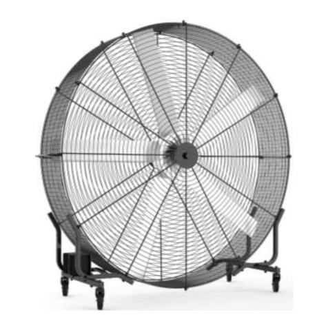
Ama Tech AH-5 User manual


1
Installation Guide
Type/Model to be installed:
Helicopter Fan AH-5
Helicopter Fan AH-6
Helicopter Fan AH-7

2
Contents
Important Safety Instruction: Please read and save this instruction.......................................... 3
Specifications of Helicopter Fan ............................................................................................... 5
Pre-Installation Components Inspection (1).............................................................................. 6
Pre-Installation Components Inspection(2)............................................................................... 7
Pre-Installation Components Inspection (3).............................................................................. 8
Pre-Installation Components Inspection (4).............................................................................. 9
Required Tools:......................................................................................................................... 9
(1) Installation Structure: I-Beam (Standard).......................................................................... 10
(1) Installation Structure: Square Steel Beam (Optional)........................................................ 11
(1) Installation Structure: Cement Beam (Optional) ............................................................... 12
(1) Installation Structure: Round Steel Beam (Optional)........................................................ 13
(2) Installing Main Machine: Extension, Fan Unit.................................................................. 14
(3) Installing Fan Blades: Installation of Fan Blades.............................................................. 15
(4) Installing Cables: Connect to Main Machine, Lay out Control System Circuit ................ 16
(5) Installing Control System: Preparation, Installation and Test ........................................... 17
(6) Arranging the site environment: Clean Environment........................................................ 20
Service Conditions of Equipment............................................................................................ 20
Operation Instruction............................................................................................................... 21
Warranty and Maintenance Terms of New Product................................................................ 22

3
Important Safety Instruction: Please read and save this
instruction
For reducing the risk of fire, electric shock or personal injury, please abide by the following points:
ATTENTION: Installation and wire connection must be operated by qualified personnel in accordance
with all proper regulations and standards.
ATTENTION: When cutting or drilling ceiling, please do not damage wire and other hidden water piping
and circuits of appliance.
ATTENTION: Only use this unit by the method instructed by manufacture. If there is any problem, please
contact manufacture.
WARNING: Before repairing and cleaning unit, please turn off the power of repair panel, and lock the repair cut-off
device, in order to prevent accidental power-on. If the repair cut-off device cannot be locked, please fix
obvious warning sign (such as label) on repair panel.
ATTENTION: Installation of brushless big fan must be in accordance with requirements specified by this Installation
Guide and abide by requirements of National Electrical Code (NEC) and all local regulations. Finally,
guaranteeing compliance is your responsibility. Not abiding by relevant regulations may cause
personal injury or property loss.
ATTENTION: When fan is powered on, please be cautious to use common sense. Please do not connect fan to
damaged or dangerous power supply. Please do not try to solve circuit problem or trouble by yourself.
If you have any problem about installation of this fan, please contact AmaTech.
WARNING: For reducing risk of fire, electrical shock or personal injury, brushless big fan must be installed with
controller (proper model is marked on package box) provided by helicopter fan simultaneously. Other
components cannot be replaced.
ATTENTION: When overhauling or changing fan components, a safety equipment needs to be dismantled or cut, this
safety equipment must be re-installed or returned to original position.
WARNING: During cleaning and repairing of tester, there could be risk of fire, electrical shock or personal injury!
Please turn off fan power before repairing.
ATTENTION: When installing, adjusting or repairing, please do not bend fan blades. Please do not insert any foreign
substances when fan blades are rotating.
WARNING: When installing fan, please stay alert and use common sense. When influence of fatigue or drug, alcohol
or medicine does not subside, please do not install fan. Any carelessness during installing fan may cause
serious personal injury.
ATTENTION: When installing this fan, some electrical tools require to be used. Please abide by safety regulations in
operation manual of every tool. Do not use tools for other purpose without manufacture’s instruction.
ATTENTION: Warranty of brushless big fan does not cover equipment damage or trouble caused by incorrect

4
installation.
ATTENTION: When fan is installed on GFCI (Ground Fault Circuit Interrupter) protective branch circuit, the fan
can be used under humid environment.
WARNING: This circuit is not suitable for persons (including children) with reduced physical, sensory or mental
capabilities or lack of relevant experience and knowledge, unless they have been given supervision or
instruction concerning use of the appliance in a safe way by those who are responsible for their safety.
Children should be supervised, in order to ensure they cannot play with appliance.
Please ATTENTION: If the fan is installed in the USA, installation must abide by the following guidance of National
Fire Protection Association (NFPA):
⚫Fan must be located in the center of four (4) adjacent fire sprinklers.
⚫The vertical distance between fan and flow deflector of fire sprinkler should be no less than 3
ft (91.4 cm).
⚫Fan must be interlocked, it can immediately be turned off when receiving water flow signal
of alarm system.
WARNING: If fan abnormally swings, please immediately stop using overhead fan and contact manufacture,
maintenance agent or qualified personnel.
WARNING: Components of safety hanging system device should be replaced by manufacture, maintenance agent or
qualified personnel.
Installation of hanging system should be operated by authorized agent of brushless fan and corresponding qualified
personnel.
It is not suitable to be used in salt fog environment.
When finish installation, please leave this installation guide to fan user.

5
Specifications of Helicopter Fan
Fan Specifications:
Specifications Parameters
Model
AH-7
AH-6
AH-5
Fan Diameter (M)
7.15
6.15
5.15
Min/Max Speed (RPM)
25/55
25/60
25/75
Load Current (A)
0.5/3.8A
0.46/2.8A
0.43/2.0A
3-Phase Voltage (V)
220
220
220
Max Affected Area (m
2
)
1300
1000
700
Wind Volume at Max
Speed (m
3
/min)
14900
12400
10900
Noise Level (dB)
<40
<40
<40
Fan Blade
5
5
5
Weight of Fan Unit (kg)
69
60
54
*Output voltage cannot exceed input voltage (not including 120V model). Output power of all controllers is
3Φ, which is not related to input power

6
Pre-Installation Components Inspection (1)
Inspect Components:
ATTENTION: Before hanging fan, please do not dismantle protection package of fan unit.
ATTENTION: If you ordered multiple fans, please ensure that the all components of every fan are put together!
The following diagram is not zoomed in/out according to scale. All boxes should have stickers, in order to show the
packed contents.
Fan is packed into four (4) boxes when sending, which are:
1. Main Box: Fan Unit*1
2. Fan Blades Box: Fan Blade*5
3. Other Components Box: Mounting Clamp 2, Universal Mount*1, Extension*1, Guy Wire Plate*2, Lamp Holder
Plate*1, Lamp Holder*1, Airfoil*5, Galvanized Hex Bolt-M12*60 (4 pieces), Galvanized Hex Bolt-M12*100 (2
pieces), Galvanized Hex Socket Head Bolt-M12*100 (2 pieces), Galvanized Hex Socket Head Bolt-M12*110 (2
pieces), Nylok Galvanized Hex Bolt-M12*60 (10 pieces), Galvanized Spring Washer-M12 (20 pieces),
Galvanized Iron Washer M12 (30 pieces), Galvanized Nylon Hex Lock Nut-M12 (10 pieces), Self-tapping Screw
-4*20(10 pieces), Wire Rope Clamp (16 pieces), Turn Buckle (4 pieces)
4. Extension Units Box
1.Main Box*1
Fan Unit*1
2. Fan Blade*5
Fan Blade *5

7
Pre-Installation Components Inspection(2)
3.Other Components Box-1
Mounting Clamp*2
Universal Mount*1
Extension*1
Guy Wire Plate*2
Water-proof Cap*1
Winglet*5

8
Pre-Installation Components Inspection (3)
3.Other Components Box-2
Hex Bolt:
M12*60 (4 pieces);M12*100 (2 pieces)
Hex Socket Head Bolt
(M12):
M12*100 (2 pieces)
Hex Socket Head Bolt
(M12):
M12*110 (2 pieces)
Hex Bolt (Nylok):
M12*60 (10 pieces)
Self-tapping Screw
(M4):
M4*20 (10 pieces)
Nylon Hex Lock Nut:
M12 (10 pieces)
Turn Buckle: 3/8 (4 pieces)
Wire Rope Clamp:
3/16 (16 pieces)

9
Pre-Installation Components Inspection (4)
4. Controller Units Box
Total Weight: 45 kg (Gross Weight: Fan Unit + Components)
Required Tools:
Mechanical Installation
Appliance Installation
Standard and Metric Wrench Kit
Phillips Screwdriver and Flathead Screwdriver
Standard and Metric Screw and Ratchet Kit
10- 14 AWG Wire Stripper
Standard and Metric General Wrench Kit
Medium Pliers
60 NM Torque Wrench
Multimeter
Phillips Screwdriver and Flathead Screwdriver
Metric General Hex Socket Head Screw
Driller
Steel Saw
Level * 2
Tape Measure

10
(1) Installation Structure: I-Beam (Standard)
Required Components: Mounting Clamp*2, Universal Mount*1, Extension*1, Hex Bolt (M12*60*4 pieces), Hex Bolt
(M12*100*2 pieces), Nylon Hex Lock Nuts, Flat Washers, Spring Washers (Select according to site
specification)
Installing Steps: (1)Attach the Extension to the bottom of the Universal Mount, then pre-tighten the Hex Bolts (M12*100*2
pieces).
(2) After confirm installation position, position the Universal Mount under the I-Beam, assemble one
Mounting Clamp with one side of the I-Beam and then pre-tighten them. The above step will be repeated
on the other side. After finish, apply loctite to all bolts then tighten them all, torque to 60 NM. (overhead
operation).
Attention: Before overhead operation, the safety helmet, safety clothing, safety rope and others should be worn, and
equipment for climbing should be prepared, then all components to be installed need to be put in. When
overhead operating, the safety rope must be confirmed to be fixed.
Breakdown Drawing:
Installation Diagram:

11
(1) Installation Structure: Square Steel Beam (Optional)
Required Components: 2-Piece Type Mounting Clamp*1, Universal Mount*1, Extension*1, Threaded Rods, Flat Washers,
Spring Washers, Nylon Hex Lock Nuts. (Select according to site specification)
Installing Steps: (1) Attach the Extension to the bottom of the Universal Mount, then pre-tighten the Hex Socket Head Bolts
(M12*100*2 pieces).
(2) After confirm installation position, position the Universal Mount under the Square Steel Beam, assemble
the Mounting Clamp with low edge of the Square Steel Beam and then pre-tighten them, and pre-tighten
all Hex Nuts on the Threaded Rods. After finish, apply loctite to all bolts then tighten them all, torque to
60 NM. (overhead operation).
Attention: Before overhead operation, the safety helmet, safety clothing, safety rope and others should be worn, and
equipment for climbing should be prepared, then all components to be installed need to be put in. When
overhead operating, the safety rope must be confirmed to be fixed.
Breakdown Drawing:
Installation Diagram:

12
(1) Installation Structure: Cement Beam (Optional)
Required Components: L Type Bracket*2, Universal Mount*1, Extension*1, Expansion Bolts, Flat Washers, Spring Washers,
Nylon HexLock Nuts, Hex Bolts. (Select according to site specification)
Installing Steps: (1) Attach the Extension to the bottom of the Universal Mount, then pre-tighten the Hex Socket Head Bolts
(M12*100*2 pieces).
(2) After confirm installation position, attach the L Type Bracket to one side of Cement Beam and fix the L
Type Bracket on the Cement Beam with the Expansion Bolts, the above step will be repeated on the
other side of Cement Beam (bottoms of 2 L Type Bracket should be leveling). Position the Universal
Mount under 2 L Type Brackets with Hex Bolts pre-tighten. After finish, apply loctite to all bolts then
tighten them all, torque to 60 NM. (overhead operation).
Attention: Before overhead operation, the safety helmet, safety clothing, safety rope and others should be worn, and
equipment for climbing should be prepared, then all components to be installed need to be put in. When
overhead operating, the safety rope must be confirmed to be fixed.
Breakdown Drawing:
Installation Diagram:

13
(1) Installation Structure: Round Steel Beam (Optional)
Required Components: U Type Fixing Ring*3, Universal Mount*1, Extension*1, Flat Washers, Spring Washers,
Nylon HexLock Nuts. (Select according to site specification)
Installing Steps: (1) Attach the Extension to the bottom of the Universal Mount, then pre-tighten the Hex Socket Head Bolts
(M12*100*2 pieces).
(2) After confirming installation position, attach the Universal Mount under Round Steel Beam, put U Type
Fixing Rings on the Round Steel Beam and pre-tighten them. Pre-tighten all nuts. After finish, apply
loctite to all bolts then tighten them all, torque to 60 NM. (overhead operation).
Attention: Before overhead operation, the safety helmet, safety clothing, safety rope and others should be worn, and
equipment for climbing should be prepared, then all components to be installed need to be put in. When
overhead operating, the safety rope must be confirmed to be fixed.
Breakdown Drawing:
Installation Diagram:

14
(2) Installing Main Machine: Extension, Fan Unit
Required Components: Extension*1, Guy Wire Plate*2, Fan Unit*1, Hex Socket Head Bolt (M12*80*4 pieces),
(M8*16*4 pieces), Hex Nut(M12*10*4 pieces), Turn Buckle(3/8*4 pieces), Wire Rope
Clamp (3/16*18 pieces), I-Beam Clamp (4 pieces).
Installing Steps: (1) Position the Universal Mount under I-Beam, Square Steel Beam, Cement Beam and Round Steel Beam.
(Overhead operation)
(2) Position the Extension to bottom of the Universal Mount, put washers on both sides, insert Hex Socket Head Bolts and
tighten Hex Nuts. (Overhead operation)
(3) Insert the main axis of Fan Unit into the Extension, put the Guy Wire Plates on both sides, then attach
washers to outside of Guy Wire Plates, insert Hex Socket Head Bolts, tighten Hex Nuts to finish it, torque to
60 NM. (Overhead operation)
(4) Stretch cable hose, then thread black cable into hose, expose about 30cm cable, cut the rest cable for
backup, thread cable into the Extension from Light Base position, expose 30cm cable for connecting
circuit of Main Machine. (Overhead operation)
(5) Thread one end of the Turn Buckle through hole of the Guy Wire Plate, thread the other end through
safety Guy Wire and fix on the I-Beam, finally attach I-Beam clamp on the I-Beam. Use Level to
measure and adjust Safety Cable, after confirming Guy Wire Plate to keep straight, then tighten all bolts
to finish it. (Overhead operation)
(6) Apply loctite to every bolts. (Overhead operation)
(3)
(1)
(2)
(4)
Exposed End

15
(3) Installing Fan Blades: Installation of Fan Blades
Required Components: Fan Blade*5, winglet*5, Aluminum Mounting Clamp*5, Clamp Washer*5, Self-Tapping Screw
(M4*20*10 pieces)
Installing Steps: Tighten fan blades to airfoils with screws, torque to 3.5 NM, (A). Assemble them with fan unit by overhead
operation (B). Avoid scratching surfaces of fan blades when installing fan blades, apply loctite to all screws.
Attention: When installing one fan blade, the other person needs to support fan blade to prevent fan blade from
sliding, the rest fan blades need to be installed by diagonal way.
(A)
(B)

16
(4) Installing Cables: Connect to Main Machine, Lay out
Control System Circuit
Required Components: Cables, Cable Clamps, Electrical Tape, European Style Male/Female Terminals
Installing Steps: When stripping cable, do not cut the copper wire, connect European Style Male/Female Terminals based on
corresponding cable colors on the Main Machine. When laying out circuit, keep cables horizontal, vertical
and beautiful, the distance between Cable Clamps is 1.5m. (Overhead and ground operation)
Attention: Cables must be connected with same colors, for example, yellow green connect to yellow green, red connect
to red. Cables shall be covered by Electrical Tap and hidden in Main Machine, so as to prevent circuit from
phenomenon of short circuit or loose contact. (Or connect cable with junction box, optional)
Attention: Method of threading cables into Extension is shown as follow, remember to prevent circuit from contacting
screws.
Thread
from here
Thread
from here

17
(5) Installing Control System: Preparation, Installation and
Test
Required Components: Controller Box, Level, Electrical Driller, Multimeter
Installing Steps: (1) Use key to open control system, install assembled components, fix control system on the wall, use level
to measure levelness, mark the hole positions, use driller to make holes.
(2) Fix control system on the wall, cables shall be stripped and connected to control system, and connect
cables to control system according to corresponding circuit colors.
(3) Use Multimeter to measure after finish, turn on circuit breaker and power it on, turn on fan for test,
counterclockwise rotation direction is forward direction. Test fan for 15 minutes to observe whether the
sound of product is normal, confirm whether current is within rated range, and confirm the distance
between fan and obstruction when fan is running, in order to guarantee the safe distance when fan is
running (30cm to end of fan blade, 1m from left to right).
Attention: Reference the Instruction for connection methods under different circumstances.

18
✓Description
Description of Main Circuit Terminal
Connect to Working Frequency Power Supply
Connect to Motor
Connect to Braking Resistor (Built-in Braking Unit in B Frame )
Grounding Terminal
Notes: There are no built-in braking units in Frame A, and no “+/P” and “PR” terminals.
✓Main Circuit Terminal Array of Various Machines
Frame A
Frame B
✓Braking Resistor Connection
Notes: Braking resistor can be selected by built-in braking unit of corresponding variable frequency
drive of FrameA and B. Please reference Paragraph 3.3 for frame instruction.

19
Trouble Codes of Variable Frequency Drive:
Code
Displayed Content
on the Screen
Symptoms
Solution
ERROR
1. Power supply voltage is
low
2. Reset function RES“on”
3. Operator loose contact
with Main Machine
4. Trouble of internal circuit
5. CPU misoperation
1. Supply with normal power
2. Cut off reset switch
3. Confirm to connect operator to
Main Machine
4. Replace variable frequency
drive
5. Restart variable frequency drive
OC0
Over current during
stopping machine
Output current exceed 2 times
as rated current of variable
frequency drive
Variable frequency drive may be
interrupted, power off and re-power
on, if this abnormal alarm happens
repeatedly, please sent it to
manufacture for inspecting and
repairing
OC1
Over current during
acceleration
1. If there is rapid acceleration or
rapid deceleration, please
extend time of acceleration and
deceleration
2. Prevent load from rapidly
enlarging
3. Check whether short circuit will
happen on U/T1, V/T2 and
W/T3 terminals of motor
OC2
Over current during
constant speed
OC3
Over current during
deceleration
OV0
Over voltage
during stopping
machine
Voltage between terminal (+/P)
and (-/N) is over high
Check whether input power is
normal
OV1
Over voltage during
acceleration
1. If there is rapid acceleration or
rapid deceleration, please
extend time of acceleration and
deceleration
2. Check whether regenerative
braking resistor between
terminal +/P and PR will fall
3. Check whether the set value
between 06-05(P.30) and 06-06
(P.70) is correct
OV2
Over voltage during
constant speed
OV3
Over voltage
during deceleration
THT
IGBT module is
overheated
Thermal relay operation of
IGBT module
Prevent variable frequency drive
from long-time overload running
THN
Motor is
overheated
Electronic thermal relay
operation
1. Check whether set value of
06-00(P.9) is correct (based on
external motor)
2. Reduce load
OHT
Operation of
thermal relay of
external motor
Thermal relay operation of
external motor
1. Check whether external thermal
relay capacity match to motor
capacity
2. Reduce load
OPT
Peripheral
abnormality
1. Communication
abnormality, exceed retry
times of communication
abnormality
2. Communication
interruption, exceed
allowable time of
communication interval
1. Correctly set parameters related
to communication
This manual suits for next models
2
Table of contents
Other Ama Tech Fan manuals
Popular Fan manuals by other brands

Clarke
Clarke CDF20HV-P Operating & maintenance instructions

turbionaire
turbionaire MIO Series instruction manual

smaco
smaco F36AR Instructions for use

Black & Decker
Black & Decker BFSR16B instruction manual

Vornado
Vornado EXO51 HD owner's guide

Delta Electronics
Delta Electronics FFB0612DHE Dimensions and installation information

S&P
S&P TDM-200 User instruction

QuFresh
QuFresh QuF100X instructions

Broan
Broan 512 instructions

Mitsubishi Electric
Mitsubishi Electric EF-20UYS-UL Installation instructions manual

MALTEC
MALTEC WBS60Wt Operation and maintenance manual

Mitsubishi Electric
Mitsubishi Electric Lossnay LGH-150RVXT-E operating instructions