AMALGAMATED INSTRUMENT RM6-IV Guide

RM6-IV
DIN Rail Mount
DC Current/DC Voltage
Process Monitor
Operation and Instruction Manual

Introduction
Thismanualcontainsinformationontheinstallationandoperationof
theRM6-IVmonitor.TheRM6-IVacceptsinputsintheranges0to20mA, 4
to20mA, 0 to100mV,0to1Volt,0 to 10 Volts, 0 to100Voltsoruserset
input (called the USER range) limits anywhere within the above ranges.
Selection of input range is via the INPt function. The SCLE function is
used to scale any of the standard input ranges whilst the USER input is
scaled using the CAL1 and CAL2 “live” input functions.
The displayed output may be scaled to read in any engineering
units. A square root extractor is included and can be configured as
required.Twoalarm/control relaysareprovided,one ofwhich(relay2) may
be configured via a DIP switch to operate as a hardware failure alarm. The
4-20mA recorder output included is easily setup to retransmit between
scaled input values.
Unless otherwise specified at the time of order your RM6-IV has
been factory set to a standard configuration. This configuration can be
easily changed by the user. All changes to configuration are made via the
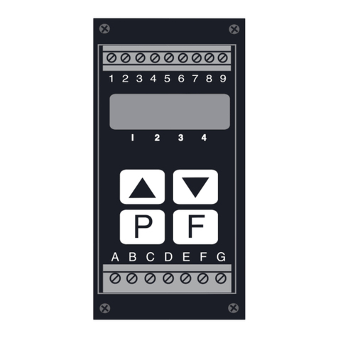
four push buttons ( P,F,^and v) located at the front of the unit.
The RM6 series instruments are designed for high reliability in
industrial applications. The LED display can be set for desired brightness
level to suit most locations and light levels.

Mechanical Installation
The dimensions of the RM6-IV are shown in the diagrams below.
The RM6 is designed for DIN rail, horizontal mounting. The instrument
snapsonto35mmDIN standardrails(EN50022).ToinstalltheRM6simply
clip onto the rail shown below. To remove lever the lowerarm downwards
as illustrated below. DIMENSIONS
REMOVING FROM
THE DIN RAIL
CLIPPING THE INSTRUMENT
ONTO THE DIN RAIL

Electrical Installation
The diagrams below show the electrical connection points for the
RM6-IV. As the instrument is designed for continuous use no power switch
is fitted. It is recommended that an external switch and fuse be provided to
allow the unit to be removed for servicing.
The terminal blocks are of the plug in type for ease of connection.
Wires of up to 1.5mm diameter (2.5mm dia. for power supply and relay
terminals) may be fitted. Connect the wires to the appropriate terminals as
indicated in the diagrams below. Ensure that all connections are correct
before switching on. When power is applied the instrument will cycle
throughadisplaysequence,seethe“SwitchingOnTheInstrument”section
for full details of display messages. At the end of the switch on display
sequencea“livereading”will be shown on thedisplayifaninputis present.
A test input or a known sensor input may be used at this stage to check the
operation of the instrument.

Examples of sensor connection.

DIP Switch & Link Settings
TheRM6hastwoDIPswitchesandasetofinputlinkslocatedonthe
main board. To dismantle the instrument and gain access to the switches
and links firstly remove the earth screw which passes through the side
panel of the aluminium case then remove the four screws which secure the
front display panel to the case and pull the display out of the case.
DIP Switch 1 - When set to the OFF position the instrument behaves
normally.Whensettothe ON position the instrument will block access
to any functions thus providing security for the existing setup. If an
attemptismadetoenterCALorfunctionsetupmodeswiththeswitchin
the ON position the message NO ACCS will flash indicating that the
access is blocked.
DIP Switch 2 - When set to the OFF position the instrument behaves
normally and there is access to alarm 1 and 2 functions. When set to
ON alarm 2 becomes a dedicated hardware failure alarm. Alarm 2 will
operate in the normally closed (energised) mode and will open
(de energise) if the entire instrument, its analog to digital converter or
its micro controller fails. In the ON position there will be no access to
alarm 2 functions since this alarm is now dedicated.
Input Links - Input links on the main board are used to select the
required input range, ensure that the link setting corresponds to the
software setting (see INPt function). To change a link setting simply
pullthetabconnectedtothelinktoremoveitfromtheunwantedsetting
and place the link or links in the required position. Note the 4-20mA /
0-20mA and 0-0.1V inputs each require two links.
Main Board

Switching On The Instrument
When the instrument has been electrically connected you can view
the status of the input range and measurement mode settings by applying
power and watching the display sequence. If you connect a sensor or test
voltage/current you will also see the reading obtained from the sensor or
test input. Upon applying power the display automatically scrolls through
five displays. The first lights up all LED digits i.e. displays eights. By
watching this display you can confirm that all display segments are
functioning. The second display is a factory identification message. The
third display gives the software revision number of the instrument. The
fourthdisplayshowstheinputrangeselected,seethe“FunctionsAvailable”
and “Setting Up The RM6-IV” chapters if this is not the range you require.
The fifth display shows the measuring mode being used, again see the
“FunctionsAvailable”and“SettingUpTheRM6-IV”sectionsfordetails.The
sixthdisplayshows the sensor/testinput reading,ifany input isconnected.
The switch on display sequence is illustrated in the diagram below.

Functions Available
Note: Some of the functions described in this chapter are available
only when the instrument is powered up in CAL mode. See “Setting Up the
RM6-IV”,page10,fordetailsofthismode.Someofthesefunctionsareonly
seen when USER input mode and some when in the standard voltage or
currentselectioninputmode.See the function tables and detailsin“Setting
Up the RM6-IV”.
Two measuring modes are available. These are:
Standard mode - This mode is indicated by Stnd on the display.
Use this mode for linear measurement applications.
Squarerootmode-ThismodeisindicatedbySqRt onthedisplay.
Use this mode when the square root facility is required in the measurement
being made.
These modes are chosen under the “Select” (SLCt) function. The
mode chosen determines how the sensor inputs (input (I NPt) function)
will be interpreted by the instrument. See “Setting Up The RM6-IV” chapter
for full details and set up procedure for each mode and function.
Brief Description of Functions:
Alarm/Control relay functions - Two Alarm/Control relays are
provided, each one can be adjusted to change the low setpoint (A1Lo and
A2Lo), the high setpoint (A1Hi and A2Hi), the hysteresis or deadband
(A1HY and A2HY), the trip time (A1tt and A2tt) additionally each can
be set to operate as normally open (A1n.o and A2n.o) or normally closed
(A1n.c and A2n.c). (Note: DIP Switch 2 is used to select alarm 2
operation, refer to page 5).
Retransmission output - The recorder output or analog
retransmissionoutputisset at4-20mA. ThefunctionsREC_ andREC~ set
the display values at which 4 and 20mA are transmitted respectively.
Digital filter (FLtr) - allows the user to alter the input filter level
from 0 to 8, this is a weighted averaging type of filter and is used when the
instrument is functioning with inputs carrying electrical “noise”. The highest
setting will give the highest filter level (i.e. it will filter out higher levels of
noise) but it will also give the slowest display response time. Thus a setting
of 8 will give a higher filter level than a setting of 5, but the setting of 5 will
give a faster display response. Choose a level which is just high enough to
filter out the noise present to ensure optimum response time. A setting of 3
is standard.
Display brightness (brgt) - allows the setting of the display
brightness level from 0 to 15, where 15 is the highest brightness level.
Decimalpoint(dCpt)-allowstheusertoalter theplacementof the
decimal point. Displays such as 294.3,29.43 etc. may be set.

Setpoint access enable (SPAC) - Can be set to on or OFF, when
set to OFF the alarm setpoint functions will only be accessible when
powering up the instrument in CAL mode. When set to on the alarm
setpointfunctionsselectedinA!SA andA@SA willbeaccessiblebynormal
function setup mode entry. See “Setting Up the RM6-IV” chapter for details
of calibration and function setup modes.
Alarm 1 setpoint access select (A!SA) - When SPAC is set to on
these two functions allow for one or both setpoints for the alarm to be
accessed via function setup mode entry only (i.e. there is no need to enter
CAL mode). Selections are A1Lo (low setpoint accessible), A1Hi (high
setpoint accessible) and A!bt (both setpoints accessible).
Alarm 2 setpoint access select (A@SA) - As above but choices are
for alarm 2 e.g. A@bt.
Input selection (INPt) - Allows the selection of the input ranges to
be used. The input ranges available are: 0 - 20mA (0-20), 4 - 20mA
(4-20), 0 - 1 Volt (0-1), 0 - 10 Volts (0-10), 0 - 100 Volts (0=00) and
user(USER).TheUSER function allows theinputlimitstobe set anywhere
within the limits of the other ranges e.g. 3 - 16mA. The use of the USER
mode is described in the “Setting Up The User Function”, page 21. Ensure
that the link settings on the main circuit board correspond to the input
selectionmadeinthisfunction,see“DIPSwitch&LinkSettings”,page5.
Calibrationpoints(CAL1&CAL2) -(seenonlyinUSER mode)The
calibration function is seen only in USER mode where input low and high
(0% and 100%) levels are variable. Entering the calibration points allows
the instrument to store the actual input signal levels at the input limits.
Scale (SCLE) - (not seen in USER mode) The scale function is
used as a separate function in non USER mode and used with CAL1 &
CAL2 if in USER mode. Within the scale function the display values for the
input limits are entered.
Offset (OFSt) - (seen only in USER mode) The offset function
allows the entry of a single value by which the calibration curve is to be
adjusted before being displayed.
Uncalibrate (UCAL) - The uncalibrate function allows the user to
reset the functions back to the factory settings. See the “Factory
Configuration” section for a table of factory settings and a record of user
changes made to these settings.
Select (SLCt) - from within this function one of the two measuring
modes (Standard or Square Root) is selected.

7 Function Tables
Initial display Next display Default setting Record your
settings
A1Lo Value in memory OFF
A1Hi Value in memory OFF
A2Lo Value in memory OFF
A2Hi Value in memory OFF
A1HY Value in memory 1
A2HY Value in memory 1
A1tt Value in memory 0
A2tt Value in memory 0
A1n.o/A1n.c A1n.o or A1n.c A1n.o
a2n.o/A2n.c A2n.o or A2n.c A2n.c
REC_ Value in memory 0
REC~ Value in memory 1000
FLtr 0 to 8 3
brGt 0 to 15 15
dCPt 0, 0.1, 0.02 or
0.003 0
SPAC on orOFF on
A1SA A1Lo, A1Hi or
A!bt A!bt
A2SA A2Lo, A2Hi or
A@bt A@bt
INPt
0-20, 4-20,
0-0.1, 0-1
0-10, 0-100
or USER
4-20
*CAL1 SCL1
value 0.0
*CAL2 SCL2
value 100.0
SCLE
En0 or4
followed by
En20, 0.1,1,
10 or100
0.0
and
100.0
*OFSt Scale
Value
UCAL CAL
CLR
SLCt Stnd
SQRt Stnd
Notes: * Means function is only available in USER mode.
Shaded functions are available only through power up CAL mode entry.

Setting Up The RM6-IV
This section contains descriptions of the setting of each of the
available measuring modes and functions.
There are two entry methods to functions in the RM6-IV, these are
theCAL orcalibrationmodeandthefunctionsetupmode.InCAL modeall
functions are available (note: some functions are only seen when USER is
selected in the INPt function), this function requires a special power up
procedure. In function setup mode only selected functions are seen, entry
does not require any special power up procedure.
Entering the CAL mode - to enter this mode the instrument must
have power removed.
1. Press in and hold the Fbutton then reapply the power whilst still
holding in the Fbutton. As part of the initial display messages (see
“Switching On the Instrument” chapter) you should see the message
CAL.WhenyouseethismessagetheFbuttonmaynowbereleased.
2. The instrument will indicate its normal readings and will continue to
do so until function setup mode is entered. Once function setup mode
is entered all available functions for the input type selected will be
available.
Uponcompletionofanyadjustmentstheinstrumentshouldbetaken
out of CAL mode by removing power to the instrument, waiting for a few
secondsandthenreapplyingpower.ExitingfromCAL modeinthismanner
reduces the risk of the settings being tampered with.
Entering the function setup mode - to make any changes to the
function settings you will need to enter the function setup mode. To enter
this mode the power should be applied and a reading present on the
display.
1. Press and release the Fbutton followed (within 2 seconds) by
pressing the ^and vbuttons together, release the buttons. FUNC
will be displayed telling you that you are in the function mode.
2.Scrollthroughthefunctionsbypressing and releasing the Fbutton
each time you want to change functions.
RM6 Front Panel
Pushbuttons

3. When you arrive at the function you want (as confirmed by the
display) the ^and vpush buttons are used to change settings. Be
carefulnottopressthe^orvpushbuttonunlessyouwanttochange
the setting. Any changes to settings will not be saved until the function
is exited by pressing and releasing the Fbutton to move to the next
function.
As you scroll past the last function (SLCt), the messages FUNC
and End will be displayed. Refer to the relevant part of this section for a
detaileddescriptionofsettingupeachfunctionandtothe“SetupExamples”
chapter for an example of setting up each function. Pressing and releasing
the Pbutton will cause an immediate exit from function mode (without
saving any changes to the current function) and the display will revert to
normal measure mode.
8 - .1 Setting the alarm low setpoints ( and )
The alarm low setpoint value is the display reading at which and
belowwhichtherelayswillactivated.A1Lo setsthefirstrelaylowpointand
A2Lo sets the second relay low setpoint.
To set alarm 1 low setpoint the function A1Lo must be flashing with
the previous setting, use the ^or vbutton to adjust the setting to the
required value. To disable the low alarm set the low setpoint to OFF by
pressing ^and vsimultaneously.
A2Lo can be set in the same manner.
8 - .2 Setting the alarm high setpoints ( and )
Thealarmhighsetpointvaluesarethedisplayreadingsatwhichand
abovewhichtherelayswillactivated.A1Hi setsthefirstrelaylowpointand
A2Hi sets the second relay low setpoint.
Tosetalarm1highsetpointthefunctionA1Hi mustbeflashingwith
the previous setting, use the ^or vbutton to adjust the setting to the
required value. To disable the high alarm set the high setpoint to OFF by
pressing ^and vsimultaneously.
A2Hi can be set in the same manner.
8 - .3 Setting the alarm hyseteresis values ( and )
The hysteresis values (sometimes referred to as “deadband”) is
used to prevent repeated activation and de-activation of the alarms when
themeasuredvalueisclosetooneofthesetpointvalues.Forthehighalarm
setpoints the alarm will trip at the high setpoint but will not reset until the
display value equals the alarm setpoint value minus the hysteresis value.
For the low alarm setpoints the alarm will trip at the low setpoint but will not
reset until the display value equals the alarm setpoint value plus the
hysteresis value. When a hysteresis value is selected it is applied to both
high and low setpoints for the selected relay. Use the ^or vbutton to
adjust the setting at the A1HY or A2HY function.

8 - .4 Setting the alarm trip times ( and )
To set alarm 1 low setpoint the function A1tt must be flashing with
the previous setting, use the ^or vbutton to adjust the setting to the
required value.
Alarm 2 trip times may be set in the same manner.
8 - .5 Setting the alarm normally open/ normally closed
operation (A1n.o/A1n.c and A2n.o/A2n.c)
At the function use the ^or vbutton to select normally open (relay
deactivated when no alarm condition is present) or normally closed (relay
activated when no alarm condition is present)
8 - .6 Setting the recorder output functions ( and )
To set he recorder output low limit (REC_) set the display value to
therequireddisplayfor4mAretransmissionusingthe^orvbutton.Toset
the recorder output high limit (REC~) set the display value to the required
display for 20mA retransmission using the ^or vbutton.
8 - .7 Setting the digital filter ( )
The digital filter setting ranges from 0 (no filtering, fast display
response time) to 8 (maximum filtering, slower display response
time). To optimise the display response time choose the lowest filter
value needed.
To change the filter value follow the procedure below.
1.Scroll throughthe functionsby pressingandreleasing theF
button until FLtr is displayed followed by the current filter setting e.g. 2
2. Use the ^or vbutton to change this value. When the required
value is reached press and release the Fbutton to accept this new setting
and enter the next function.
8 - .8 Setting the display brightness ( )
The display brightness function allows the user to set the display
brightness to suit the lighting environment and viewing distance required.
To change the brightness value follow the procedure below.
1. Scroll through the functions by pressing and releasing the F
buttonuntilbrgt isdisplayedfollowedbythecurrentfiltersettinge.g.15

2. Use the ^or vbutton to change this value. When the required
value is reached press and release the Fpush button to accept this new
setting and enter the next function.
8 - .9 Setting the decimal point ( )
The decimal point may be set to none, one, two or three decimal
places. These are displayed as:
0= no decimal points e.g. 2596
0.1 = one decimal point place e.g. 259.6
0.02 = two decimal point places e.g. 25.96
0.003 = three decimal point places e.g.2.596
To change the setting follow the procedure below.
1. Enter via CAL mode then enter the function mode as described
earlier.2. Scroll through the functions by pressing and releasing Funtil
dCPt is reached this will be followed by a display with the current decimal
point setting will be shown e.g. 0.02
3. Press and release the ^or vpush button as needed until the
required display is obtained.
4.HavingobtainedtherequireddisplaypresstheFbuttontoaccept
this new setting and enter the next function.
8 - .10 Setpoint access enable ( )
The setpoint access enable may be set to either ON or OFF.
To change the setting follow the procedure below.
1. Enter via CAL mode then enter the function mode as described
earlier.2. Scroll through the functions by pressing and releasing Funtil
SPAC isreachedthiswillbefollowedbyadisplaywiththecurrentsetting.
3. Press and release the ^or vpush button as needed until the
required display is obtained.
4.HavingobtainedtherequireddisplaypresstheFbuttontoaccept
this new setting and enter the next function.
8 - .11 Alarm 1 setpoint access ( )
The alarm 1 setpoint access enable may be set to either A1Lo,
A1Hi or A1.bt.
To change the setting follow the procedure below.
1. Enter via CAL mode then enter the function mode as described
earlier.

2. Scroll through the functions by pressing and releasing Funtil
A1SA isreachedthiswillbefollowedbyadisplaywiththecurrentsetting.
3. Press and release the ^or vpush button as needed until the
required display is obtained.
4.HavingobtainedtherequireddisplaypresstheFbuttontoaccept
this new setting and enter the next function.
8 - .12 Alarm 2 setpoint access ( )
The alarm 2 setpoint access enable may be set to either A2Lo,
A2Hi or A2.bt.
To change the setting follow the procedure below.
1. Enter via CAL mode then enter the function mode as described
earlier.2. Scroll through the functions by pressing and releasing Funtil
A2SA isreachedthiswillbefollowedbyadisplaywiththecurrentsetting.
3. Press and release the ^or vpush button as needed until the
required display is obtained.
4.HavingobtainedtherequireddisplaypresstheFbuttontoaccept
this new setting and enter the next function.
8 - .13 Setting up the input function ( )
The input function is used to select the input signal range. The
RM6-IV has 6 preset input ranges and one user (USER) configurable
range.Thepreset rangesare0-20mA,4-20mA,0-0.1Volts,0-1Volt,0-
10 Volts and 0 - 100 Volts. The user range input values may be set
anywherebetween thelimitsofanyofthe6presetranges. Note:Ifchanges
are made to the input function ensure that the appropriate input links are
selected, see “DIP Switch and Link Settings”, page 5.
Tochangetheinputsettingofthepresetrangesyoumustselectone
of the preset input ranges at the INPt function (i.e. the USER function
must not have been selected). The procedure for setting up the USER
function is described in the chapter “Setting Up The User Function”. Follow
the procedure below.
1. Enter via CAL mode then enter the function mode as previously
described.
2.ScrollthroughthefunctionsbypressingandreleasingtheFpush
button until I NPt is displayed followed by the current input setting e.g.
4-20
3. Use the ^or vpush button to select the input range required.
4. When the required value is displayed press the Fpush button to
enter this value and move to the next function. The preset range selected
has now been set.

8 - .14 Scale ( ) function
The scale function allows the display values to be set for the input
limits. Note: this function will not be accessible if the input function is set to
USER. To alter the scale values follow the procedure below.
1. Enter via CAL mode then enter the function mode as previously
described.
2.ScrollthroughthefunctionsbypressingandreleasingtheFpush
button until SCLE is displayed.
3.Pressthe^andvpushbuttonstogether.ThemessageEn4 will
be displayed if the 4 - 20mA range is selected or En0 will be displayed for
any other preset range. The old setting will then be displayed.
4. Use the ^or vpush button to change the old setting to a new
reading (the reading you wish displayed when a minimum input level is
present).
5. Press and release the Fpush button. The display will now
indicate the maximum input level, shown as: En20 or En0.1 or En1 or
En10 orE100 depending on the input range set. The old setting will then
be displayed.
6. Use the ^or vpush button to change the old setting to a new
reading (the reading you wish displayed when a maximum input level is
present).
7.PressingandreleasingtheFpushbuttonwillgivetheSCLEEnd
andFUNCEnd messagesandcauseareturntonormalmeasuringmode.
8 - .15 Uncalibrating ( )
Theuncalibratingfunctionallowsalloftheuseralterablefunctionsto
be reset to factory configuration (for settings see the “Function Table”
chapter for default settings). To uncalibrate the instrument follow the
procedure below.
1. Enter via CAL mode then enter the function mode as previously
described.
2.ScrollthroughthefunctionsbypressingandreleasingtheFpush
button until UCAL is displayed.
3. Press the ^and vpush buttons together. The message CAL
CLR willbedisplayedfollowedbytheFUNCEnd message.Theinstrument
then returns to its normal measuring mode.
8 - .16 Select ( ) function
The select function allows the user to change measuring modes.
These modes are:

Standard (Stnd) - In this mode the inputs are simply scaled, if
required, and displayed.
Square root (SQRt) - see below for description.
To change the setting follow the procedure below.
1. Enter via CAL mode then enter the function mode as described
earlier. Scroll through the functions by pressing and releasing Funtil
SLCt isreachedthiswillbefollowedbyadisplaywiththecurrentsetting.
2. Press and release the ^or vpush button as needed until the
required display is obtained.
3.HavingobtainedtherequireddisplaypresstheFbuttontoaccept
this new setting and enter the next function.
8 - .17 Square root mode ( )
When the square root function is used the scaled displayed value
follows the square root of the percentage of the full scale input value. Note
that negative numbers will not be displayed when in square root mode,
numberslessthanzerowillbedisplayedaszero.Theupperandlowerinput
limitsare setasnormalasarethevalues tobedisplayedattheselimits.For
example if, for a 4 - 20mA input you wish to display 0at 4mA and 1000 at
20mA the square root function will calculate as follows:
At 20mA (100%) the display will be 1000 i.e. 100 100x.
At 16mA (75%) the display will be 866 i.e. 75 100x.
At 12mA (50%) the display will be 707 i.e. 50 100xand so on.
The procedure for setting the square root function and changing the
limits is as follows.
1. Enter via CAL mode then enter the function mode as previously
described.
2.ScrollthroughthefunctionsbypressingandreleasingtheFpush
button until SLCt is displayed.
3. Use the ^or vpush button to change the display to SQRt
4. Press and release the Fpush button until the FUNC End
message is displayed.
5. Re enter the function mode.
6.Scrollthroughthefunctionsbypressingandreleasing theFpush
button until I NPt is displayed.
7. Set the limits and display values as described in the “Setting Up
The Input Function (INPt)” section of this chapter.

Setup Examples
This section contains examples of setting up some of the RM6-IV
functions with the exception of the USER function, this is dealt with in its
own section. It is assumed in all but one case that only one change of
function is required, the final example shows the procedure for multiple
changes. Following each example is a flow diagram for easy reference.
Some of the common button press symbols are described below.
9 - .1 Setting the digital filter
New setting 6.
Old setting 3.
Enter the function mode.
Display shows FUNC followed by first function.
Press and release the Fpush button until the display shows FLtr
followed by 3(old setting).
Press and release the ^push button until 6is observed on the
display.PressandreleasetheFpushbuttonuntiltheFUNCEnd message
is seen and the display returns to normal measuring mode.

9 - .2 Setting the display brightness
New setting 10.
Old setting 15.
Enter the function mode.
Display shows FUNC followed by first function.
Press and release the Fpush button until the display shows brgt
followed by 15 (old setting).
Press and release the vpush button until 10 is observed on the
display.PressandreleasetheFpushbuttonuntiltheFUNCEnd message
is seen and the display returns to normal measuring mode.
9 - .3 Setting the decimal point
New setting one decimal point place.
Old setting is no decimal points.
Enter via CAL mode
Enter the function mode.
Display shows FUNC followed by first function.
Press and release the Fpush button until the display shows dCPt
followed by 0(old setting).
Press the ^push button to get display to 0.1
Press and release the Fpush button until the FUNC End message
is observed and display returns to normal measuring mode.

9 - .4 Setting the input range
New range 0 - 20mA
Old range 4 - 20mA
Enter via CAL mode
Enter the function mode. Press and release the Fpush button until
1NPt appears on the display followed 4-20 (old setting).
Press and release the vpush button until 0-20 appears on the
display.
Press and release the Fbutton until the FUNC End message is
seen and the display returns to normal measuring mode.
9 - .5 Changing multiple settings
In the flow diagram overleaf the digital filter is changed from 6 to 4,
the decimal point value is changed from 1 to 2 decimal point places, the
input from 0-20mA to 0-100V and the display values from -30 and 500 to 0
and 800.
Table of contents
Other AMALGAMATED INSTRUMENT Measuring Instrument manuals
AMALGAMATED INSTRUMENT
AMALGAMATED INSTRUMENT PM5 Installation and operating instructions

AMALGAMATED INSTRUMENT
AMALGAMATED INSTRUMENT LD-232 Series User manual

AMALGAMATED INSTRUMENT
AMALGAMATED INSTRUMENT RM4-FX Guide

AMALGAMATED INSTRUMENT
AMALGAMATED INSTRUMENT HH4-WT Guide

AMALGAMATED INSTRUMENT
AMALGAMATED INSTRUMENT PM4-AM Guide

AMALGAMATED INSTRUMENT
AMALGAMATED INSTRUMENT PM4-BC Guide

AMALGAMATED INSTRUMENT
AMALGAMATED INSTRUMENT PM4 Installation and operating instructions

AMALGAMATED INSTRUMENT
AMALGAMATED INSTRUMENT 05103V User manual

AMALGAMATED INSTRUMENT
AMALGAMATED INSTRUMENT HH4-PH Guide
AMALGAMATED INSTRUMENT
AMALGAMATED INSTRUMENT RM4-RS User manual