manuals.online logo
Brands
  1. Home
  2. •
  3. Brands
  4. •
  5. Amana
  6. •
  7. Air Handler
  8. •
  9. Amana PBH113G35CC User manual

Amana PBH113G35CC User manual

Other Amana Air Handler manuals

Amana ACNF180 Series User manual

Amana

Amana ACNF180 Series User manual

Amana ComfortNet MBVC1200AA-1 User manual

Amana

Amana ComfortNet MBVC1200AA-1 User manual

Amana AVPEC Series Manual

Amana

Amana AVPEC Series Manual

Amana AVPTC33C14 Manual

Amana

Amana AVPTC33C14 Manual

Amana M Series User manual

Amana

Amana M Series User manual

Amana AMVE Manual

Amana

Amana AMVE Manual

Amana AVPTC25B14 Manual

Amana

Amana AVPTC25B14 Manual

Amana APG14 M Series User manual

Amana

Amana APG14 M Series User manual

Amana AVPTC**14 Series Manual

Amana

Amana AVPTC**14 Series Manual

Amana AHVE Series Manual

Amana

Amana AHVE Series Manual

Amana AVPTC 24B14A Series User manual

Amana

Amana AVPTC 24B14A Series User manual

Amana ARUF 14 Series Manual

Amana

Amana ARUF 14 Series Manual

Amana MBVC User manual

Amana

Amana MBVC User manual

Amana AVPEC Series Manual

Amana

Amana AVPEC Series Manual

Amana ARUF**14 Series Manual

Amana

Amana ARUF**14 Series Manual

Amana ARUF**14 Series Manual

Amana

Amana ARUF**14 Series Manual

Popular Air Handler manuals by other brands

Vents VUT 270 V5B EC A14 user manual

Vents

Vents VUT 270 V5B EC A14 user manual

Armstrong Air BCE7S Series installation instructions

Armstrong Air

Armstrong Air BCE7S Series installation instructions

Klimor EVO-S Operation and maintenance manual

Klimor

Klimor EVO-S Operation and maintenance manual

Salda SMARTY XP MOUNTING AND INSTALLATION INSTRUCTION

Salda

Salda SMARTY XP MOUNTING AND INSTALLATION INSTRUCTION

BLAUBERG KOMFORT Roto EC S400 user manual

BLAUBERG

BLAUBERG KOMFORT Roto EC S400 user manual

Trenton TPLP Series installation instructions

Trenton

Trenton TPLP Series installation instructions

Daikin DV PTC 14 Series installation instructions

Daikin

Daikin DV PTC 14 Series installation instructions

Haier HB2400VA1M20 Installation & operation manual

Haier

Haier HB2400VA1M20 Installation & operation manual

Webasto BlueCool A-Series operating instructions

Webasto

Webasto BlueCool A-Series operating instructions

RDZ DA 701 Technical installation manual

RDZ

RDZ DA 701 Technical installation manual

Carrier 39T Installation, Start-Up and Service Instructions

Carrier

Carrier 39T Installation, Start-Up and Service Instructions

Armstrong Air BCE5V Series installation instructions

Armstrong Air

Armstrong Air BCE5V Series installation instructions

Carrier 40MBDAQ Service manual

Carrier

Carrier 40MBDAQ Service manual

TemperZone Econex Pro OPA 1410RLTM4FPQD Installation & maintenance

TemperZone

TemperZone Econex Pro OPA 1410RLTM4FPQD Installation & maintenance

RDZ WHR 200 Technical installation manual

RDZ

RDZ WHR 200 Technical installation manual

AAON H3 Series Installation operation & maintenance

AAON

AAON H3 Series Installation operation & maintenance

Lennox VEOA042N432U Installation & operation instructions

Lennox

Lennox VEOA042N432U Installation & operation instructions

Kemper CleanAirTower operating manual

Kemper

Kemper CleanAirTower operating manual

manuals.online logo
manuals.online logoBrands
  • About & Mission
  • Contact us
  • Privacy Policy
  • Terms and Conditions

Copyright 2025 Manuals.Online. All Rights Reserved.

Installation Instructions
General Information
The wall sleeve must be installed before the air
conditioner chassis can be set in place. Read the
instructions thoroughly before proceeding.
RECOGNIZE THIS SYMBOL AS A SAFETY PRECAUTION.
ATTENTION INSTALLING PERSONNEL
As a professional installer you have an obligation
toknowtheproductbetterthanthecustomer. This
includes all safety precautions and related items.
Prior to actual installation, thoroughly familiarize
yourself with this Instruction Manual. Pay special
attention to all safety warnings. Often during
installationorrepair,itispossibletoplaceyourself
in a position which is more hazardous than when
the unit is in operation.
Remember, it is your responsibility to install the
product safely and to know it well enough to be
able to instruct a customer in its safe use.
Safety is a matter of common sense...a matter of
thinking before acting. Most dealers have a list of
specific good safety practices...follow them.
The precautions listed in this Installation Manual
areintendedassupplementaltoexistingpractices.
However,ifthereisadirectconflictbetweenexisting
practices and the content of this manual, the
precautions listed here take precedence.
June 2022
Table of Contents
General Information ................................................................. 1
Wall Sleeve Assembly .............................................................. 2
Rear Grille Installation ............................................................. 2
Preinstallation Considerations................................................ 3
Wall Sleeve Installation ............................................................ 4
Condensate Drain Kit .............................................................. 4
TTW Wall Sleeve
2
Wall Sleeve Dimensions
Assemble Wall Sleeve
1. Set Bottom Panel on a flat clean surface.
15 3/4"
401
mm
26"
661
mm
16 3/4"
426
mm
2. Locate Left Side Panel. Align panel in the Left
Bottom Panel slot. Fully insert into Bottom Panel
until locking tabs engage.
3. Locate Right Side Panel. Align panel in the Right
Bottom Panel slot. Fully insert into Bottom Panel
until locking tabs engage.
Installing Rear Grille
Insert grille mounting tabs into the slots in the top
flange of the wall sleeve. (Figure 8)
Figure 9
Mounting Screw Locations
2. Line up the two holes in the bottom wall sleeve flange
with the screw bosses in the grille. (Figure 9) Using
two screws provided, secure grille to wall sleeve from
inside of the wall sleeve.
4. Locate Top Panel. Align top panel slots in the Right and
Left Side Panels. Fully insert Top Panel into Right and
Left Side Panels until locking tabs engage.
If required, attach the Weather Barrier to the rear of
assembled wall sleeve with four push pins provided.
1. The two mounting tabs on the grille edge should be
pointing upward.
Figure 8
Mounting Slot Locations
3
Inside Wall
Lintels
1" Min.
1" Min.
5" Min.
Outside Wall
6"
6"
Ceiling
24"
Min.
Figure 2
Minimum Unit Clearances
1513/16"
401.6mm
Minimum
Finished Floor 5"
Figure 3
Minimum Wall Opening Dimensions
Wood
Frame
Lintel
Figure 4
Framing with Lintel
•Wheninstalledintheopening,thewallsleevemustbe
level from side to side and sloped one quarter bubble
front to back. DO NOT SLOPE THE WALL SLEEVE
TOWARD THE ROOM. See Figure 5.
1/4 Bubble Lower
Front to Back
Level
Rail
Flashing
Figure 5
Sleeve Installation
Waterproof Barrier
Preinstallation Considerations •If installed in a concrete or masonry wall, a
lintel must be provided in the wall opening for
support. Do not use the wall sleeve as a lintel.
If the wall is less than 8” thick or of hollow
construction, an alternate means of support for the
sleeve must be provided. See Figure 4for a typical
lintel construction.
Before proceeding with the sleeve installation,
ensure thefollowing guidelines for locating the
wall opening andsleeve are met:
• The opening must be the correct size. See
Figure 1 for wall sleeve dimensions and Figure
3 for minimum wall opening size.
•The wall sleeve must be installed with a 5”
minimum clearance to the floor and 1 1/2”
to adjacent walls. See Figure 2 for
minimum projections of the sleeve into
and out of the room.
4
•Attach the sleeve using four #12x2” wood screws (for
wood constructed buildings) or four #12x2” masonry
screws (for cement or brick constructed buildings)
(Figure 6). Make sure the wall construction is ad-
equate to support the unit.
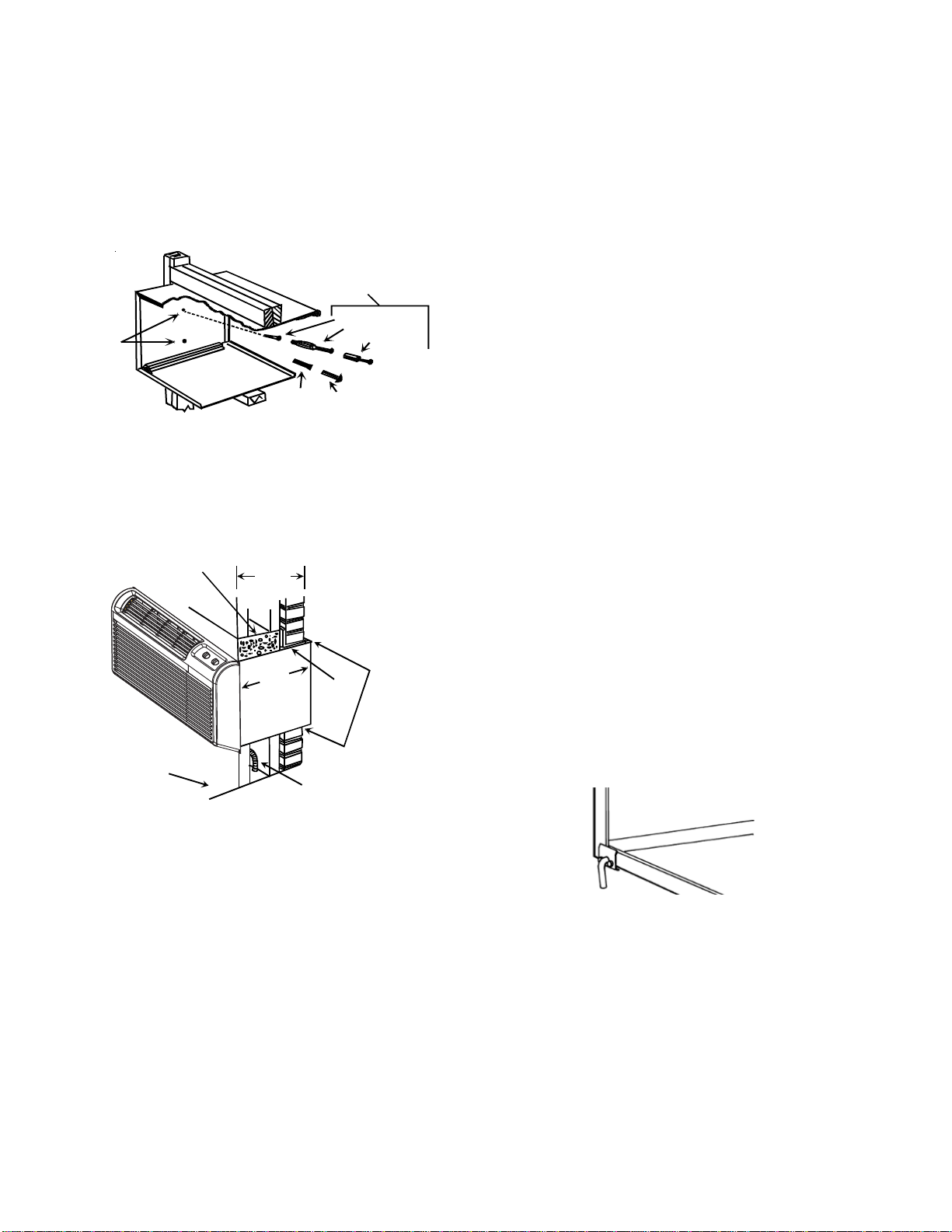
Figure 6
Attaching Wall Sleeve to Opening
•Provide adequate sealing and insulation around the
sleeve after it is installed. See Figure 7 for one
example of construction.
163/4"
426mm
5. Drill two holes in both sides of the wall sleeve so
mounting screws can be secured to wall supports.
See Figure 6 for location of screw holes. DO NOT
DRILL THROUGH BOTTOM OF SLEEVE.
6. Check the level of the wall sleeve and adjust if neces-
sary.
7. Caulk or seal around the outside of the entire sleeve.
8. If the unit chassis is not to be installed immediately,
replace the enclosure panel on the outside opening of
the sleeve to limit weather damage to the building
interior.
Figure 7
Block and Brick Veneer Installation
•Do not use extension cords with the unit.
Power
Supply
Conduit
Caulk
Top,
Bottom,
and Both
Sides
Finish ed
Floor
Concrete
Lintel
Stee l
Lint el
Maximum
(No Accessories)
14 3/4"
375mm
Alternative Fastening
Method(Field Supplied)
Mounting Holes
(Drilled by Installer)
Screws
Plastic
Anchor
Wood Screw
Toggle Bolt
Expansion
Anchor Bolt
Figure10
Condensate Drain
Condensate Drain Kit
Wall Sleeve Installation
Afterthewallopeningischeckedandapprovedforstrength,
location, size, and clearances, install the wall sleeve as
follows:
1. Remove the outside enclosure panel from the wall
sleeve.
3. Locatethesleevewithintherangeofminimumprojec-
tions, as shown in Figure 2, so both sides are at least
the minimum projection from the wall.
2. Slide the wall sleeve into the wall opening. Do not
distortthecabinetshapetofitthewallopening;theunit
chassis must fit snugly and uniformly into sleeve.
4. Check the level of the wall sleeve. For proper drain-
age, the sleeve should be level from side to side and
one-quarter bubble front to back (outside).
Preinstallation Considerations(cont.)
Waterproof barrier should remain in place until the unit
is installed. An accessory metal front panel is available
and sold separately.
A condensate drain tube is included. (Figure 10)
Attached to bottom rear flange of wall sleeve with two
screws provided. For internal drain applications, install
internal drain kit (sold separately) prior to installing the
wall sleeve in the wall. See the drain kit for actual
installation instructions.