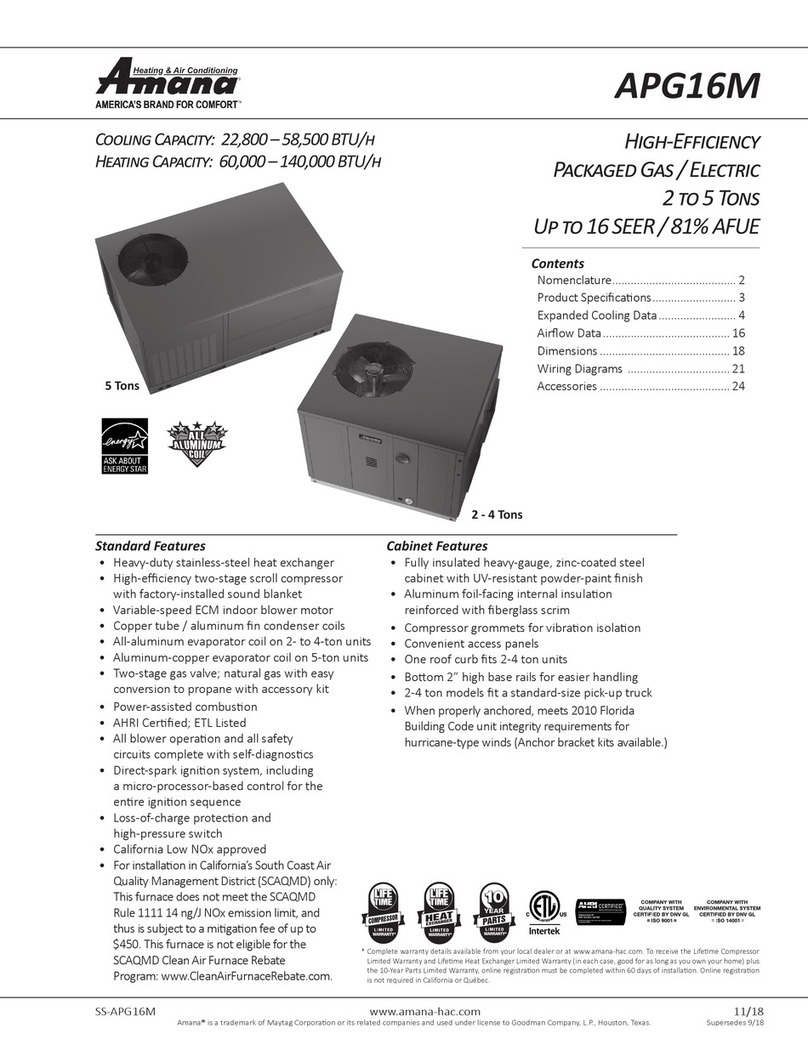
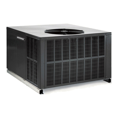
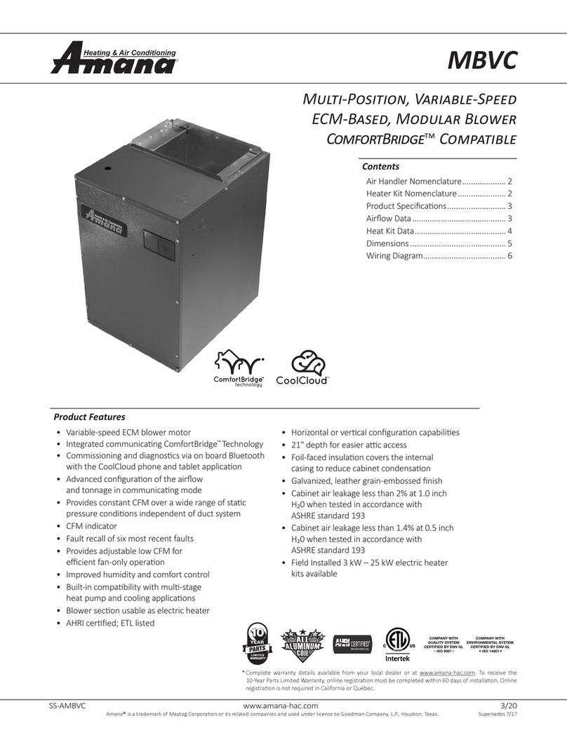
Amana A/GPDM3 Series User manual

Installation Instructions
A/GPDM3 13.4 SEER2 “M” SERIES - Single Package
Dual Fuel Gas-Electric Heating & Cooling Units
ATTENTION INSTALLING PERSONNEL
© 2022
11/2022
RECOGNIZE THIS SYMBOL
AS A SAFETY PRECAUTION.
WARNING
DO NOT BYPASS SAFETY DEVICES
ONLY PERSONNEL THAT HAVE BEEN TRAINED TO INSTALL,
ADJUST, SERVICE, MAINTENANCE OR REPAIR
(HEREINAFTER, “SERVICE”) THE EQUIPMENT SPECIFIED IN
THIS MANUAL SHOULD
SERVICE THE EQUIPMENT. THE MANUFACTURER WILL
NOT BE RESPONSIBLE FOR ANY INJURY OR PROPERTY
DAMAGE ARISING FROM IMPROPER SERVICE OR SERVICE
PROCEDURES. IF YOU SERVICE THIS UNIT, YOU ASSUME
RESPONSIBILITY FOR ANY INJURY OR PROPERTY
DAMAGE WHICH MAY RESULT. IN ADDITION, IN
JURISDICTIONS THAT REQUIRE ONE OR MORE LICENSES
TO SERVICE THE EQUIPMENT SPECIFIED IN THIS
MANUAL, ONLY LICENSED PERSONNEL SHOULD SERVICE
THE EQUIPMENT.
IMPROPER INSTALLATION, ADJUSTMENT, SERVICING,
MAINTENANCE OR REPAIR OF THE EQUIPMENT SPECIFIED
IN THIS MANUAL, OR ATTEMPTING TO INSTALL, ADJUST,
SERVICE OR REPAIR THE EQUIPMENT SPECIFIED IN THIS
MANUAL WITHOUT PROPER TRAINING MAY RESULT IN
PRODUCT DAMAGE, PROPERTY DAMAGE, PERSONAL
INJURY OR DEATH.
WARNING

2
TABLE OF CONTENTS
TO THE INSTALLER ...................................................... 2
TO THE OWNER.............................................................. 2
SHIPPING INSPECTION ................................................. 2
SAFETY INSTRUCTIONS ............................................... 2
ORDERING PARTS ......................................................... 5
GENERAL INFORMATION.............................................. 5
TRANSPORTATION DAMAGE ....................................... 5
PRE-INSTALLATION CHECKS....................................... 6
UNIT INSTALLATION ...................................................... 6
All Installations ........................................................ 6
Ground Level Installations Only............................. 6
Rooftop Installations Only ...................................... 7
Roof Curb Installations Only .................................. 7
Rigging Details ............................................................... 7
Gas Piping....................................................................... 8
LP Conversion.......................................................... 8
High Altitude Derate (U.S. Installations Only) ...... 8
Piping ........................................................................ 8
Electrical Wiring ............................................................. 10
High Voltage Wiring ............................................... 11
Thermostat Controls............................................... 11
Low Voltage Wiring ................................................ 11
Internal Wiring.......................................................... 11
Circulating Air and Filters.............................................. 11
................................................. 11
Horizontal Air Flow .................................................. 12
Ductwork................................................................... 12
Filters ........................................................................ 12
Venting............................................................................. 12
Installation - Flue Hood Exhaust ............................ 12
Installation - Combustion Air Intake Hood ............ 12
Condensate Drain........................................................... 13
Condensate Drain Connection ............................... 13
Heat Pump Operation..................................................... 13
Heat Pump Mode Operation Sequence of Operation
14
Heat Pump to Gas Heat Sequence of Opeation .... 14
Outdoor Thermostat ................................................ 14
Optional Outdoor Thermostat (OTDFPKG-01) ...... 14
Normal Sequences Of Operation .................................. 14
Heating Cycle (Natural Gas/ LP) ............................. 14
Defrost Cycle............................................................ 15
Cooling...................................................................... 15
Fan Only ................................................................... 15
.................. 16
... 16
.............................. 16
Heating Start-up ( Natural Gas / LP)....................... 16
Cooling Start-up....................................................... 19
Suggested Field Testing Troubleshooting ................... 19
Cooling Start-up....................................................... 21
Checking Subcooling .............................................. 21
Checking Superheat ................................................ 21
TROUBLESHOOTING..................................................... 22
MAINTENANCE............................................................... 24
ACCESSORIES AND FUNCTIONAL PARTS ................. 25
APPENDIX ....................................................................... 26
TROUBLESHOOTING..................................................... 26
Ignition Control Diagnostic Indicator Chart .......... 27
Heating Timing Chart............................................... 27
Cooling/heat pump Timing Chart ........................... 27
UNIT DEMENSIONS........................................................ 28
WIRING DIAGRAMs........................................................ 29
BLOWER PERFORMANCE DATA.................................. 31
START-UP CHECKLIST .................................................. 33
TO THE INSTALLER
IMPORTANT NOTE:
TO THE OWNER
SHIPPING INSPECTION
SAFETY INSTRUCTIONS

3
FIRE OR EXPLOSION HAZARD
Failure to follow the safety warnings exactly could result in
serious injury, death or property damage. Never test for
gas leaks with an open flame. Use a commercially available
soap solution made specifically for the detection of leaks
to check all connections. A fire or explosion may result
causing property damage, personal injury or
AVERTISSEMENT
RISQUE D'INCENDIE OU D'EXPLOSION
Si les consignes de sécurité ne sont pas suivies à la
lettre, cela peut entraîner la mort, de graves blessures
ou des dommages matériels. Ne jamais vérifier la
présence de fuites de gaz au moyen d'une flamme nue.
Vérifier tous les raccords en utilisant une solution
savonneuse commerciale conçue spécialement pour la
détection de fuites. Un incendie ou une explosion
risque de se produire, ce qui

4
CARBON MONOXIDE POISONING HAZARD
Failure to follow the steps outlined below for each
appliance connected to the venting system being
placed into operation could result in carbon monoxide
poisoning or death.
The following steps shall be followed for each appliance
connected to the venting system being placed into
operation, while all other appliances connected to the
venting system are not in operation:
1) Seal any unused openings in the venting system.
2) Inspect the venting system for proper size and
horizontal pitch, as required in the National Fuel Gas
Code, ANSI Z223.1/NFPA 54 or the Natural Gas and
Propane Installation Code, CSA B149.1 and these
instructions. Determine that there is no blockage or
restriction, leakage, corrosion and other deficiencies
which could cause an unsafe condition.
3) As far as practical, close all building doors and
windows and all doors between the space in which the
appliance(s) connected to the venting system are
located and other spaces of the building.
4) Close fireplace dampers.
5) Turn on clothes dryers and any appliance not
connected to the venting system. Turn on any exhaust
fans, such as range hoods and bathroom exhausts, so
they are operating at maximum speed. Do not operate
a summer exhaust fan.
6) Follow the lighting instructions. Place the appliance
being inspected into operation. Adjust the thermostat
so appliance is operating continuously.
7) Test for spillage from draft hood equipped
appliances at the draft hood relief opening after 5
minutes of main burner operation. Use the flame of a
match or candle.
8) If improper venting is observed during any of the
above tests, the venting system must be corrected in
accordance with the National Fuel Gas Code, ANSI
Z223.1/NFPA 54 and/or Natural Gas and Propane
Installation Code, CSA B149.1.
9) After it has been determined that each appliance
connected to the venting system properly vents when
tested as outlined above, return doors, windows,
exhaust fans, fireplace dampers and any other gas-fired
burning appliance to their previous conditions of use.
AVERTISSEMENT
RISQUE D'INTOXICATION AU MONOXYDE DE
CARBONESi
appareil
les étapes décrites ci-dessous ne sont pas
suivies pour chacun des appareils raccordés au système
de ventilation au moment de sa mise en marche, cela
peut entraîner une intoxication au monoxyde de
carbone ou la mort. Les étapes suivantes doivent être
suivies pour chacun des appareils raccordés au système
de ventilation au moment de sa mise en marche, alors
que tous les autres appareils raccordés au système de
ventilation ne sont pas en marche :
1) Sceller toutes les ouvertures inutilisées du système de
ventilation.
2) Inspecter le système de ventilation afin de vérifier si
la taille et l'inclinaison par rapport à l'horizontale sont
conformes aux exigences du National Fuel Gas Code,
ANSI Z223.1/NFPA 54 ou du Code d'installation du gaz
naturel et du propane, CSA B149.1 et à ces instructions.
Vérifier qu'il n'y a pas d'obstruction ou de restriction, de
fuite, de corrosion et d'autres problèmes qui pourraient
entraîner une situation dangereuse.
3) Si possible, fermer toutes les portes et fenêtres du
bâtiment ainsi que toutes les portes séparant l'endroit
où se trouvent les appareils raccordés au système de
ventilation et les autres zones du bâtiment.
4) Fermer le registre des foyers.
5) Mettre les sécheuses en marche ainsi que tous les
autres appareils qui ne sont pas raccordés au système
de ventilation. Mettre en marche tous les ventilateurs
de tirage, comme celui des hottes de cuisine et des
salles de bains, et les régler à la puissance maximale. Ne
pas mettre en marche les ventilateurs d'été.
6) Suivre les instructions d'allumage. Mettre en marche
l'appareil soumis à l'inspection. Régler le thermostat de
manière à ce que l'appareil fonctionne en continu.
7) Vérifier la présence de fuite au niveau de l'ouverture
du coupe-tirage des appareils qui en sont dotés après 5
minutes de fonctionnement du brûleur principal. Utiliser
la flamme d'une allumette ou d'une bougie.
8) Si un problème de ventilation est observé pendant
l'un des essais décrits ci-dessus, des correctifs doivent
être apportés au système de ventilation conformément
au National Fuel Gas Code, ANSI Z223.1/NFPA 54 et (ou)
au Code d'installation du gaz naturel et du propane, CSA
B149.1.
9) Une fois qu'il a été déterminé que chaque

5
B10259-216
CO can cause serious illness including permanent brain
damage or death.
Advertencia especial para la instalación de calentadores ó manejadoras
de aire en áreas cerradas como estacionamientos ó cuartos de servicio.
B10259-216
El monóxido de carbono puede causar enfermedades severas
como daño cerebral permanente ó muerte.
Las emisiones de monóxido de carbono pueden circular a través
del aparato cuando se opera en cualquier modo.
B10259-216
RISQUE D'EMPOISONNEMENT AU MONOXYDE DE CARBONE
Le monoxyde de
des
carbone peut causer des maladies graves telles que
dommages permanents au cerveau et meme la mort.
Cette ventilation est nécessaire pour éviter le danger d'intoxication
au CO pouvant survenir si un appareil produisant du monoxyde
de carbone continue de fonctionner au sein de la zone confinée.
ORDERING PARTS
GENERAL INFORMATION
This unit is approved for outdoor installation ONLY.
TRANSPORTATION DAMAGE
1.
2.
3.
4.
a.
c.

6
NOTE:
Unit installation
PRE-INSTALLATION CHECKS
UNIT INSTALLATION
WARNING
controls.

7
Outside Slab Installation
NOTE:
MODEL ROOF CURB
RIGGING DETAILS
4 holesbase
frame corners.
less60”.

8
Rigging
GAS PIPING
IMPORTANT NOTE:
NOTE:
Propane
INLET GAS PRESSURE
IMPORTANT NOTE:
NOTE:
IMPORTANT NOTE
1.
2.
3.
4.

9
Len
g
th of
Pipe in Feet 1/2 3/4 11 1/4 1 1/2
10 132 278 520 1050 1600
20 92 190 350 730 1100
30 73 152 285 590 980
40 63 130 245 500 760
50 56 115 215 440 670
60 50 105 195 400 610
70 46 96 180 370 560
80 43 90 170 350 530
90 40 84 160 320 490
100 38 79 150 305 460
Pressure = .50 PSIG or less and Pressure Drop of 0.3" W.C. (Based
on 0.60 Specific Gravity Gas)
Natural Gas Capacity of Pipe
in Cubic Feet of Gas Per Hour (CFH)
Nominal Black Pipe Size (inches)
BTU H Furn ace Inp ut
Heating Value of G as (BTU/C ubic Foot)
CF H =
Proper Piping Practice
NOTE:
Proper Piping Practice
Propane Gas Installations
IMPORTANT NOTE:
all gas appliances in operation. Maintaining proper gas
1.
or containers.
2. Proper pressure regulation.
3.
gas suppliers.

10
200 PSIG
Maximum
5 to 15 PSIG
(20 PSIG Max.) Continuous
11" W.C.
Second Stage
Regulator
First Stage
Regulator
Sizing Between First and Second Stage Regulator
Maximum Propane Capacities listed are based on 1 PSIG Pressure Drop at 10
PSIG Setting. Capacities in 1,000 BTU/HR
3/8" 1/2" 5/8" 3/4" 7/8" 1/2" 3/4"
30 309 700 1,303 2,205 3,394 1,843 3,854
40 265 599 1,115 1,887 2,904 1,577 3,298
50 235 531988 1,672 2,574 1,398 2,923
60 213 481896 1,515 2,332 1,267 2,649
70 196 446824 1,394 2,146 1,165 2,437
80 182 412767 1,297 1,996 1,084 2,267
90 171 386719 1,217 1,873 1,017 2,127
100 161 365679 1,149 1,769 961 2,009
150 130 293546 923 1,421 772 1,613
200 111 251467 790 1,216 660 1,381
250 90 222414 700 1,078 585 1,224
300 89 201378 634 976 530 1,109
350 82 185345 584 898 488 1,020
400 76 172321 543 836 454 949
To convert to Capacities at 15 PSIG Settings -- Multiply by 1.130
To convert to Capacities at 5 PSIG Settings -- Multiply by 0.879
PIPE OR
TUBING
LENGTH,
FEET
NOMINAL PIPE SIZE,
SCHEDULE 40
TUBING SIZE, O.D., TYPE L
Sizing Between Single or Second Stage Regulator and Appliance*
Maximum Propane Capacities Listed are Based on 1/2" W.C. Pressure Drop at
11" W.C. Setting. Capacities in 1,000 BTU/HR
3/8" 1/2" 5/8" 3/4" 7/8" 1/2" 3/4" 1" 1-1/4" 1-1/2"
10 49 110 206 348 539 291 608 1,146 2,353 3,525
20 34 76 141 239 368 200 418 788 1,617 2,423
30 27 61 114 192 296 161 336 632 1,299 1,946
40 23 52 97 164 253 137 284 541 1,111 1,665
50 20 46 86 146 224 122 255 480 985 1,476
60 19 42 78 132 203 110 231 436 892 1,337
80 16 36 67 113 174 94 198 372 764 1,144
100 14 32 59 100 154 84 175 330 677 1,014
125 12 28 52 89 137 74 155 292 600 899
150 11 26 48 80 124 67 141 265 544 815
200 10 22 41 69 106 58 120 227 465 697
250 9 19 36 61 94 51 107 201 412 618
300 8 18 33 55 85 46 97 182 374 560
350 7 16 30 51 78 43 89 167 344 515
400 7 15 28 47 73 40 83 156 320 479
*DATA IN ACCORDANCE WITH NFPA PAMPHLET NO. 54
NOMINAL PIPE SIZE,
SCHEDULE 40
TUBING SIZE, O.D., TYPE L
PIPE OR
TUBING
LENGTH,
FEET
ELECTRICAL WIRING
NOTE:
sources.
electrical panel.
IMPORTANT NOTE:

11
Rated Voltage Minimum Supply Voltage Maximum Supply Voltage
208/230V 197 253
Maximum Allowable
Length in Feet to Limit
Voltage Drop to 2%
15 20 25 30 35 40 45 50
Supply Wire Length - Feet
200 64443322
150 86644433
100 10 8866644
50 14 12 10 88866
sensor.
kit.
IMPORTANT NOTE:
A/GPDM3
TERMINAL WIRE
24-48
THERMOSTAT
Green
1.
2.
3.
CAUTION
WARNING
CIRCULATING AIR AND FILTERS

12
panels in place.
NOTE:
Filter Installation
IMPORTANT NOTE:
UNIT 2 TON 2 1/2 TON 3 TON 3 1/2 / 4
TON
Min.Filter
VENTING
1.
2.
3.
4.
1.
2.

13
CONDENSATE DRAIN
DRAIN
CONNECTION
MUMINIM"2TINU
FLE
XIBLE
T
UBING-HOSE
OR
PIPE
3" MINIMU
M
A POSITIVE LIQUID
SEAL IS REQUIRED
Drain Connection
HEAT PUMP OPERATION

14
1.
2.
3.
4.
Note:
1.
2.
3.
4.
NORMAL SEQUENCES OF OPERATION
1.
2.
purge.
3.
spark ignition.
NOTE:
4.
NOTE:

15
NOTE:
9.
NOTE
space.
NOTE:
position.
1.
2.
3.
4.
NOTE
NOTE
1.
2.
3.
1.
2.
3.

16
section.
NOTE:
EEM Motor
NOTE:
START-UP, ADJUSTMENTS, AND CHECKS
Rollout Protection Control
Rollout Protection
Secondary
Control Limit
Back of Unit
1.
2.
3.
4.

17
9.
unit.
10.
11.
12.
NOTE:
Inlet
Pressure
Boss
Low Fire
Regulator
Adjust
Manometer
Manometer
Hose
High Fire Regulator
Adjust Regulator
Vent
Outlet
Pressure Boss
Open to
Atmosphere
On/OffSwitch
HighFireCoil
Terminal(HI)CoaxialCoil
Terminal(M)
Common
Terminal(C)
White-Rodgers Model 36G54 Connected to Manometer
Mode
10.0
1.
Mode
10.0
Measuring Inlet Gas Pressure
2.
INLET GAS PRESSURE
Propane
NOTE:
Manometer
Manometer
Hose
High Fire Regulator
Adjust Regulator
Vent
On/Off Switch
HighFire Coil
Terminal (HI) Coaxial Coil
Terminal (M)
Common
Terminal(C)
White-Rodgers Model 36J54 Connected to Manometer
Mode
3.5
1.

18
3.
Example:
NOTE:
4.
Note:
1.
2.
position.
3.
4.
Heating
1.
2.
2.
3.
4.
9.
10.
11.
12.
13.
14.
Manifold Gas Pressure
Gas Range Nominal
Propane
1.
unit.
2.

19
3.
4.
NOTE:
SUGGESTED FIELD TESTING
TROUBLESHOOTING
NOTE:
NOTE:
1.
2.
NOTE:
3.
4.
9.
NOTE:
1.
2.
3.
4.
1.
2.

20
NOTE:
NOTE:
plate.
1.
Total External Static
2.
3.
NOTE:
4.
WARNING
T
O AVOID PERSONAL INJURY OR DEATH DUE TO ELECTRIC SHOCK, REMOVE
ELECTRICAL POWER FROM THE UNIT BEFORE CHANGING SPEED TAPS ON THE
BLOWER MOTOR.
NOTE:
Color
Tap
Color
Tap
T1
T3
Cool/HP
T2
T4
Cool/HP
GAS HEATING
COOLING
NOTE
cooling operation
This manual suits for next models
9
Table of contents
Other Amana Fan manuals
Popular Fan manuals by other brands

Monte Carlo Fan Company
Monte Carlo Fan Company 5OBR52 Series owner's manual

Modine Manufacturing
Modine Manufacturing Atherion ERM Installation and service manual

BLAUBERG Ventilatoren
BLAUBERG Ventilatoren BLABDUCTO Series user manual

Rubine
Rubine Raffica 56-5BL user manual

ansio
ansio 1100 instruction manual

Armstrong
Armstrong HLAR Series instructions

CFM
CFM DVK-0910 brochure

Sealey
Sealey HVD24P instructions

Nibe
Nibe SAM 40 Installer manual

iLiving
iLiving ILG8SF10V-ST owner's manual

Kooltronic
Kooltronic Guardian Series installation instructions

LUCCI Air
LUCCI Air AIRFUSION AIRLIE II ECO Series Installation, operation, maintenance & warranty information