manuals.online logo
Brands
  1. Home
  2. •
  3. Brands
  4. •
  5. Amana
  6. •
  7. Range
  8. •
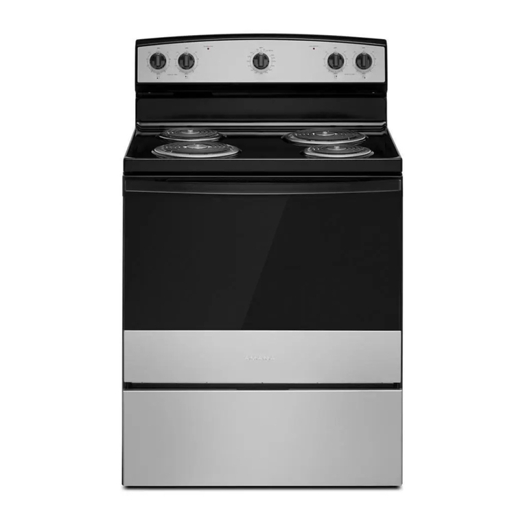
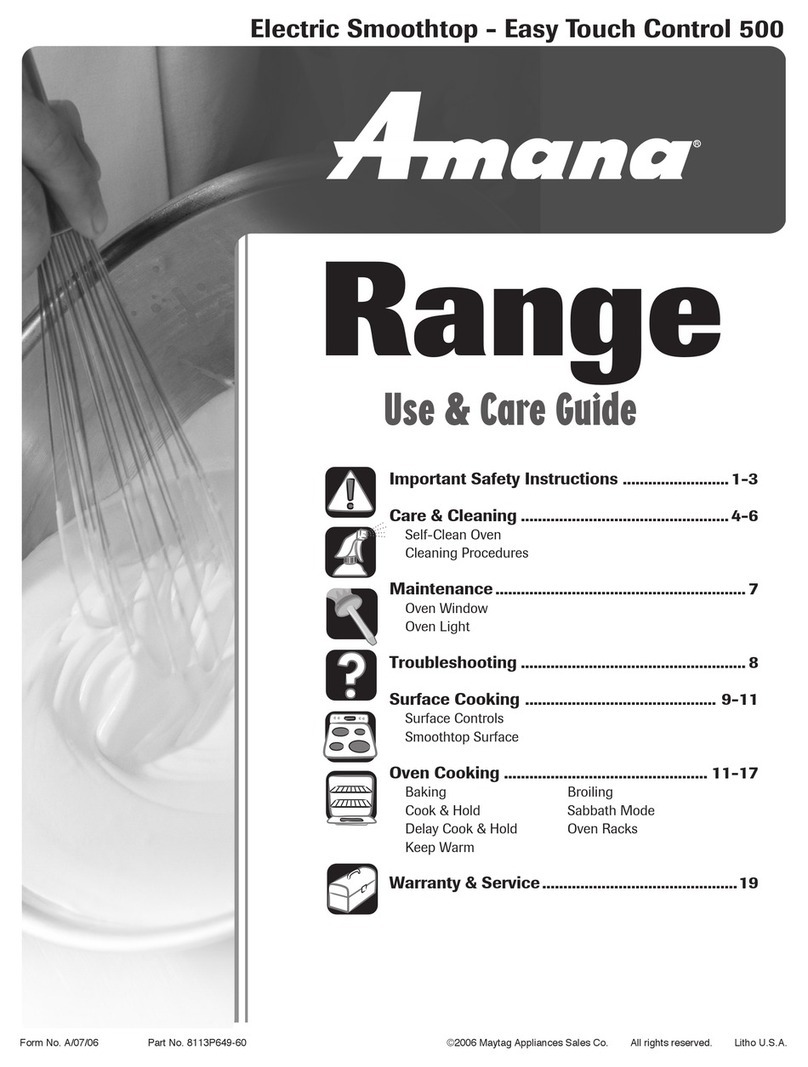
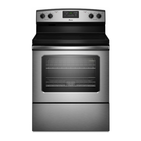
  9. Amana ACF422GAB User manual

Amana ACF422GAB User manual

This manual suits for next models

7

Other Amana Range manuals

Amana AES3760BAQ User manual

Amana

Amana AES3760BAQ User manual

Amana The BigOven ACF4255A User manual

Amana

Amana The BigOven ACF4255A User manual

Amana AGG200AAW0 User manual

Amana

Amana AGG200AAW0 User manual

Amana AER5715QA User manual

Amana

Amana AER5715QA User manual

Amana ACF4225AB User manual

Amana

Amana ACF4225AB User manual

Amana YAER6303MFW User manual

Amana

Amana YAER6303MFW User manual

Amana AGR3530AAW User manual

Amana

Amana AGR3530AAW User manual

Amana AER5712BA User instructions

Amana

Amana AER5712BA User instructions

Amana AER5522VA Parts list manual

Amana

Amana AER5522VA Parts list manual

Amana 8113P732-60 User manual

Amana

Amana 8113P732-60 User manual

Amana AGR4412AD Parts list manual

Amana

Amana AGR4412AD Parts list manual

Amana YACR4303MFS5 User manual

Amana

Amana YACR4303MFS5 User manual

Amana AGR5630BD User manual

Amana

Amana AGR5630BD User manual

Amana AGP200VDW User manual

Amana

Amana AGP200VDW User manual

Amana AER5844VA User manual

Amana

Amana AER5844VA User manual

Amana AGDS901 User manual

Amana

Amana AGDS901 User manual

Amana ACR4530BA Use and maintenance manual

Amana

Amana ACR4530BA Use and maintenance manual

Amana W10130752B User manual

Amana

Amana W10130752B User manual

Amana AGR6603SFS User manual

Amana

Amana AGR6603SFS User manual

Amana AGR5844VDS4 User manual

Amana

Amana AGR5844VDS4 User manual

Amana AGDS902SS User manual

Amana

Amana AGDS902SS User manual

Amana AER3311WA User manual

Amana

Amana AER3311WA User manual

Amana AGR3311WD User manual

Amana

Amana AGR3311WD User manual

Amana W10533015B User manual

Amana

Amana W10533015B User manual

Popular Range manuals by other brands

Maytag MGR5875QDW - 30 Inch Gas Range Use and care guide

Maytag

Maytag MGR5875QDW - 30 Inch Gas Range Use and care guide

Frigidaire FFGF3024SS use & care

Frigidaire

Frigidaire FFGF3024SS use & care

Capital Precision Series GCR484W Specifications

Capital

Capital Precision Series GCR484W Specifications

Officine Gullo GGS8P Installation and use instruction

Officine Gullo

Officine Gullo GGS8P Installation and use instruction

LG LSD4913 Series owner's manual

LG

LG LSD4913 Series owner's manual

Kenmore 4101 - Elite 30 in. Slide-In Electric Range installation instructions

Kenmore

Kenmore 4101 - Elite 30 in. Slide-In Electric Range installation instructions

Moffat Blue Seal Evolution G576 Technical data sheet

Moffat

Moffat Blue Seal Evolution G576 Technical data sheet

CornuFé C1NF user guide

CornuFé

CornuFé C1NF user guide

GE JGS650SEFSS Dimensions and installation information

GE

GE JGS650SEFSS Dimensions and installation information

LG LDG3015ST Manual De Propietario

LG

LG LDG3015ST Manual De Propietario

Whirlpool RF350PXP Use and care guide

Whirlpool

Whirlpool RF350PXP Use and care guide

Samsung FCQ321HTUW Service manual

Samsung

Samsung FCQ321HTUW Service manual

Kenmore 790.45712 Use & care guide

Kenmore

Kenmore 790.45712 Use & care guide

Wolf CHR CHSSR owner's manual

Wolf

Wolf CHR CHSSR owner's manual

Smeg Built-in Microwave Oven Instructions for the user

Smeg

Smeg Built-in Microwave Oven Instructions for the user

Zanussi ZCG054G user manual

Zanussi

Zanussi ZCG054G user manual

GE JCSS630 quick start guide

GE

GE JCSS630 quick start guide

Samsung NX58M9960P series installation manual

Samsung

Samsung NX58M9960P series installation manual

manuals.online logo
manuals.online logoBrands
  • About & Mission
  • Contact us
  • Privacy Policy
  • Terms and Conditions

Copyright 2025 Manuals.Online. All Rights Reserved.

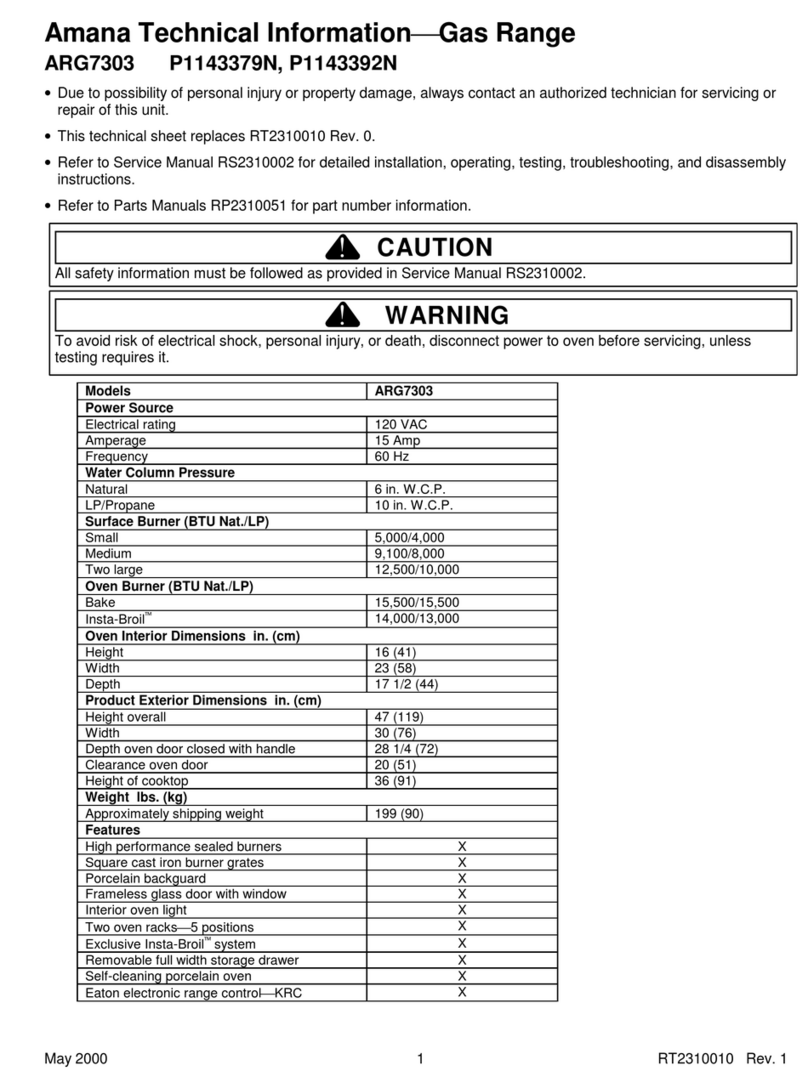
Amana Technical InformationElectric Range
October 2001 36-32089901-0
1
ACF422GAB PACF422GAB1
ACF422GAC PACF422GAC1
ACF422GAS PACF422GAS1
ACF422GAW PACF422GAW1
• Due to possibility of personal injury or property damage, always contact an authorized technician for servicing or
repair of this unit.
• Refer to Service Manual RS2320006 for detailed installation, operating, testing, troubleshooting, and disassembly
instructions.
• Refer to Parts Manual RP2320100 for complete part number information.
CAUTION
!
All safety information must be followed as provided in Service Manual RS2320006.
!WARNING
To avoid risk of electrical shock, personal injury or death; disconnect power to oven before servicing, unless
testing requires power.
Model ACF422GA* Model ACF422GA*
Power Source @ 240 V / 208V Cooktop Surface −Upswept
Electrical rating 240 VAC ..........
208 VAC ..........
9.5 KW
7.3 KW
Oversized glass ceramic SpillsaverX
Amperage 40 Amp Frameless glass door with window X
Frequency 60 Hz Interior oven light X
Element Wattage @ 240 V / 208V Two oven racks −6 positions X
6-inch ribbon radiant 1,200 / * Removable full width storage drawer X
8-inch ribbon radiant 2,000 / * Electronic control with mylar overlay X
Product Exterior Dimensions in. (cm)
Oven Wattage @ 240 V / 208V Height overall 47 (119)
Bake 6 pass 2,800 / * Width 30 (76)
Broil 6 pass 3,000 / * Depth oven door closed with handle 28 13/16 (73)
Oven Interior Dimensions in. (cm)
Clearance oven door 22 (56)
Height 19 (48) Height of cooktop 36 (91)
Width 24
1/4(61) Weight lbs. (kg)
Depth 19 (48) Approximately shipping weight 171 (78)
* −Rating of 208 VAC is approximately 80% of 240 VAC value.
https://appliancetechmanuals.com
Component Testing Procedures
!WARNING
To avoid risk of electrical shock, personal injury or death; disconnect power to oven before servicing, unless
testing requires power.
36-32089901-0 October 2001
2
Illustration Component Test Procedure Results
31823701
Oven light socket Remove one wire from receptacle
and test resistance of terminals.
Measure voltage at oven light.
Indicates continuity with bulb screwed in.
120 VAC, see wiring diagram for terminal
identification.
If no voltage is present at oven light, check
wiring or light switches.
31722801
Oven indicator light
and
Surface indicator light
Remove one lead from switch
terminal and measure resistance
across terminals.
Measure voltage at indicator light.
Switch closed: 0 Ω
Switch open: Infinite resistance
If voltage is present and light does not
operate. Replace light.
If no voltage is present at indicator light
check wiring.
31938901−1200 W
31939101−2000 W
Ribbon radiant
elements, limiters are
not replaceable.
Remove one wire lead from element
and measure resistance of the
element.
Verify supply voltage ........................
Continuity, if not replace.
1200W: 44 to 49 ΩApproximately
2000W: 26 to 30 ΩApproximately
240 VAC
31926701
31926702
Infinite switch Remove wiring from terminals H1
and H2. Connect Volt ohms meter to
H1 and H2.
Measure the following for voltages at
LO, MED, HI:
H1 to H2 .........................................
Time On Time Off
LO 5% 95%
MED (4-5) 50% 50%
HI 100% 0%
240 VAC, if not replace switch.
32078201
Control limit
Normally Closed
Verify proper operation.
Closed.......... 215°F .......................
Open ............ 245°F .......................
If open at room temperature, replace.
Continuity
Infinite
31967101
Bake element Disconnect wire leads to element
and measure resistance of terminals.
Measure voltage at bake element.
Continuity, approximately 20 Ω,
if not replace.
240 VAC, see wiring diagram for terminal
identification.
If no voltage is present at bake element
check wiring.
31967302
Broil element Disconnect wire leads to element
and measure resistance of terminals.
Measure voltage at broil element.
Continuity, approximately 19 Ω,
if not replace.
240 VAC, see wiring diagram for terminal
identification.
If no voltage is present at broil element
check wiring.
31954301
Oven temperature
sensor
Measure resistance.
Approximately 1100 Ωat room
temperature 75°F.
31946302
Hinge Carefully open the door to full
position.
Slide hinge lock to lock position.
Close the door to first stop position
and raise door from hinge receivers.
Hinge replacement requires door
disassembly.
CAUTION
!
Do not place hands in hinge area when
oven door is removed. Hinge can snap
closed and pinch hands or fingers.
https://appliancetechmanuals.com
Component Testing Information
!WARNING
To avoid risk of electrical shock, personal injury or death; disconnect power to oven before servicing, unless
testing requires power.
October 2001 36-32089901-0
3
Illustration Component Test Procedure Results
32040901
Auto latch assembly Motor switch
Unlocked ....................................
Locked........................................
Door switch
Door closed ................................
Door open...................................
COM −N.O.continuity
COM −N.O.open
COM −N.C.continuity
COM −N.C.open
32088501
PIN 1
E4
E2
E1 J2
J1
E5
E7
E3
Electronic range
control
On power-up lock
light will blink for
approximately 25
seconds, while
control is verifying
lock latch position.
On power up, if
sensor has failed.
No F - Code will be
displayed.
No oven functions
will start.
Measure voltage at terminals
J2−E7 (L1) and E2 (NEU) ...............
Relay drive requirements
BakeBA to L2 ..............................
Broil BR to L2 ..............................
Bake ..............................................
Broil ...............................................
Clean
Stage 1 ..........................................
Stage 2 ..........................................
Time (Adjustable)...........................
Failure codes:
F1-Control malfunction.....................
F2-Oven over temperature...............
F3-Oven temperature sensor
Open or Shorted .........................
F9-Door latch circuit malfunction......
Temperature Calibration .................
120 VAC should be indicated, verifying
voltage to control.
240 VAC, if not replace control.
75% bake element 25% broil element
100% broil element
Time controlled 60 minutes 100% broil
50% bake element and 50% broil element
2 hours minimum to 4 hours maximum
Verify voltage to control.
If no voltage is present, check wiring.
If voltage is present, replace control.
Check sensor resistance and wiring.
Replace control if sensor and wiring are
good.
Check sensor resistance and wiring.
Replace sensor, if wiring is good.
Check latch switch and associated wiring.
Turn oven control to OFF position.
Press and hold both slew pads for 5 sec.
Use slew pads to adjust temp setting.
After 5 sec. of no input the mode is exited.
Calibration will be retained through a
power failure.
Mylar Overlay
32025901−B Black 32025902−C Bisque 32025903−W White
OVEN
PREHEAT LOCKED PUSH TO TURN
BAKE
OVEN
CLEAN OFF WM
BROIL
LIGHT
TIMER
ON OFF
COOK
CLEAN
TIME
START
COOK
CLEAN
OV E N T EM P
CLOCK
RECALL
https://appliancetechmanuals.com
Wiring Diagram and Schematic
!WARNING
To avoid risk of electrical shock, personal injury or death; disconnect power to oven before servicing, unless
testing requires power.
36-32089901-0 October 2001
4
DIAGRAM
BK WH
L2 NL1
RD
WARNING
- DISCONNECT POWER AT MAIN
FUSE OR CIRCUIT BREAKER BEFORE SERVICING.
FAILURE TO DO SO COULD RESULT IN SERIOUS
INJURY OR DEATH.
- ELECTRICAL SHOCK HAZARD
14 or 16GA RD
14 or 16GA BK
RIGHT
SURFACE
NEON
14 or 16
GA RD
14GA BK
SURFACE ELEMENTS SURFACE ELEMENTS
14 or 16GA BK
WH
SCHEMATIC
35-32042801-0
RANGE CONDITIONS SHOWN:
ELEMENTS OFF AND AT ROOM TEMPERATURE.
DOOR UNLATCHED AND CLOSED.
OVEN
LIGHT
14
GA
RD
*
-RISQUE DE CHOC ELECTRIQUE
-DEBRANCHER L'ALI MENTATION EL ECTRIQUE.
AVANT D'ENTRETENIR CETTE UNITE.
DANGER
LE MANQUE DE RESPECT DE CETTE CONSIGNE POURRAIT
AVOIR COMME RESULTAT UNE BLESSURE GRAVE OU MORTELLE.
MAIN
TERMINAL
BLOCK
(L1)
RED
WHITE
(N)
(L2)
BLACK
GROUND
STRAP
LEFT
SURFACE
NEON
WH VT
VT
VT
RED
ORANGE
YELL OW
GREEN
BLUE
VIOLET
BLACK
BROWN
GRAY
WHITE
RD
OR
YL
GN
BU
VT
BK
BR
GY
WH
COLOR
COLOR
SYMBOL
JAUNE
BLANC
GRIS
MARRON
NOIR
VIOLET
BLEU
VERT
ORANGE
ROUGE
COULEUR
OR WH
NOTES:
*
4. DENOTES OPTIONAL EQUIPMENT AND RELATED WIRING NOT
SUPPLIED ON SOME MODELS.
1. ALL INTERNAL WIRES ARE 18GA, 125°C XL UNLESS OTHERWISE
NOTED. SF2 IS SEW-2/SF2 200°C RATED.
3. SEE SERIAL PLATE FOR INPUT VOLTAGE/WATTAGE RATING.
5. ELEMENT WATTAGES VARY BY MODEL. REPLACEMENT ELEMENTS
MUST HAVE SAME WATTAGE AS ORIGINAL ELEMENTS.
6. FOR RANGE INSTALLATION, USE COPPER WIRE ONLY.
CHASSIS
GROUND
GREEN
or
BARE
*
(FOUR WIRE
INSTALLATIONS
ONLY)
GROUND
STRAP
GROUND STRAP
NOT USED FOR
FOUR WIRE
INSTALLATIONS
LFRR
P
RF LR
L2
H2
L1
H1
1a
2a
1a
2a
1a
2a
1a
2a
1b 1b 1b
2b 2b 2b
1b
2b
2500W 1500W 2000W 1200W
WH
LEFT
SURFACE
NEON
RIGHT
SURFACE
NEON
H1
H2
SWITCH
P
L1
L2
H1
H2
SWITCH
PL1L2
1a
2a
1b
2b
1a
2a
1b
2b
OR
VT
RD
H1
H2
SWITCH
R.F.
P
L1
L2
H1H2
SWITCH
R.R.
P
L1
L2
1a
2a
1b
2b
1a
2a
1b
2b
BR BR
OR
SF2 RD
SF2
SF2
SF2
SF2
SF2
SF2
SF2
16GA 16GA
16GA
RD
YL YL
WH
2. ALL REPLACEMENT WIRES MUST HAVE SAME RATING AS ORIGINAL WIRE.
(NOTE 7)
7. GROUND STRAP NOT USED FOR FOUR WIRE INSTALLATIONS.
*
14GA RD
(NOTE 5)
*
VT
VT
RD
WH
OVEN DR
LT SW
COM 1
NC 2
DR LATCH
SW
OR
WH
OR
OR
VT
L.R. L.F.
OR
VT
VT
SF2
SF2
VT
OR
TEMPERATURE
SENSOR
WH/RD
BU
OR
VT
L1-E7 COM
J1
NO
NC
RD
WH
BROIL
3000W
BAKE
2800W
BROIL E3
BAKE-E5
BAKE
ELEMENT
BROIL
ELEMENT BU
16GA
BR
AUX
WH
16GA
YL
L1 MDL
RD
14
GA
BR BA
BU
NEU
YL
16
GA
BR
16
GA
1
3
4
5
BU
TEMPERATURE
SENSOR
2 1
2 1
2
PIN
CIR
2
SOCKET
CIR
WH
RD
VT
WH/RD
GY
OR
ERC GENESIS
OVEN
LIGHT
14
34
OR GY
5
6
OR
*
5
6
(N)
150 °C
COM1
NO3
150 ° C
OR
GY
NEU-E2
OR
GY
16 GA
SF2
BU BU
16 GA
SF2
BK/WH
2
BU
BR
YL
SF2
CHASSIS
GROUND
14 GA GN
BACKGUARD
GROUND
*PL2
H2
L1
H1
PL2
H2
L1
H1
PL2
H2
L1
H1
GY
6
5
3
2
1
LKSW
DRSW
ERC GENESIS
OR
M
WH
LATCH
AUX E1
MDL E4
NO
WH
21
32
MOTOR
DOOR
LOCK
J1
6
BU
VT
6
PIN
CIR
BU WH
VT
WH
BU
WH
BU
WH
E2 E1
E7 E4 E3 E5
BU
BK
WH
BK
NC
OVEN HIGH
LIMIT
14
GA
BK
NC
BU
BU
OVEN HIGH
LIMIT
18 or 20GA
32042801
https://appliancetechmanuals.com