Amatrol 890-FTS1 User manual

L17401-CL06JEN-E2-S02, REV. C INTRODUCTION TO TROUBLESHOOTING
Copyright © 2019 Amatrol, Inc.
S02-1
SKILL 2 TEST A MANUAL SWITCH
Procedure Overview
In this procedure, you will test the operation of a pushbutton switch and a
selector switch. To do this, you will insert faults into each component using the
890-FTS1 Troubleshooting System or manual fault plugs.
1. Perform a lockout/tagout on the safety switch of the 85-MT5.
NOTE
If you are using manual fault insertion, skip to step 3.
2. Perform the following substeps to set up the 890-FTS1 Troubleshooting
System with a power cord.
A. Make sure the troubleshooting system is plugged into a wall outlet.
B. Make sure the troubleshooting system is turned off.
C. Locate the fault terminals at the rear of the Operator Station on the 85-MT5
trainer.
D. Make sure that the fault cables are connected to the 85-MT5 Operator
Station panel in the standard configuration as shown on the back of the
Operator Station panel and in figure 2-1.
OPERATOR STATION FAULT CONNECTION TABLE
Fault Cable Number Connected to Station
Fault Terminal
66
77
88
99
10 10

L17401-CL06JEN-E2-S02, REV. C INTRODUCTION TO TROUBLESHOOTING
Copyright © 2019 Amatrol, Inc.
S02-2
SKILL 2 TEST A MANUAL SWITCH
Figure 2-1. Standard Configuration for Operator Station Fault Cables
3. If you are using manual fault insertion, make sure each of the fault terminals
on the operator station has a standard jumper plug inserted.
4. Perform the following substeps to test the N.O. contacts of pushbutton PB1
in an out-of-circuit test.
A. Locate your multimeter and set it to measure resistance.
B. Make sure that no leads are connected to the plug-in jacks on the front
panel of the Operator Station. If there are, disconnect them.
890-FTS1
TROUBLESHOOTING
SYSTEM
FAULT
TERMINALS
OPERATOR STATION
6
7
8
9
10
6
7
8
9
10

L17401-CL06JEN-E2-S02, REV. C INTRODUCTION TO TROUBLESHOOTING
Copyright © 2019 Amatrol, Inc.
S02-3
SKILL 2 TEST A MANUAL SWITCH
C. Place the multimeter leads into the terminals of the N.O. contacts of PB1,
as shown in figure 2-2, and record the measurement.
PB1 Resistance (not pressed)____________________________ (Ohms)
If the pushbutton is good, the resistance should be infinite (open). This is
the first step of testing the pushbutton. The next step is to test it when the
operator is pressed.
Figure 2-2. Pushbutton PB1 N.O. Contacts Out-of-Circuit Test
COM
Ω
Ω
OPERATOR STATION
PN 17320
EARTH
GND
SS1
PB3
PB2
PB1

L17401-CL06JEN-E2-S02, REV. C INTRODUCTION TO TROUBLESHOOTING
Copyright © 2019 Amatrol, Inc.
S02-4
SKILL 2 TEST A MANUAL SWITCH
D. Press and hold the pushbutton and then record the resistance.
PB1 Resistance (pressed)_______________________________ (Ohms)
If the pushbutton is good, the resistance should be at or near zero. This
shows that the contacts are closing when the operator is pressed. This
pushbutton is good.
On a machine, these measurements are made by placing the multimeter
leads on the pushbutton’s N.O. contact block, as shown in figure 2-3.
NOTE
The contact blocks for the pushbutton switches and the selector switch
simply snap into place. This makes them easy to replace when necessary.
Figure 2-3. Actual Measurement of Contacts
5. Perform the following substeps to insert a fault into PB1 in the single fault
mode and test it.
A. If you are using manual fault insertion, obtain a short fault plug and plug
it into the station fault terminal labeled 6 in place of the standard jumper
plug. The station fault terminals are located on the back of the station
panel. Then, skip to substep J. If not, continue with substep B.
COM
Ω
Ω
N.O. CONTACT
BLOCK

L17401-CL06JEN-E2-S02, REV. C INTRODUCTION TO TROUBLESHOOTING
Copyright © 2019 Amatrol, Inc.
S02-5
SKILL 2 TEST A MANUAL SWITCH
B. If you are using the FaultPro Troubleshooting System, turn on the system.
C. Start up the FaultPro software and login using your ID number and
password.
D. If necessary, open the Class folder by clicking the +to the left of the class
name.
E. Open the LAP 6: Introduction to Troubleshooting option.
F. Select the Skill 2: Test a Manual Switch option.
G. Click the Single Fault Mode button.
The FaultPro software will open the Single Fault Mode window.
H. Type 6in the Enter Fault field.
I. Press the Enter key or click to activate the fault.
Fault 6 is now active. You should observe that the fault status field changes
from “No Faults Active” to “Fault 6 is Active.”
Fault 6 is a short in the N.O. contacts of PB1.
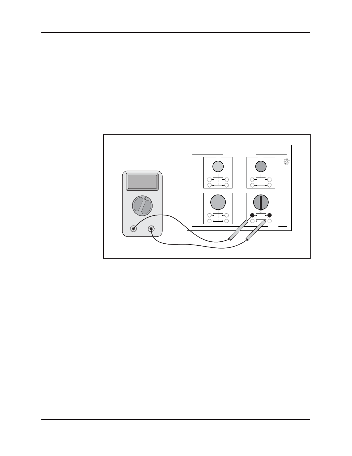
J. Repeat step 4 to test the pushbutton and record your measurements.
PB1 Resistance (not pressed) ___________________________ (Ohms)
PB1 Resistance (pressed)_______________________________ (Ohms)
Component Status _________________________________ (Good/Bad)
This time you should find that the multimeter measures zero resistance
in both conditions. This means that there is a short in the contacts. The
component is bad.
K. Click the Clear Fault button to clear the fault or remove the fault plug.
With the FaultPro software, the fault will clear and the fault status field
should change to “Fault 6 is cleared.”
If you are using manual fault insertion, remove the short plug from
terminal 6 and replace it with the standard jumper plug.
L. Repeat the pushbutton test in step 4.
PB1 Resistance (not pressed) ___________________________ (Ohms)
PB1 Resistance (pressed) ______________________________ (Ohms)
Component Status _________________________________ (Good/Bad)
The resistance should change this time when the pushbutton is pressed.
This means it is good again.
Now proceed to the next substep to test an open type fault in N.O. contacts.
M. If you are using manual fault insertion, locate the open fault plug and plug
it into station fault terminal 7. Then, go to substep P. If you are using the
FaultPro software, continue with substep N.
N. Type 7to insert fault 7 in the Enter Fault field.

L17401-CL06JEN-E2-S02, REV. C INTRODUCTION TO TROUBLESHOOTING
Copyright © 2019 Amatrol, Inc.
S02-6
SKILL 2 TEST A MANUAL SWITCH
O. Press the Enter key or click on the to activate the fault.
Fault 7 is now active. You should observe that the fault status field changes
from “Fault 6 is cleared” to “Fault 7 is Active.”
Fault 7 is an open in the N.O. contacts of PB1.
P. Repeat step 4 to test the pushbutton and record your measurements.
PB1 Resistance (not pressed) ___________________________ (Ohms)
PB1 Resistance (pressed) ______________________________ (Ohms)
Component Status _________________________________ (Good/Bad)
This time you should find that the multimeter measures infinite resistance
in both conditions. This means that there is an open in the contacts. The
component is bad.
Q. Click the Clear Fault button to clear the fault or remove the fault plug.
With the FaultPro software, the fault will clear and the fault status field
should change to “Fault 7 is cleared.”
If you are using manual fault insertion, remove the open plug from
terminal 7 and replace it with the standard jumper plug.
6. Now test the N.C. contacts of PB2. Use the same out-of-circuit test procedure
as in step 4, except the multimeter leads are inserted, as shown in figure 2-4.
Record your results.
PB2 Resistance (not pressed) ______________________________ (Ohms)
PB2 Resistance (pressed) _________________________________ (Ohms)
Component Status ___________________________________ (Good/Bad)
These contacts should be good. This is indicated by zero resistance when not
pressed and infinite resistance when pressed. This is the opposite result of the
N.O. contacts.
Figure 2-4. Pushbutton PB2 N.C. Contacts In-Circuit Test
COM
Ω
Ω
OPERATOR STATION
PN 17320
EARTH
GND
SS1
PB3
PB2
PB1

L17401-CL06JEN-E2-S02, REV. C INTRODUCTION TO TROUBLESHOOTING
Copyright © 2019 Amatrol, Inc.
S02-7
SKILL 2 TEST A MANUAL SWITCH
Again, this is the same as measuring the resistance at the pushbutton’s N.C.
contact block, as shown in figure 2-5.
Figure 2-5. Actual Measurement of Contacts
7. If you are using manual fault insertion, obtain a short fault plug and plug it
into the station fault terminal labeled 8 in place of the standard jumper plug.
If you are using the FaultPro software, type 8in the Enter Fault field and
press the Enter key or click to activate the fault.
Fault 8 is now active. This will cause a short in the N.C. contacts of PB2. This
condition can occur if the contacts are welded together by high current draw.
COM
Ω
Ω
N.C. CONTACT
BLOCK

L17401-CL06JEN-E2-S02, REV. C INTRODUCTION TO TROUBLESHOOTING
Copyright © 2019 Amatrol, Inc.
S02-8
SKILL 2 TEST A MANUAL SWITCH
8. Now test the N.C. contacts of PB2. Use the same out-of-circuit test procedure
as you did in step 6. Record your results.
PB2 Resistance (not pressed) ______________________________ (Ohms)
PB2 Resistance (pressed) _________________________________ (Ohms)
Component Status ___________________________________ (Good/Bad)
The resistance should be zero in both conditions. This indicates that the
switch is bad.
NOTE
It is necessary to test the switch when actuated and not actuated. If you just
checked this contact in the unactuated state, you might assume in error that the
contacts are good.
9. Click the Clear Fault button to clear the fault or remove the fault plug and
replace it with the standard jumper plug.
The fault will clear and the fault status field should change to “Fault 8 is
cleared.”
10. Repeat step 8 again to test the contacts.
PB2 Resistance (not pressed) ______________________________ (Ohms)
PB2 Resistance (pressed) _________________________________ (Ohms)
Component Status ___________________________________ (Good/Bad)
You should find that the contacts are now operating normally again.
So far, you have faulted N.C. contacts to the shorted condition only. It is
important to note that these contacts can also fail in the open condition. In a
similar manner, N.O. contacts can fail either open or closed. In the next steps
in this skill, you test these conditions.
11. Use your new skills to test the N.C. contacts of PB3 using the out-of-circuit
test procedures. Record your results.
PB3 Resistance (not pressed) ______________________________ (Ohms)
PB3 Resistance (pressed) _________________________________ (Ohms)
Component Status ___________________________________ (Good/Bad)
The contact should be good. This means the resistance should be zero when
not pressed and infinite when pressed.

L17401-CL06JEN-E2-S02, REV. C INTRODUCTION TO TROUBLESHOOTING
Copyright © 2019 Amatrol, Inc.
S02-9
SKILL 2 TEST A MANUAL SWITCH
12. If you are using manual fault insertion, obtain an open fault plug and plug it
into the station fault terminal labeled 9 in place of the standard jumper plug.
If you are using the FaultPro software, type 9in the Enter Fault field and
press the Enter key or click to activate the fault.
Fault 9 is now active. This will cause an open in the N.C. contacts of PB3.
This condition can occur if the contacts are mechanically broken or have be
burned open by excessive current.
13. Test the N.C. contacts of PB3 again. Record your results.
PB3 Resistance (not pressed) ______________________________ (Ohms)
PB3 Resistance (pressed) _________________________________ (Ohms)
Component Status ___________________________________ (Good/Bad)
You should find that the contacts are now bad because the resistance reads
infinite in both conditions.
14. Click the Clear Fault button to clear the fault or remove the fault plug and
replace it with the standard jumper plug.
The fault will clear and the fault status field should change to “Fault 9 is
cleared.”
15. Now test the N.C. contacts of PB3. Record your results.
PB3 Resistance (not pressed) ______________________________ (Ohms)
PB3 Resistance (pressed) _________________________________ (Ohms)
Component Status ____________________________________ (Good/Bad)
The contacts should be good. This means the resistance should be zero when
not pressed and infinite when pressed.
The faults you have seen so far in this skill involved pushbuttons. These same
types of faults can also occur in selector switches. In the remaining steps of
this skill, you will test a selector switch.

L17401-CL06JEN-E2-S02, REV. C INTRODUCTION TO TROUBLESHOOTING
Copyright © 2019 Amatrol, Inc.
S02-10
SKILL 2 TEST A MANUAL SWITCH
16. Perform the following substeps to test the upper set of contacts of selector
switch SS1 using the out-of-circuit test procedures.
A. Rotate the selector switch SS1 operator to the center position.
In this position, the upper contacts of this switch should be open.
B. Place the multimeter leads into the terminals of the upper contacts of SS1,
as shown in figure 2-6, and record the measurement.
SS1 Resistance (operator in center) ______________________ (Ohms)
If the contacts are good, the resistance should be infinite (open). This is
the first step of testing the selector switch. The next step is to test it when
the operator is switched.
Figure 2-6. Selector Switch SS1 Contacts Test Method
COM
Ω
Ω
OPERATOR STATION
PN 17320
EARTH
GND
SS1
PB3
PB2
PB1

L17401-CL06JEN-E2-S02, REV. C INTRODUCTION TO TROUBLESHOOTING
Copyright © 2019 Amatrol, Inc.
S02-11
SKILL 2 TEST A MANUAL SWITCH
Again, this relates to the contact block, as figure 2-7 shows.
Figure 2-7. Actual Measurement of Contacts
C. Rotate the selector switch to the left position and record the resistance.
SS1 Resistance (operator in left) ________________________ (Ohms)
If the contacts are good, the resistance should be at or near zero. This
shows that the contacts are closing when the operator is switched. This
selector switch should be good.
COM
Ω
Ω
N.O. CONTACT
BLOCK

L17401-CL06JEN-E2-S02, REV. C INTRODUCTION TO TROUBLESHOOTING
Copyright © 2019 Amatrol, Inc.
S02-12
SKILL 2 TEST A MANUAL SWITCH
17. Perform the following substeps to insert a fault into SS1 and test it using an
out-of-circuit test.
A. If you are using manual fault insertion, obtain an open fault plug and plug
it into the station fault terminal labeled 10 in place of the standard jumper
plug. Then, skip to substep D.
B. If you are using the FaultPro software, type 10 in the Enter Fault field.
C. Press the Enter key or click to activate the fault.
Fault 10 is an open in the upper contacts of SS1.
D. Test the selector switch and record your results.
SS1 Resistance (operator in center) ______________________ (Ohms)
SS1 Resistance (operator in left) ________________________ (Ohms)
Component Status _________________________________ (Good/Bad)
This time you should find that the multimeter measures infinite resistance
in both conditions. This means that there is an open in the contacts. The
component is bad.
E. Click the Clear Fault button to clear the fault or remove the fault plug
and replace it with the standard jumper plug. After inserting the standard
jumper, go to step 19D.
18. Click Exit to exit the single fault mode and return to the Student Options
window.
19. Perform the following substeps to shut down the troubleshooting system.
A. Click the Logout button and then click the Exit button to exit the FaultPro
software.
B. Turn off the troubleshooting system.
C. Leave the fault cables connected between the troubleshooting unit and the
station panels.
D. Remove the lockout/tagout equipment from the safety switch. If this is
your last activity for the day, return the equipment to your instructor. If
not, continue.
Table of contents
Other Amatrol Control System manuals