PAW HeatBloC K33 Owner's manual

Installation and Operation Instructions
HeatBloC® K33 - DN 25
PAW GmbH & Co. KG
Böcklerstraße 11, 31789 Hameln, Germany
Phone: +49-5151-9856-0, Fax: +49-5151-9856-98
08/2023 9936073x-mub-en - V04 1

Table of Contents
1 General Information...................................................................................................3
1.1 Scope of these instructions........................................................................................3
1.2 Designated use........................................................................................................... 3
2 Safety instructions......................................................................................................4
3 Product description.................................................................................................... 5
3.1 Equipment...................................................................................................................5
3.2 Function.......................................................................................................................6
3.2.1 3-way mixing valve with bypass [specialist]............................................................ 7
3.2.2 Check valve and non-return valve.............................................................................10
4 Mounting and installation [specialist]...................................................................... 11
4.1 Installation and commissioning of the HeatBloC®...................................................11
4.2 Accessories: Cutting-ring compression fitting (not included in the scope of
delivery).......................................................................................................................14
5 Scope of delivery [specialist]..................................................................................... 15
6 Technical data............................................................................................................. 17
6.1 Pressure drop and pump characteristic curves........................................................18
7 Disposal....................................................................................................................... 19
Table of Contents
08/2023 9936073x-mub-en - V04 2

1 General Information
Carefully read these instructions before installation and commissioning.
Save these instructions in the vicinity of the installation for future reference.
1.1 Scope of these instructions
These instructions describe the installation, commissioning, functioning and the operation of a mixed
HeatBloC®.
For other components of the installation, such as the pump, the controller or the modular distribution
manifold, please observe the instructions of the corresponding manufacturer. The chapters called
[specialist] are intended for specialists only.
1.2 Designated use
The product may only be used in heating circuits taking into consideration the technical limit values
indicated in these instructions.
It must not be used in drinking water applications.
Improper usage excludes any liability claims.
This product complies with the relevant directives and is therefore labelled with the CE mark.
The Declaration of Conformity is available upon request, please contact the manufacturer.
Only use PAW accessories with the product.
1 General Information
08/2023 9936073x-mub-en - V04 3

2 Safety instructions
The installation and commissioning as well as the connection of electrical components require
technical knowledge commensurate with a recognised vocational qualification as a fitter for
plumbing, heating and air conditioning technology, or a profession requiring a comparable level of
knowledge [specialist].
The following must be observed during installation and commissioning:
●relevant local and national regulations
●accident prevention regulations of the professional association
●instructions and safety instructions mentioned in these instructions
CAUTION
Personal injury and damage to property!
The product must only be used in heating circuits filled with heating water according
to VDI 2035 / Ö-Norm H 5195-1.
►The product must not be used in drinking water applications.
NOTICE
Material damage due to mineral oils!
Mineral oil products cause lasting damage to seals made of EPDM, whereby the sealant properties
are lost. We do not assume liability nor provide warranty for damage to property resulting from
sealants damaged in this way.
►It is imperative to prevent the EPDM sealing elements from making contact with substances
containing mineral oils.
►Use a silicone- or polyalkylene-based lubricant free of mineral oil such as Unisilikon L250L
and Syntheso Glep 1 from Klüber or a silicone spray.
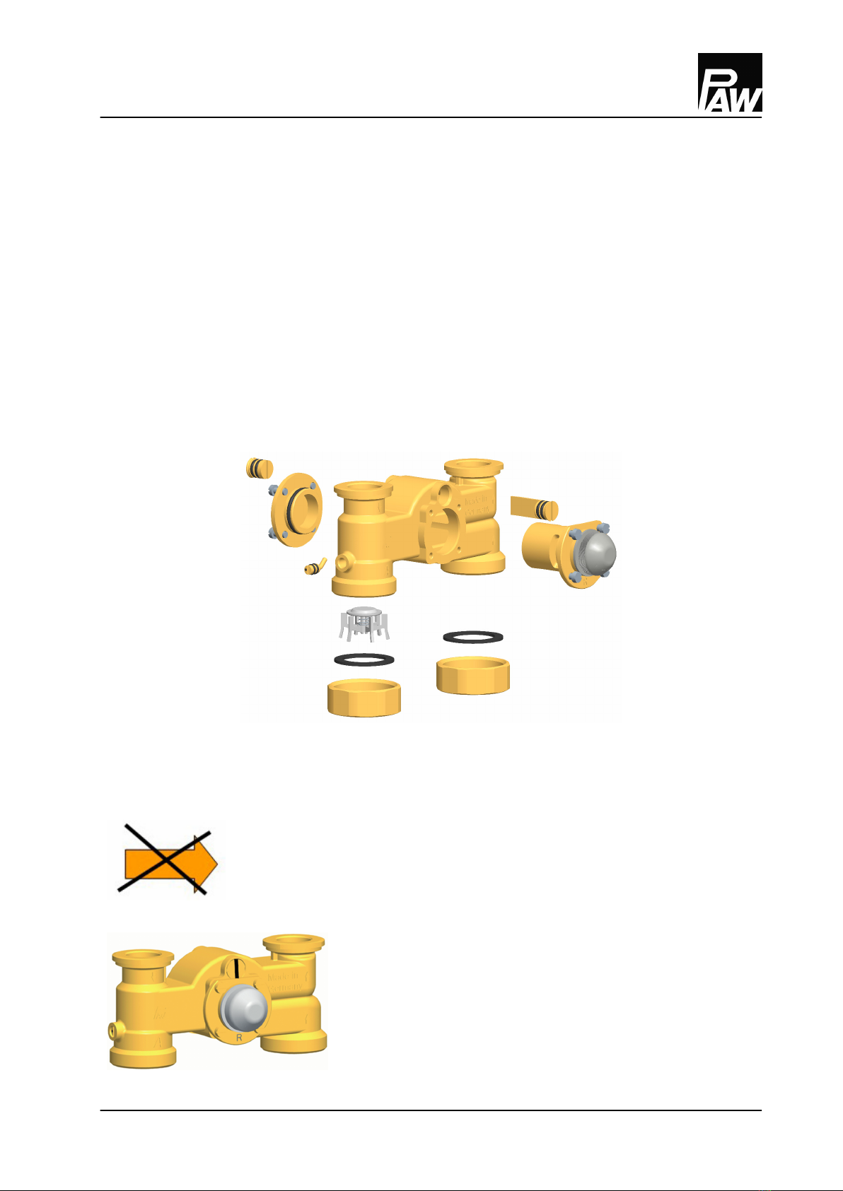
NOTICE
Damage to property!
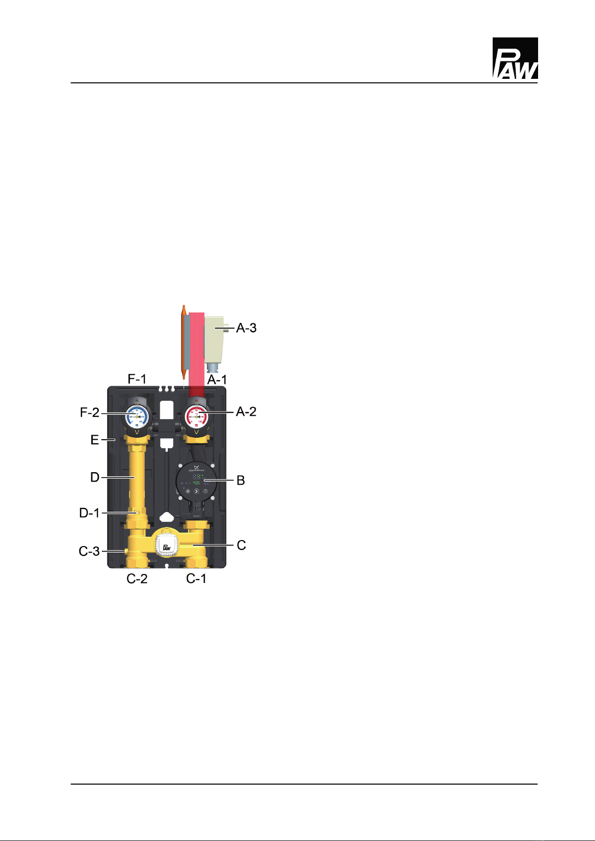
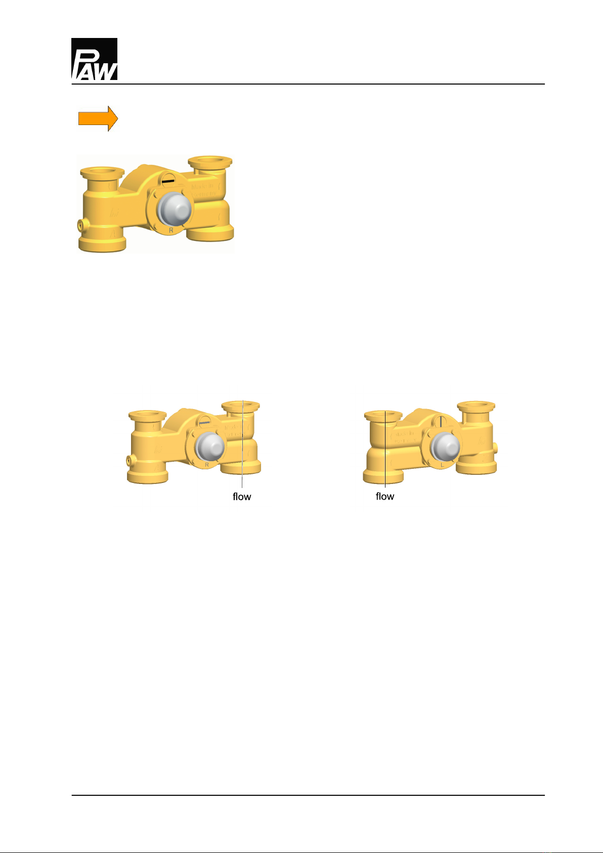
►It is mandatory to mount the contact thermostat at the flow.
Only in this way, it prevents the HeatBloC® from overheating.
2 Safety instructions
4 9936073x-mub-en - V04 08/2023

3 Product description
The HeatBloC® K33 is a preassembled group of fittings for heating circuits. The integrated pump can
be isolated by means of the ball valves and the mixing valve and can thus be maintained without
draining of the system.
The PAW HeatBloC® is directly mounted onto a PAW distribution manifold or a mounting plate.
With transition connections, PAW HeatBloC®s can also be mounted on PAW modular distribution
manifolds of other dimensions.
3.1 Equipment
A-1 Flow to the consumer circuit
A-2 All-metal thermometer with immersion sleeve,
integrated in the ball valve (flow)
A-3 Contact thermostat with contact sensor,
adjustable
B Heating pump
C 3-way mixing valve with adjustable bypass
0-50 %
C-1 Flow from the heat generator
C-2 Return to the heat generator
C-3 Non-return valve, can be opened
D Return pipe
D-1 Check valve, can be opened
E Design insulation with optimised function
F-1 Return from the consumer circuit
F-2 All-metal thermometer with immersion sleeve,
integrated in the ball valve (return)
3 Product description
08/2023 9936073x-mub-en - V04 5

3.2 Function
Controlled circuit with constant value 20-50 °C with
3‑way mixing valve and bypass 0-50%
The flow temperature of the heating circuit is controlled by
the integrated mixing valve. Hot water from the boiler and
cold return water are mixed to obtain the desired flow
temperature of the heating circuit. The flow temperature is
adjusted via the thermal mixing head and a flow contact
sensor.
Due to the premixing rate that must be adjusted at the
bypass of the mixing valve, a certain amount of cold return
water is added to the flow water. The 3-way actuator can
thus work over the whole adjustment range (closed ...
completely open).
Application range:
●Consumer circuits with a
considerably lower flow
temperature than the boiler
flow temperature
●Small heating circuits with low
output and low control
requirements
●Can be used instead of the
K32 if the existing controller
cannot actuate an additional
mixing valve.
Example: Panel heating systems operate on a low
temperature level with small temperature differences, but
with high flow rates. It is therefore sufficient to add a small
amount of hot water to the "warm" return water.
3 Product description
6 9936073x-mub-en - V04 08/2023

3.2.1 3-way mixing valve with bypass [specialist]
The 3-way mixing valve is a constant-value mixing valve for radiant panel heating systems (radiant
floor heating, wall heating etc.) which are operated with a constant flow temperature and thus
guarantee a basic heat supply. The desired flow temperature can be adjusted at the thermostatic
head.
The mixing valve is equipped with a bypass which must be operated separately. Via this bypass, cold
return water is added to the flow of the HeatBloC®. This can result in an increase of the flow rate of the
HeatBloC®.
Notice
When the heating circuit is delivered, the bypass is closed.
1. During commissioning, determine the optimum bypass position for the operation of the
installation. Find out and check the correct adjustment through a trial-and-error process.
If the slot of the bypass screw is in a vertical position, the bypass
is closed (normal operation).
3 Product description
08/2023 9936073x-mub-en - V04 7

If the slot of the bypass screw is in a horizontal position, the
bypass is completely open. A maximum flow rate from the
return to the flow line is thus enabled. This adjustment may be
necessary for radiant floor heating systems which require a very
high water flow volume. Because of the bypass, the flow
temperature decreases and the control may be affected in a
negative manner.
2. Check the position of the bypass during operation. Make sure that the flow rate is sufficient and
that the desired temperature is reached.
Change of the flow line
The HeatBloC® is available in two versions: with "flow on the right" and "flow on the left".
Mixing valve with flow on the right Mixing valve with flow on the left
3 Product description
8 9936073x-mub-en - V04 08/2023

WARNING
Malfunction!
To change the flow line, a conversion kit for the mixing valve is mandatory!
A retrofitting without conversion kit leads to a malfunction of the mixing valve.
Please specify the following information when ordering the conversion kit:
●Nominal diameter of the group of fittings (see designation of the pump)
●PAW item number or PAW designation
●Change from/to:
"for conversion from flow on the right to flow on the left" or
"for conversion from flow on the left to flow on the right"
Proceeding:
1. Take off the thermometer handles (A-2, F-2) and remove the insulating front shell.
2. Take the group of fittings out of the insulating back shell.
3. Dismount the mixing valve (C) and assemble it as described in the instructions of the conversion
kit.
4. Interchange the return pipe (D) and the flow pipe with the pump (B).
Consider the flow direction of the pump!
Turn the pump head such that the terminal box is directed to the top or to the centre of the
group of fittings.
5. Dismount and interchange the ball valves.
6. Mount the HeatBloC® and connect it to the installation.
7. Check all union nuts before commissioning and firmly tighten them if necessary.
8. Mount the insulation only after having carried out a pressure test. Mount the thermometer
handles (A-2, F-2) in a final step.
3 Product description
08/2023 9936073x-mub-en - V04 9

3.2.2 Check valve and non-return valve
The product is equipped with a check valve and with a non-return valve. The valves can be opened.
operation
During operation, the markings must point to "Z".
●The check valve and the non-return valve are
closed.
●Flow only in the direction of the arrow.
filling, draining, venting
For filling, draining and venting, the markings must
be directed to "A".
●The check valve and the non-return valve are
closed.
●Flow in both directions.
3 Product description
10 9936073x-mub-en - V04 08/2023

4 Mounting and installation [specialist]
The HeatBloC® can either be mounted on a distribution manifold or on a wall bracket. The distribution
manifold and the wall bracket are opt. accessories and are thus not included in the scope of delivery.
NOTICE
Damage to property!
The installation site must be dry, stable, frost-proof and protected against ultraviolet radiation in
order to prevent material damage of the installation.
4.1 Installation and commissioning of the HeatBloC®
The HeatBloC® can be mounted
Option 1:
on a PAW modular distribution manifold.
Option 2:
on a mounting plate.
consumer circuit
return flow
flow return
heat generator
consumer circuit
return flow
return flow
heat generator
4 Mounting and installation [specialist]
08/2023 9936073x-mub-en - V04 11

Option 3:
directly on a wall bracket.
Please observe the separate and respectively corresponding instructions regarding the installation of
the distribution manifold, of the mounting plate and of the wall bracket.
4 Mounting and installation [specialist]
12 9936073x-mub-en - V04 08/2023

1. Take off the thermometer handles (A-2, F-2)
and remove the insulating front shell of the
HeatBloC®.
2. Unscrew the nuts on the lower connections
of the HeatBloC® and take out the sealing
rings.
If a PAW modular distribution manifold or
transition connection is used:
3. Put the two nuts over the flanges.
4. Insert the sealing rings into the nuts.
5. Put the HeatBloC® onto the two nuts.
6. Tighten the nuts. Make sure that the nuts
do not get jammed and that the sealing
rings do not slip.
7. Connect the HeatBloC® to the installation
by using the pipes. The installation to the
piping must be carried out without any
tension.
8. Connect the pump.
9. Mount the contact thermostat and the
contact sensor (A-3) at the flow.
10. Carry out a pressure test and check all
thread connections.
11. Mount the insulating front shell and the
thermometer handles (A-2, F-2).
4 Mounting and installation [specialist]
08/2023 9936073x-mub-en - V04 13

4.2 Accessories: Cutting-ring compression fitting (not included in the scope of delivery)
The connection to the heating installation can be carried out fast, pressure-proof and without
soldering if you use the optionally available compression fittings.
1. Push the union nut ②and the cutting ring ③
onto the copper pipe ①. The pipe must protrude
at least 3 mm from the cutting ring in order to
ensure the force transmission and the sealing.
2. Insert the support sleeve ④into the copper pipe.
3. Insert the copper pipe with the plugged-on
individual parts ②, ③and ④as far as possible
into the body of the compression fitting ⑤.
4. First, screw the union nut ②manually.
5. Tighten the union nut ②by rotating one full
turn. Secure the body of the compression fitting
⑤against distort in order to avoid damaging the
sealing ring.
Not included in the scope of delivery!
4 Mounting and installation [specialist]
14 9936073x-mub-en - V04 08/2023

5 Scope of delivery [specialist]
NOTICE
Serial number
Complaints and requests/orders of spare parts will only be processed with information on the serial
number! The serial number is placed on the return pipe of the product.
5 Scope of delivery [specialist]
08/2023 9936073x-mub-en - V04 15

Position Spare part Item number
1 Thermometer ball valve DN 25, flange 1" x 1" int. thread N00244
2 Thermometer handle for thermometer ball valve 1" N00248
3 Dial thermometer, red scale, d = 50 mm, 0-120 °C N00242
4 Dial thermometer, blue scale, d = 50 mm, 0-120 °C N00243
5 Union nut G 1½" 2155
6 Gasket 1" for threaded connection 1½" N00131
7 Pump see following table
8 Insulation for HeatBloC® DN 25 N00016
9 Thermostatic head 20-50 °C, with contact sensor N00042
10 Brass pipe DN 25, 2 x 1½" ext. thread, 180 mm, with check valve N00018
11 Contact thermostat, 20-60 °C N00083
no pos. Sealing set for mixing valve 37013
no pos. Conversion kit for 3-way mixing valve "from flow on the left to flow
on the right"
340711
no pos. Conversion kit for 3-way mixing valve "from flow on the right to flow
on the left"
340722
Item no. heating circuit Pump Item no. pump EEI
36073WP6 Wilo Para SC 25/6-43 N00259 < 0.20
36073WP8 Wilo Para SC 25/8-60/O N00271 < 0.20
36073WN06 Wilo Yonos PICO 25/1-6 N00214 < 0.20
36073GL9 Grundfos UPML 25-105 Auto N00396 < 0.23
36073GM6 Grundfos UPM3 Auto L 25-70 PP3 N00237 < 0.20
36073GH6 Grundfos Alpha2.1 25-60 N00236 < 0.17
5 Scope of delivery [specialist]
16 9936073x-mub-en - V04 08/2023

6 Technical data
HeatBloC® K33 DN 25 (1")
Dimensions
Centre distance (1) 125 mm
Width insulation (2) 250 mm
Height insulation (3) 383 mm
Installation length (4) 340 mm
Connections
Outlet (A-1, F-1) 1" internal thread
Inlet (C-1, C-2) 1½" external threads, flat-sealing
Operating data
Max. pressure 6 bars
Max. temperature 110 °C
KVS value [m3/h] 3.0
Opening pressure check valve (D-1) 200 mm wc, can be opened
Opening pressure non-return valve (C-3) 50 mm wc, can be opened
6 Technical data
08/2023 9936073x-mub-en - V04 17

HeatBloC® K33 DN 25 (1")
Materials
Valves and fittings Brass
Gaskets EPDM
Insulation EPP
6.1 Pressure drop and pump characteristic curves
6 Technical data
18 9936073x-mub-en - V04 08/2023

7 Disposal
NOTICE
Electrical and electronic devices must not be disposed of in the household waste.
For your return, there are free collection points for electrical appliances and, if
necessary, additional points of acceptance for the reuse of the devices in your area.
The addresses can be obtained from your city or communal administration.
If the old electrical or electronic device contains personal data, you are responsible
for deleting it before returning the device.
Batteries and rechargeable batteries must be removed prior to the disposal of the
product. Depending on the product equipment (partly with optional accessories),
single components can also contain batteries and rechargeable batteries.
Please observe the disposal symbols on the components.
Disposal of transport and packaging materials
The packaging materials are made of recyclable materials and can be disposed of with recyclable
materials.
7 Disposal
08/2023 9936073x-mub-en - V04 19

Item no. 9936073x-mub-en
Translation of the original instructions
We reserve the right to make technical changes without
notice!
Printed in Germany – Copyright by PAW GmbH & Co. KG
PAW GmbH & Co. KG
Böcklerstraße 11
31789 Hameln, Germany
www.paw.eu
Phone: +49-5151-9856-0
Fax: +49-5151-9856-98
08/2023 9936073x-mub-en - V04
Other manuals for HeatBloC K33
2
Table of contents
Other PAW Control System manuals
Popular Control System manuals by other brands

Valeo
Valeo SC600 Indien operating instructions

Exhausto
Exhausto VEX200 series Basic instructions

ActronControls
ActronControls Leasam BM2-7D-4Z operating instructions

Eaton
Eaton COOPER POWER SERIES Installation and operation instructions

Parklio
Parklio Barrier user manual

Norac
Norac UC5 Topcon X30 installation manual