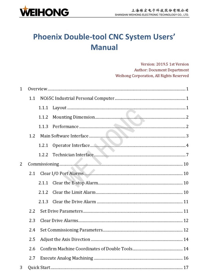
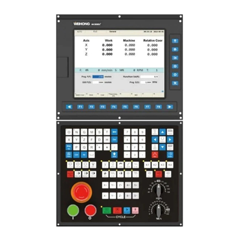
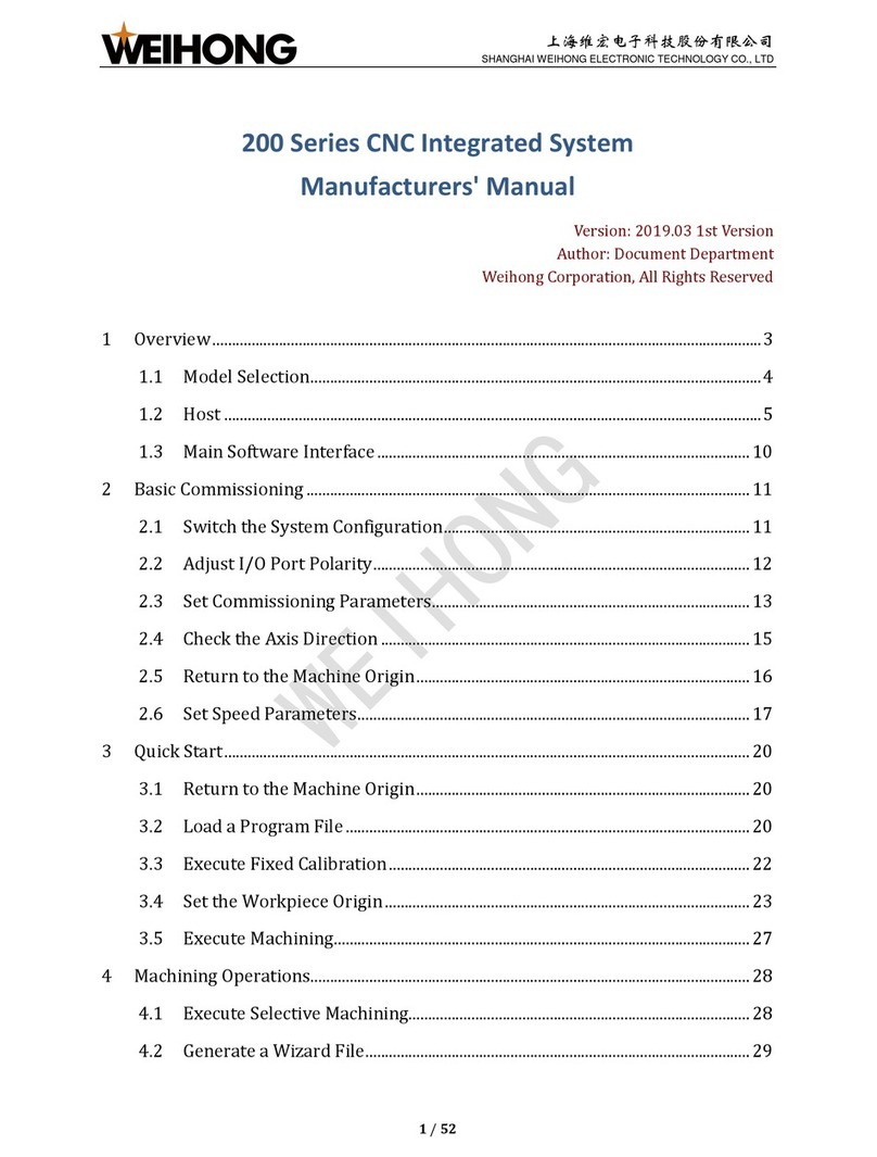
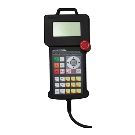
WEIHONG Ncstudio V15 User manual

上海维宏电子科技股份有限公司
SHANGHAI WEIHONG ELECTRONIC TECHNOLOGY CO., LTD.
Manufacturer's Manual of Ncstudio V15 Laser
Cutting (LS6000M) Control System
Version: 2022.01.14 2nd Version
Author: Product Testing Department
Weihong Corporation All Rights Reserved
Contents
1 Quick Start........................................................................................................................1
1.1 Overview....................................................................................................................1
1.2 Hardware Connection Diagram..................................................................................1
1.3 Shortcut Keys.............................................................................................................3
2 Install the System .............................................................................................................4
2.1 Overview....................................................................................................................4
2.2 Install Follow-up Amplifier ..........................................................................................4
2.3 Install Motion Control Card.........................................................................................4
2.4 Install the Software.....................................................................................................4
2.5 Install the Drive...........................................................................................................5
2.5.1 Automatic Installation...........................................................................................5
2.5.2 Manual Installation...............................................................................................6
3 System Debugging............................................................................................................7
3.1 Overview....................................................................................................................7
3.2 Configure Settings in NcConfig ..................................................................................7
3.2.1 Data Backup........................................................................................................8
3.2.2 Data Restoration..................................................................................................8
3.2.3 Device and Port Mapping Configuration..............................................................8
3.2.4 Port Protection.....................................................................................................9
3.3 Modify I/O Port Polarity ............................................................................................10
3.4 Set Drive Parameters...............................................................................................10
3.4.1 Set Drive Parameters in Non-bus Control Systems...........................................11
3.4.2 Set Drive Parameters in Bus Control Systems..................................................29
3.5 Set Bus System Parameters....................................................................................32
3.6 Set Speed Parameters.............................................................................................32
3.7 Set Pulse Equivalent................................................................................................33
3.8 Check Axis Direction................................................................................................34
3.9 Set Workbench Travel Limits ...................................................................................34
3.10 Set the Screw Error Compensation........................................................................34
3.10.1 Set the Backlash Compensation......................................................................35
3.10.2 Set the Bidirectional Compensation.................................................................35

上海维宏电子科技股份有限公司
SHANGHAI WEIHONG ELECTRONIC TECHNOLOGY CO., LTD.
3.11 Check Machine Settings.........................................................................................37
3.11.1 Pulse Equivalent and Electronic Gear Ratio....................................................37
3.11.2 Pulse................................................................................................................37
3.11.3 Laser Technic Settings ....................................................................................38
3.12 Do a Burn Test.......................................................................................................38
3.13 Install and Use the Camera....................................................................................39
3.13.1 Modify the Computer IP Address.....................................................................39
3.13.2 Modify the Camera IP Address........................................................................40
4 Follow Debugging...........................................................................................................42
4.1 Overview..................................................................................................................42
4.1.1 Tab Area............................................................................................................42
4.1.2 Coordinate Area.................................................................................................42
4.1.3 Manual Control Area..........................................................................................43
4.1.4 Follow Control Buttons.......................................................................................43
4.1.5 Follow Control Area/Follow Parameter Setting Area..........................................44
4.2 Operations................................................................................................................47
4.2.1 Prepare..............................................................................................................47
4.2.2 Measure the Capacitance..................................................................................48
4.2.3 Execute Servo Calibration.................................................................................48
4.2.4 Execute Calibration............................................................................................48
4.2.5 Check the Follow Function.................................................................................49
4.3 Follow Parameter.....................................................................................................49
4.3.1 System Setting...................................................................................................50
4.3.2 Follow Setting....................................................................................................50
4.3.3 Follow-up...........................................................................................................51
4.3.4 Calibrate Setting................................................................................................52
4.3.5 Speed Setting....................................................................................................53
4.3.6 Real-time State Check.......................................................................................54
4.3.7 Manual Speed....................................................................................................54
4.4 Common Problems...................................................................................................54
4.4.1 Serious Electric Interference..............................................................................55
4.4.2 Capacitance is Not Zero when Touching the Material .......................................55
4.4.3 Cutter Continues Lowering After Touching the Material During Calibration.......55
4.4.4 Actual Follow Height Differs from Setting ..........................................................55
4.4.5 Cutter Stops Working Frequently when Capacitance Feedback and Calibration
Results are Normal.....................................................................................................56
4.4.6 Cutter Has Severe Jitters When Cutting Thin Plates and Causing Workpiece
Outline Deformation....................................................................................................56
4.4.7 System Reports Follow Error when Moving Z axis or Enable Follow.................56
4.4.8 Encoder Direction or Axis Direction Error ..........................................................56
4.4.9 Follow In-position Waiting Timeout....................................................................57
4.4.10 Large Follow Error Alarm.................................................................................57
4.4.11 System Reports Material Collision Alarm when Follow is Enabled in Idle Status
or During Machining....................................................................................................57
4.4.12 System Reports Material Collision Alarm when the System Has No Movement
....................................................................................................................................58
4.4.13 Follow Overshoot.............................................................................................58
5 Wiring..............................................................................................................................59
5.1 Controller and Terminal Board .................................................................................59
5.1.1 Lambda Controller.............................................................................................59
上海维宏电子科技股份有限公司
SHANGHAI WEIHONG ELECTRONIC TECHNOLOGY CO., LTD.
5.1.2 Extension Terminal Board .................................................................................61
5.2 Laser........................................................................................................................63
5.2.1 IPG-YLR Series Laser.......................................................................................64
5.2.2 Feibo MARS-500W Laser..................................................................................64
5.2.3 Raycus Fiber Laser............................................................................................65
5.2.4 JK / GSI-500W-FL Laser ...................................................................................65
5.2.5 MAX Fiber Laser................................................................................................66
5.2.6 SPI-500W-R4 Laser...........................................................................................67
5.2.7 HFB 1000-1500W Laser....................................................................................67
5.2.8 GW SMATLas 3S Laser ....................................................................................68
5.3 Wiring Diagram of the Drive .....................................................................................69
5.3.1 Drive Port Definition...........................................................................................69
5.3.2 Wiring Diagram of the Drive (in Position Control Mode) ....................................71
5.3.3 Wiring Diagram of the Drive (in Velocity Control Mode).....................................92
6 Wireless Handwheel.....................................................................................................108
6.1 WHB05L(V4)..........................................................................................................108
6.2 WHB05L(V5)..........................................................................................................110
6.3 WHB05N(V1) .........................................................................................................113
6.4 Specifications.........................................................................................................115
6.5 Precautions............................................................................................................115
6.6 FAQs......................................................................................................................115
Legal Notices...................................................................................................................116
Requirements of Use....................................................................................................116
Intellectual Property Rights Notice ...............................................................................116
Termination..................................................................................................................116

上海维宏电子科技股份有限公司
SHANGHAI WEIHONG ELECTRONIC TECHNOLOGY CO., LTD.
1/ 116
1 Quick Start
1.1 Overview
This section introduces the hardware and software of the NcStudio V15 laser cutting
control system.
Hardware
oPM95A motion control card
oLambda controller
Non-bus control systems: Lambda 5E controller
Bus control systems: Lambda NE controller
oEX33A extension terminal board (for follow control)
oEX31A extension terminal board (for extension of terminal board ports)
oSE001 follow-up amplifier
oDB9M/F communication cables * 2
oRF cable * 1
oM16 three-core aviation plug towline cable * 1
oWHB05L wireless handwheel / WHB05N wireless handwheel
For hardware connection diagram, see Hardware Connection Diagram.
Software
For introduction of the software interface of the NcStudio V15 laser cutting
control system, see introduction of the software interface.
1.2 Hardware Connection Diagram
The connection method varies based on the control system type.
Non-bus control systems
The connection diagram is shown below:

上海维宏电子科技股份有限公司
SHANGHAI WEIHONG ELECTRONIC TECHNOLOGY CO., LTD.
2/ 116
Bus control systems
The connection diagram is shown below:

上海维宏电子科技股份有限公司
SHANGHAI WEIHONG ELECTRONIC TECHNOLOGY CO., LTD.
3/ 116
1.3 Shortcut Keys
The shortcut keys are as follows:

上海维宏电子科技股份有限公司
SHANGHAI WEIHONG ELECTRONIC TECHNOLOGY CO., LTD.
4/ 116
2 Install the System
2.1 Overview
This section gives an overview of system installation.
2.2 Install Follow-up Amplifier
During installation of the follow-up amplifier, the external metal part of the amplifier contact
side needs to be installed correctly on the machine to shield signal interference effectively.
Install the follow-up amplifier as shown below:
2.3 Install Motion Control Card
PM95A motion control card is used together with the NcStudio motion control software for
a fast and accurate control of laser cutting movement.
Before installing the motion control card, ensure that:
CPU: >1G
RAM: >1G
Hard drive: >20G
Video card
Display: ≥ 14VGA
Motherboard extension slot: PCI-E slot ≥ 1
The PM95A motion control card needs to be installed on the computer.
Follow the steps below to install the PM95A control card:
1. Turn off the computer power supply and open the mainframe cover.
2. Gently press the two sides of the control card to secure it in the PCI-E slot.
3. Fix the control card screws and close the mainframe cover.
4. Restart the computer.
If the control card is installed, and Install the Drive is successful, but the NcStudio
software cannot run normally, turn off the computer and check to see if the gold fingers are
clean:
Yes: Clean them with an eraser.
No: Replace the control card.
2.4 Install the Software
This section introduces how to install the software of the NcStudio V15 laser cutting
control system.

上海维宏电子科技股份有限公司
SHANGHAI WEIHONG ELECTRONIC TECHNOLOGY CO., LTD.
5/ 116
Before installing the software, ensure that:
The computer has a disk D.
If it is the first time that you install the software on the computer, ensure that the
basic environment package PhoenixEnvironmentsBeta1.msi is already installed.
Copy the software installation package to the computer and follow the steps below to
install the software:
1. Decompress the installation package and double-click . An installation wizard
window will be displayed.
2. Select the installation language and click OK > Next.
3. Select the target configuration: bus or non-bus configuration. Click Next.
4. Select whether to keep certain parameter settings and click Next.
5. Finish the installation.
The installation program will prompt you to Install the Drive.
To uninstall the software, follow the steps below:
1. Delete the NcStudio folder under C:\Program Files\Weihong.
2. Delete the NcStudio shortcut on the desktop.
2.5 Install the Drive
The corresponding drive matching the software and hardware needs to be installed to
install the NcStudio V15 laser cutting control system.
The system will perform Automatic Installation during software installation process. If the
automation fails, you need to Manual Installation.
2.5.1 Automatic Installation
Taking a Win7 system as an example, after the software is installed, the system will
display a Windows security dialog box, asking whether you would like to install the device
software. Continue installation.

上海维宏电子科技股份有限公司
SHANGHAI WEIHONG ELECTRONIC TECHNOLOGY CO., LTD.
6/ 116
After the drive is installed, the system will prompt you for a restart, which means the drive
has been installed successfully.
2.5.2 Manual Installation
After installation of the motion control card and software, if the software cannot open, the
automatic installation of the drive may have failed. After ruling out the possibilities such as
poor contact of the control card, install the drive manually.
Taking a Win7 system as an example, follow the steps below to manually install the drive:
1. Right-click on Computer, click Manage:
oFirst-time manual drive update: In the left list, click Device Manager. Go to
Action > Scan for hardware changes in the menu bar or click the Scan for
hardware changes icon under the menu bar. In the right list under Other
devices, click the network and computer encryption and decryption controller
option.
oNon-first manual drive update: In the left list, click Device Manager. In the
right list under motion controller, click the WEIHONG motion controller (PM
series) option.
2. Follow the steps below to find the INF configuration file:
a. In the displayed dialog box, browse the computer to find the drive program.
b. Click the option of selecting from the computer device program list.
c. Click Install From Disk. The Install From Disk dialog box is displayed.
d. Click Browse.
e. In the file searching dialog box, find the file and click Open.
The file storage path is C:\Program
Files\Weihong\NcStudio\Bin\DriverCH365.
3. In the displayed Windows security dialog box, click Install.
After installing the drive manually, restart the system as prompted.

上海维宏电子科技股份有限公司
SHANGHAI WEIHONG ELECTRONIC TECHNOLOGY CO., LTD.
7/ 116
3 System Debugging
3.1 Overview
This section gives an overview of the debugging process for the NcStudio V15 laser
cutting control system:
3.2 Configure Settings in NcConfig
The offline configuration tool NcConfig can be used to backup/restore data, configure
devices, and map/protect the ports to improve project development efficiency.
Follow the steps below the configure settings in NcConfig:
1. Open the Ncstudio installation path C:\Program
Files\Weihong\NcStudio\NcConfig\Bin. Find and double-click NcConfig.exe.
2. Use the following functions based on your needs:
oData Backup

上海维宏电子科技股份有限公司
SHANGHAI WEIHONG ELECTRONIC TECHNOLOGY CO., LTD.
8/ 116
oData Restoration
oDevice and Port Mapping Configuration
oPort Protection
3.2.1 Data Backup
Follow the steps below to use NcConfig to back data:
1. In the menu bar, go to Systems > Backup and Restore.
2. In the Backup and Restore Data window, select Backup Data. Click Next.
3. Edit the backup file name and storage path as needed.
4. Click Finish.
3.2.2 Data Restoration
If data is lost due to incorrect operation, you can use NcConfig to restore data. If system
environment data is lost due to system damage, you can use the installation package and
the data restoration function to recover the system.
Before restoring the data, ensure that the data was backed up as described in Data
Backup.
Follow the steps below to restore data in NcConfig:
1. In the menu bar, go to Systems > Backup and Restore.
2. In the Backup and Restore Data window, select Data Restore. Click Next.
3. Click Browse to select the backup file and the target data collection you want to
import.
4. Click Finish.
3.2.3 Device and Port Mapping Configuration
You can configure devices and modify port physical addresses to match their logical
addresses.
Follow the steps below to configure devices:
1. In the left Configuration column, go to NcStudio > Hardware Connection and
Configuration > Device Configuration.
2. Double-click Device Configuration to open the Device Configuration window to
the right:

上海维宏电子科技股份有限公司
SHANGHAI WEIHONG ELECTRONIC TECHNOLOGY CO., LTD.
9/ 116
3. Configure the devices based on your demands:
oTo add a controller/terminal board, right-click on BusO and select Add
controller and select the target controller/terminal board.
oTo replace a controller/terminal board, right-click on the controller/terminal
board to be replaced and click Replace. Select the target controller/terminal
board in the displayed list.
oTo delete a controller/terminal board, right-click on the controller/terminal
board to be deleted and click Delete.
oTo move a controller/terminal board, click the controller/terminal board to be
moved and click Up/Down.
4. Save the change by clicking or .
Follow the steps below to configure port mapping:
1. In the left column, click the Configuration tab. Go to NcStudio > Hardware
Connection and Configuration > Port Mapping.
2. Double-click Port Mapping to open the Port Mapping window to the right.
3. In the port list:
oTo show only a certain type of ports, click the category on the left, such as
Lubricate.
oTo modify the physical address of a logical address, double-click the
corresponding physical address box and select the target controller and port.
oTo show/hide the logical addresses, right-click on the Enter/Output list and
select Display logical address/Hide logical address.
oTo delete a port mapping, right-click on the Enter/Output list and select
Delete port mapping.
oTo delete invalid port mapping, right-click on the Enter/Output list and select
Delete invalid port mapping.
3.2.4 Port Protection
When the software is closed, the protected ports will be automatically closed, opened,
following the status of the specified port, or reversed based on their port protection type.
There are several types of port protection:
Open: The port will be automatically opened when the software is closed.
Closure: The port will be automatically closed when the software is closed.
Follow: The protected port status will be turned the same with that of the port
specified in the Follow port column.
Reverse: The protected port status will be turned the opposite to that of the port
specified in the Follow port column.
Follow the steps below to set port protection:
1. In the left Configuration list, double-click Port Protect to open the Port Protect
window to the right:

上海维宏电子科技股份有限公司
SHANGHAI WEIHONG ELECTRONIC TECHNOLOGY CO., LTD.
10 / 116
2. Select and click the Configuration type field of the target port and select a
protection type in the pull-down menu.
3. Select one from the following methods to save the changes:
oTo save changes on the current page, click under the menu bar.
oTo save changes on all open pages, click under the menu bar.
The * symbol on an open window tab indicates that the changes on the page have not
been saved. The * symbol disappears after changes on the page are saved.
3.3 Modify I/O Port Polarity
During debugging, you can modify the I/O port polarity based on your needs or to check to
see if the port input and output are normal.
Set the polarity of normally closed switches to NC. Set the polarity of normally open
switches to NO.
Follow the steps below to modify the I/O port polarity:
1. Click Monitor in the bottom function bar.
2. Click the Port Setting tab. Click the target port and click Convert to reverse its
current polarity. indicates no signal while indicates signals are detected.
3. The following functions are also supported:
oTo test port signal output: Click Test On/Test Off. When the port symbol
becomes or , the port is under test.
oTo cancel testing of the selected port: Click Cancel Test.
oTo cancel testing of all ports: Click Cancel All.
oTo set sampling interval, click Filter and drag the Interval slider. The system
will rule out signals whose duration is smaller than the interval.
3.4 Set Drive Parameters
Basic drive parameters need to be set before the drive can start driving machining
movement.

上海维宏电子科技股份有限公司
SHANGHAI WEIHONG ELECTRONIC TECHNOLOGY CO., LTD.
11 / 116
Different control systems require different settings.
Set Drive Parameters in Non-bus Control Systems
Set Drive Parameters in Bus Control Systems
3.4.1 Set Drive Parameters in Non-bus Control Systems
Different servo drive parameters need to be set in different follow control modes:
Set Drive Parameters in Position Loop Control Mode
Set Drive Parameters in Velocity Loop Control Mode
If you are using a non-WEIHONG drive (WISE):
Ensure that the servo drive SON signal is active low (ON when connected to GND
of a 24V power supply).
If the servo drive is active low when it works normally, set the polarity of the drive
alarm input port to NC. If the servo drive is active low when it reports an alarm, set
the polarity of the drive alarm input port to NO.
Set the drive pulse signal type parameter to pulse + direction.
Ensure that the servo drive does not have an external emergency stop signal input
port. If it does, check the signal logic.
Ensure that the terminal board is connected to a 24V power supply before drive trial
run.
3.4.1.1 Set Drive Parameters in Position Loop Control Mode
Test parameter settings in position loop control mode as shown below:
WISE
Yaskawa Σ-Ⅱ
Yaskawa Σ-ⅡΣ-Ⅴ/ Σ-7
Panasonic MINAS A4
Panasonic MINAS A5
Fuji FALDIC-β
Fuji ALPHA 5
Delta ASDA-A
Delta ASDA-A2
Delta ASDA-B
Delta ASDA-B2
3.4.1.1.1 WISE
The parameters and descriptions are shown below:
Pr001 Control mode selection
oDescription: Control mode setting
oUnit: -
oRange
1: Position control mode
2: Velocity control mode
oValue: 1
Pr528 LED initial state
oDescription: Pulse detection is used in WEIHONG control systems to check
to see if correct pulses are sent and determine if there is electric interference.
oUnit: -
oRange: -
oValue: 6 Command pulse sum
Pr008 Number of command pulses per motor turn

上海维宏电子科技股份有限公司
SHANGHAI WEIHONG ELECTRONIC TECHNOLOGY CO., LTD.
12 / 116
oDescription: The number of command pulses for the motor to rotate by one
turn
oUnit: -
oRange
0: Pr009 and Pr010 are effective
Not 0: Pr008 = Screw pitch/(pulse equivalent * mechanical
reduction ratio)
oValue: 0
Pr009 1st command division and multiplication (numerator), Pr010 Command
division and multiplication (denominator)
oDescription: Pay attention to the ratio between Pr009 and Pr010.
oUnit: -
oRange: 0–230
oValue: If screw pitch = 5 mm, encoder resolution = 10000, directly connected
to the coupler, pulse equivalent = 0.001 mm: Pr009 = 10000, Pr010=screw
pitch / pulse equivalent=5000, which means Pr009/Pr010 = 10000/5000=2/1.
Pr011 Number of pulses output by one motor turn
oDescription: Number of pulses output by one motor turn
oUnit: -
oRange: -
ovalue: If pulse equivalent = 0.001, there is no speed reducer, screw pitch =
10 mm: Pr011=2500; if screw pitch = 5 mm: Pr011 = 1250
Pr100 1st position loop gain
oDescription: 1st position loop gain
oUnit: 0.1/s
oRange: -
oValue: 480 (default) or subject to actual situation.
Pr101 1st velocity loop gain
oDescription: 1st velocity loop gain
oUnit: 0.1 Hz
oRange: -
oValue: 270 (default) or subject to actual situation.
Pr102 1st velocity loop integral time constant
oDescription:1st velocity loop integral time constant
oUnit: 0.1 ms
oRange: -
oValue: 210 (default) or subject to actual situation.
Relationship between Pr008, Pr009, and Pr010
Pr009 and Pr010 values are not valid. System processing is based on the Pr008
value.
If Pr008 and Pr009 are 0, system processing is based on the Pr010 value.

上海维宏电子科技股份有限公司
SHANGHAI WEIHONG ELECTRONIC TECHNOLOGY CO., LTD.
13 / 116
If Pr008 is 0, and Pr009 and Pr010 values are not valid:
3.4.1.1.2 Yaskawa Σ-Ⅱ
The parameters and descriptions are shown below:
Fn010 Password setting (preventing random parameter modification)
oDescription: Password setting (preventing random parameter modification)
oUnit: -
oRange
If Fn010 is set to 0000, modification of user parameters (PnXXX) and
some auxiliary function parameters (FnXXX) is allowed.
If Fn010 is set to 0001, modification of user parameters (PnXXX) and
some auxiliary function parameters (FnXXX) is not allowed.
oValue: 0000
Un00C Input command pulse counter
oDescription: Pulse detection is used in WEIHONG control systems to check
to see if correct pulses are sent and determine if there is electric interference.
oUnit: -
oRange: -
oValue: In hexadecimal, low-order (L) 4 digits
Pn000 Rotation direction and control mode selection
oDirection: Rotation direction and control mode selection
oUnit: -
oRange
0: The motor rotates CW (anti-clockwise when observing from the
load/lead screw side).
1: The motor rotates CCW. The control mode is position control.
Always calculates pulse commands.
oValue: 0010
Pn200 Pulse command format selection
oDescription: Pulse command format selection
oUnit: -
oRange
Digit 0: If digit 0 is set to 5, the command is pulse + direction, negative
logic.
Digit 3: If digit 3 is set to 0, the differential signal goes into the filter.
oValue: 0005

上海维宏电子科技股份有限公司
SHANGHAI WEIHONG ELECTRONIC TECHNOLOGY CO., LTD.
14 / 116
Pn50A Function selection
oDescription: Function selection
oUnit: -
oRange
Digit 1: If digit 1 is set to 0, the /S-ON signal is enabled and its input
pin is No.40. If digit 1 is set to 7, the /S-ON signal is always ON.
Digit 3: If digit 3 is set to 8, the CW input inhibition signal P-OT will not
be used.
oValue: 8100
Pn50B Function selection
oDescription: Function selection
oUnit: -
oRange: Digit 0: If digit 0 is set to 8, the CCW input inhibition signal N-OT will
not be used.
oValue: 6548
Pn50F Function selection
oDescription: Applicable when the servo motor has a brake.
oUnit: -
oRange: Digit 2: If digit 2 is set to 3, CN1-29 and 30 output brake interlocking
signal/BK to control the 24V relay for brake.
oValue: 0300
Pn50E Function selection
oDescription: Applicable when the servo motor has a brake.
oUnit: -
oRange: None of the four digits can be set to 3 in case that CN1-29 and CN1-
30 are used for other functions, causing braking failure.
oValue: 0211
Pn506 Brake delay when servo motor is off
oDescription: Applicable when the servo motor has a brake.
oUnit: 10 ms
oRange: -
oValue: Subject to actual situation.
Pn202 Electronic gear ratio numerator, Pn203 Electronic gear ratio
denominator
oDescription: Relation between Pn202 and Pn203
oUnit: 10 ms
oEquation:
Pn202 = Pulse number per encoder turn ×4 ×Mechanical
deceleration rate
Pn203 = Screw pitch/ Pulse equivalent
oRange: -
oValue
When screw pitch = 5 mm, the encoder is 17 digits, axis coupling joint
is used, pulse equivalent = 0.001 mm: Pn202=16384 and Pn203=
625
When screw pitch = 5 mm, the encoder is 17 digits, axis coupling joint
is used, pulse equivalent = 0.0005 mm: Pn202=8192 and Pn203=
625

上海维宏电子科技股份有限公司
SHANGHAI WEIHONG ELECTRONIC TECHNOLOGY CO., LTD.
15 / 116
3.4.1.1.3 Yaskawa Σ-Ⅴ/Σ-7
The parameters and descriptions are shown below:
Fn010 Parameter input inhibition setting
oDescription: Parameter input inhibition setting
oUnit: -
oRange
If Fn010 is set to 0000, modification of user parameters (PnXXX) and
some auxiliary function parameters (FnXXX) is allowed.
If Fn010 is set to 0001, modification of user parameters (PnXXX) and
some auxiliary function parameters (FnXXX) is not allowed.
oValue: 0000
Pn000 Function selection basic switch 0
oDescription: Function selection basic switch 0
oUnit: -
oRange
Digit 0: If digit 0 is set to 0, the motor rotates CW after receiving CW
commands.
Digit 1: If digit 1 is set to 1, the control mode is position control (pulse
sequence commands).
oValue: 0010
Pn200 Position control command format selection switch
oDescription: Position control command format selection switch
oUnit: -
oRange: If digit 0 is set to 5, the command format is pulse + direction,
negative logic.
oValue: 0005
Pn50A Input signal selection 1
oDescription: Input signal selection 1
oUnit: -
oRange
Digit 1: If digit 1 is set to 0, /S-ON signal is enabled and its input pin is
No.40. If digit 1 is set to 7, the servo drive is always ON.
Digit 3: If digit 3 is set to 8, the CW input inhibition signal P-OT will not
be used.
oValue: 8100
Pn50B Input signal selection 2
oDescription: Input signal selection 2
oUnit: -
oRange: If digit 0 is set to 8, the CCW input inhibition signal N-OT will not be
used.
oValue: 6548
Pn50F Output signal selection 2
oDescription: Applicable when the servo motor has a brake.
oUnit: -
oRange: If digit 2 is set to 3, CN1-29 and 30 output brake interlocking
signal/BK to control the 24V relay for brake.
oValue: 0300
Pn50E Output signal selection 1
oDescription: Applicable when the servo motor has a brake.

上海维宏电子科技股份有限公司
SHANGHAI WEIHONG ELECTRONIC TECHNOLOGY CO., LTD.
16 / 116
oUnit: -
oRange: None of the four digits can be set to 3 in case that CN1-29 and CN1-
30 are used for other functions, causing braking failure.
oValue: 0211
Pn506 Brake command: Servo OFF delay
oDescription: Applicable when the servo motor has a brake.
oUnit: ms
oRange: -
oValue: Subject to actual situation.
Pn20E Electronic gear ratio numerator, Pn210 Electronic gear ratio
denominator
oDescription: Relation between Pn20E and Pn210
oUnit: -
oEquation: Pn20E/Pn210 = (Encoder resolution ×pulse equivalent ×
mechanical reduction ratio)/screw pitch
oRange: -
oValue: Manual calculation
Pn212 Encoder allocated pulse number
oDescription: Encoder allocated pulse number
oUnit: -
oRange:24–230
oValue: When pulse equivalent = 0.001, there is no reducer, and screw pitch =
10 mm, Pn212 = 2500; when screw pitch = 5 mm, Pn212 = 1250
3.4.1.1.4 Panasonic MINAS A4
The parameters and descriptions are shown below:
Pr01 LED initial state
oDescription: Pulse detection is used in WEIHONG control systems to check
to see if correct pulses are sent and determine if there is electric interference.
oUnit: -
oRange: -
oValue: 15
Pr02 Control mode selection
oDescription: Control mode selection
oUnit: -
oRange
0: Position control
1: Velocity control
2: Torque control
oValue: 0
Pr40 Command pulse input selection
oDescription: Command pulse input selection
oUnit: -
oRange: 1: input via dedicated differential circuit.
oValue: 1
Pr42 Command pulse input format selection
oDescription: Command pulse input format selection
oUnit: -
oRange: 3: The command pulse input format is pulse + direction, negative
logic

上海维宏电子科技股份有限公司
SHANGHAI WEIHONG ELECTRONIC TECHNOLOGY CO., LTD.
17 / 116
oValue: 3
Pr44 Feedback pulse division and multiplication numerator
oDescription: Feedback pulse division and multiplication numerator
oUnit: -
oRange: 1–32767
oTypical value: When pulse equivalent = 0.001, there is no reducer, and
screw pitch = 10 mm, Pr44 = 2500; when screw pitch = 5 mm, Pr44 = 1250
Pr48 Command pulse division and multiplication 1st numerator, Pr4B
Command pulse division and multiplication denominator
oDescription: Relation between Pr48 and Pr4B
oUnit: -
oRange: 1–10000
oValue: When screw pitch = 5 mm, the encoder resolution is 10000, axis
coupling joint is used, and pulse equivalent = 0.001 mm: Pr48= 10000, Pr4B
=screw pitch/pulse equivalent = 5/0.001=5000. Pr48/Pr4B=10000/5000=2/1.
3.4.1.1.5 Panasonic MINAS A5
The parameters and descriptions are shown below:
Pr5.28 LED initial state
oDescription: Pulse detection is used in WEIHONG control systems to check
to see if correct pulses are sent and determine if there is electric interference.
oUnit: -
oRange: -
oValue: 6
Pr0.01 Control mode setting
oDescription: Control mode setting
oUnit: -
oRange
0: Position control.
1: Velocity control.
2: Torque control.
oValue: 0
Pr0.05 Command pulse input selection
oDescription: Command pulse input selection
oUnit: -
oRange
0: Opto-electronic coupler input (PULS1, PULS2, SIGN1, SIGN2)
1: Dedicated line drive input (PULSH1, PULSH2, SIGNH1, SIGNH2)
oValue: 1 (in common cases)
Pr0.07 Command pulse input format selection
oDescription: Command pulse input format selection
oUnit: -
oRange: 3: the command pulse input format is pulse + direction, negative
logic
oValue: 3
Pr0.08 Number of command pulses per turn
oDescription: Number of command pulses per turn
oUnit: -
oRange
If Pr0.08 is set to 0, Pr0.09 and Pr0.10 are valid.
This manual suits for next models
1
Table of contents
Other WEIHONG Control System manuals

WEIHONG
WEIHONG NC65C User manual

WEIHONG
WEIHONG NK200 User manual

WEIHONG
WEIHONG NCStudio V12 User manual

WEIHONG
WEIHONG NK280B User manual

WEIHONG
WEIHONG NK105 G2F User manual

WEIHONG
WEIHONG NK300CX User manual

WEIHONG
WEIHONG NK300CX User manual

WEIHONG
WEIHONG NK105 User manual

WEIHONG
WEIHONG NK280 User manual

WEIHONG
WEIHONG NcEditor V12 User manual
Popular Control System manuals by other brands

OPTIMUM Maschinen
OPTIMUM Maschinen OPTImill F 80 operating manual

Intermatic
Intermatic PF1112T Installation, operation & service manual

RTS
RTS DBP 4M Technical manual

Mitsubishi Electric
Mitsubishi Electric E70 Series instruction manual

Nibe
Nibe SMO S40 Installer manual

Meritor
Meritor TACTX HMIS Maintenance manual