manuals.online logo
Brands
  1. Home
  2. •
  3. Brands
  4. •
  5. CAME
  6. •
  7. Control System
  8. •
  9. CAME G5000 User manual

CAME G5000 User manual

Other CAME Control System manuals

CAME RBM84-HW User manual

CAME

CAME RBM84-HW User manual

CAME GARD 4 SERIES User manual

CAME

CAME GARD 4 SERIES User manual

CAME GARD PT Brushless User manual

CAME

CAME GARD PT Brushless User manual

CAME ACS-EM User manual

CAME

CAME ACS-EM User manual

CAME PS ONE User manual

CAME

CAME PS ONE User manual

CAME GARD G3250 User manual

CAME

CAME GARD G3250 User manual

CAME 806SA-0010 User manual

CAME

CAME 806SA-0010 User manual

CAME GARD 8 SERIES Owner's manual

CAME

CAME GARD 8 SERIES Owner's manual

CAME GARD G3250 User manual

CAME

CAME GARD G3250 User manual

CAME GARD 8 SERIES User manual

CAME

CAME GARD 8 SERIES User manual

CAME G4040Z User manual

CAME

CAME G4040Z User manual

CAME 806SA-0040 User manual

CAME

CAME 806SA-0040 User manual

CAME GARD series User manual

CAME

CAME GARD series User manual

CAME PST001 User manual

CAME

CAME PST001 User manual

CAME g2500 User manual

CAME

CAME g2500 User manual

CAME GARD series User manual

CAME

CAME GARD series User manual

CAME ACS01 User manual

CAME

CAME ACS01 User manual

CAME DIR10 User manual

CAME

CAME DIR10 User manual

CAME GARD PT Brushless User manual

CAME

CAME GARD PT Brushless User manual

CAME Z Series User manual

CAME

CAME Z Series User manual

CAME FA01584M4A User manual

CAME

CAME FA01584M4A User manual

CAME CAT Series User manual

CAME

CAME CAT Series User manual

CAME ZCX10 User manual

CAME

CAME ZCX10 User manual

CAME PS ONE SERIES User manual

CAME

CAME PS ONE SERIES User manual

Popular Control System manuals by other brands

Comunello BORDER 400 Installation and user manual

Comunello

Comunello BORDER 400 Installation and user manual

Verlinde EUROBLOC Variator VTN Service manual

Verlinde

Verlinde EUROBLOC Variator VTN Service manual

Diginet DGOZ-TCSW-LR35 installation guide

Diginet

Diginet DGOZ-TCSW-LR35 installation guide

VADDIO ControlVIEW Xtreme manual

VADDIO

VADDIO ControlVIEW Xtreme manual

Duke HSHU 13 SERIES Installation and operation manual

Duke

Duke HSHU 13 SERIES Installation and operation manual

AIRTRONICS Blazer Sport manual

AIRTRONICS

AIRTRONICS Blazer Sport manual

Pentair Pool Products Compool Installation and user guide

Pentair Pool Products

Pentair Pool Products Compool Installation and user guide

ComfortNET CTK04 manual

ComfortNET

ComfortNET CTK04 manual

Idemia MorphoAccess VP MD installation guide

Idemia

Idemia MorphoAccess VP MD installation guide

Doosan DVF Series Operation user's manual

Doosan

Doosan DVF Series Operation user's manual

Axis P1445-LE-3 user manual

Axis

Axis P1445-LE-3 user manual

CNC-Step High-Z T-Series operating instructions

CNC-Step

CNC-Step High-Z T-Series operating instructions

Honeywell KAP 140 Maintenance manual

Honeywell

Honeywell KAP 140 Maintenance manual

Honeywell vk41 series Handbook

Honeywell

Honeywell vk41 series Handbook

Cypress HHR-3160 product manual

Cypress

Cypress HHR-3160 product manual

Zonex GEN II -VVT Installation and application manual

Zonex

Zonex GEN II -VVT Installation and application manual

Altronics K 9650 quick start guide

Altronics

Altronics K 9650 quick start guide

micro-trak RoadMaster Reference manual

micro-trak

micro-trak RoadMaster Reference manual

manuals.online logo
manuals.online logoBrands
  • About & Mission
  • Contact us
  • Privacy Policy
  • Terms and Conditions

Copyright 2025 Manuals.Online. All Rights Reserved.

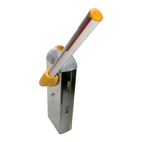
Automatic barrier
- GARD series
G5000
INSTALLATION OPERATION AND MAINTENANCE MANUAL En
g
lish
FA00571-EN
p. 2- Manual FA00571-EN v. 1- 08/2017- © CAME S.p.A. - The contents of this manual may be changed, at any time, and without notice.
CAME
CAME
G5000
p. 3- Manual FA00571-EN v. 1- 08/2017- © CAME S.p.A. - The contents of this manual may be changed, at any time, and without notice.
GENERAL PRECAUTIONS FOR INSTALLERS
⚠CAUTION! Important safety instructions.
Carefully follow these instructions for the safety of people.
Keep these instructions.
BEFORE USING THIS PRODUCT, READ ALL ITS SAFETY PRECAUTIONS • THIS PRODUCT SHOULD ONLY BE USED FOR THE PURPOSE FOR WHICH IT WAS EXPLICITLY DESIGNED.
ANY OTHER USE IS DANGEROUS. CAME S.P.A. IS NOT LIABLE FOR ANY DAMAGE CAUSED BY IMPROPER, WRONGFUL AND UNREASONABLE USE. • THIS PRODUCT SUPPLIED
BY CAME S.P.A. IS CONSIDERED TO BE "PARTLY-COMPLETED MACHINERY", PURSUANT TO MACHINERY DIRECTIVE 2006/42/CE. PARTLY-COMPLETED MACHINERY
IS AN ASSEMBLY THAT ALMOST CONSTITUTES AMACHINE, BUT WHICH, ALONE, CANNOT ENSURE ACLEARLY DEFINED APPLICATION. PARTLY-COMPLETED MACHINERY IS
ONLY DESTINED TO BE INCORPORATED OR ASSEMBLED TO OTHER MACHINERY OR OTHER PARTLY-COMPLETED MACHINES OR APPARATUSES TO BUILD AMACHINE REGULATED
BY DIRECTIVE 2006/42/CE. THE FINAL INSTALLATION MUST BE COMPLIANT WITH EUROPEAN DIRECTIVE 2006/42/CE AND EUROPEAN REFERENCE STANDARDS:
EN 13241-1, EN 12453, EN 12445 AND EN 12635 • IFTHE BARRIER IS ONLY FOR REGULATING VEHICLE PASSAGES YOU MUST INSTALL APEDESTRIAN
PASSAGEWAY NEAR THE OPERATOR ITSELF. SUITABLE SIGNS MUST BE AFFIXED AND CLEARLY VISIBLE TO WARN PEDESTRIANS IT IS FORBIDDEN TO TRANSIT THROUGH THE
DRIVEWAY. IFTHE BARRIER IS FOR BOTH VEHICLES AND PEDESTRIANS, CARE MUST STILL BE EXERCISED WHEN TRANSITING THROUGH THE APERTURE. DRIVE OR WALK
THROUGH THE OPENING WHEN THE BARRIER IS STOPPED AND ENTIRELY RAISED AND AS FAR AS POSSIBLE FROM THE ROTATING FULCRUM OF THE BOOM • ALL SYSTEM
SETTING UP AND OPERATOR INSTALLATION TASKS MUST BE CONDUCTED EXCLUSIVELY BY QUALIFIED, EXPERT STAFF • ANIN-DEPTH REPORT ON ANY RESIDUAL RISKS
ASSOCIATED WITH THE INSTALLATION CAN BE REQUESTED FROM THE QUALIFIED, EXPERT STAFF, ALONG WITH INSTRUCTIONS ON HOW TO OPERATED THE CONTROL DEVICES
• MAKE SURE YOU ARE GIVEN AND THAT YOU STORE ALL OPERATING MANUALS RELATED TO THE PRODUCTS THAT MAKE UP THE FINAL MACHINERY • ITIS FORBIDDEN
FOR USERS TO PERFORM ANY OPERATIONS WHICH ARE NOT EXPRESSLY MENTIONED OR REQUIRED OF THEM IN THE MANUALS FOR REPAIRS, SETTINGS AND EXTRAORDINARY
MAINTENANCE, PLEASE CONTACT THE TECHNICAL ASSISTANCE CENTER. • THIS APPARATUS MAY BE USED BY CHILDREN OF OVER EIGHT YEARS OF AGE AND BY PERSONS
THAT ARE PHYSICALLY, MENTALLY AND SENSORIALLY CHALLENGED, OR THAT HAVE NO EXPERIENCE OR KNOWLEDGE OF IT, PROVIDED THAT IT HAPPENS UNDER SUPERVISION,
OR AFTER BEING TRAINED ON HOW TO SAFELY OPERATE IT AND OF THE RISKS INVOLVED. • CHILDREN MUST NO PLAY WITH THE DEVICE OR ITS CONTROLS, INCLUDING
ANY TRANSMITTERS. • CHAPERON CHILDREN TO PREVENT CHILDREN FROM PLAYING WITH THE APPARATUS AND ITS CONTROLS • CLEANING AND MAINTENANCE BY USERS
MUST NOT BE PERFORMED BY UNSUPERVISED CHILDREN. • FREQUENTLY INSPECT THE INSTALLATIONS TO CHECK FOR SIGNS OF UNBALANCES OR WEAR-AND-TEAR. • DO
NOT USE IF REPAIRS OR SETTINGS ARE REQUIRED. • IFANY REPAIRS OR CHANGES NEED TO BE MADE TO THE SYSTEM, RELEASE THE OPERATOR AND DO NOT USE IT UNTIL
SAFETY CONDITIONS ARE RESTORED BY QUALIFIED, EXPERT STAFF. • CUT OFF THE ELECTRIC POWER BEFORE RELEASING THE OPERATOR FOR MANUALLY OPENING THE GATE,
AND BEFORE ANY PROCEDURE, TO PREVENT ANY HAZARDOUS SITUATIONS. READ THE INSTRUCTIONS • IFTHE POWER-SUPPLY CABLE IS DAMAGED, IT MUST BE IMMEDIATELY
REPLACED BY THE MANUFACTURER OR BY AN AUTHORIZED TECHNICAL ASSISTANCE CENTER, OR IN ANY CASE, BY QUALIFIED STAFF, TO PREVENT ANY RISK • KEEP AWAY
FROM AND DO NOT LOITER NEAR THE BARRIER AND MECHANICAL MOVING PARTS • DONOT ENTER THE BARRIER'SAREA OF OPERATION WHEN IT IS MOVING • DONOT
COUNTER THE OPERATOR'SMOVEMENT AS THIS COULD RESULT IN DANGEROUS SITUATIONS • ALWAYS PAY SPECIAL ATTENTION TO ANY DANGEROUS POINTS, WHICH HAVE
TO BE LABELED WITH SPECIFIC PICTOGRAMS AND/OR BLACK AND YELLOW STRIPES • WHEN USING ASELECTOR OR CONTROL IN MAINTAINED-ACTION MODE, ALWAYS CHECK
THAT THERE ARE NO PEOPLE LOITERING IN THE AREA OF OPERATION OF THE MOVING PARTS, UNTIL THE CONTROL IS RELEASED • THE BARRIER MAY MOVE AT ANY TIME AND
WITHOUT WARNING IF REMOTE CONTROLS ARE BEING USED OR THE AUTOMATIC CLOSING IS ACTIVATED • ITIS FORBIDDEN TO ACCESS ANY PROTECTED INTERNAL PARTS.
• THE DEVICE EMITS ALEVEL OF ACOUSTIC PRESSURE EQUAL OR INFERIOR TO 70 DB (A). • INCASE OF ANY MALFUNCTION OR STRUCTURAL DAMAGE, IMMEDIATELY
STOP OPERATION AND CALL FOR QUALIFIED TECHNICAL ASSISTANCE. • DONOT ACTIVATE THE OPERATOR IF PEOPLE, PETS OR OBJECTS ARE OBSTRUCTING THE PASSAGE.
THE FIGURE SHOWS 󱵢SHOWS TWO STANDARD INSTALLATIONS: ①VEHICLES AND PEDESTRIANS AND ②VEHICLES ONLY. THE MAIN HAZARD POINTS FOR PEOPLE ARE
SHOWN.
DANGER OF HIGH VOLTAGE
DANGER OF HAND ENTRAPMENT.
DONOT ENTER
󱵤
p. 4- Manual FA00571-EN v. 1- 08/2017- © CAME S.p.A. - The contents of this manual may be changed, at any time, and without notice.
MANUAL RELEASE
Warning! This operation is potentially hazardous for user, when for whatever reason, such as the boom being badly fastened, ripped
out or broken during an accident, and so on, the loosened springs no longer provide the proper balancing action. This could lead to a
sudden rotation of the boom attachment and/or of the boom itself.
RELEASING (figure 󱵣)
Fit the key into the lock, turn it clockwise and manually raise the boom.
LOCKING (figure 󱵤)
To lock the boom back into place, turn the key counter-clockwise.
MAINTENANCE
⚠
WHEN CLEANING, MAINTAINING AND REPLACING PARTS, DISCONNECT THE OPERATOR FROM THE MAINS POWER
SUPPLY (EXCLUDING POINT B)
At least every six months, perform ordinary maintenance jobs.
⚠When performing this procedure, keep clear of the movement of the boom.
A - Wipe clean the photocells' glass with a soft, slightly water-dampened cloth. Do not use any solvents or other chemicals.
B - Check that the photocells are working properly by waving an object between them when the boom is moving: if the boom inverts its
direction or the maneuver is stopped, the photocells are working properly.
C - Check that there are no impediments to the proper operation of the operator, such as any overgrown vegetation that could block the
photocells or any changes or yielding to the barrier's structure.
Any repairs, or changes to the installation must be performed by qualified sta and all jobs logged carefully.
WHAT TO DO IF ...
ISSUES POSSIBLE CAUSES POSSIBLE FIXES
The barrier
neither opens
nor closes
• Power supply is missing
• The gearmotor is stuck
• The transmitter emits a weak or inexistent signal
• Inspection hatch is open
• Button/s and/or selectors stuck
• Check main power supply
• Lock the gearmotor
• Replace the batteries
• Check that the inspection hatch is closed and locked
• Check that the devices and the electric cables are in
proper working conditions
The barrier
opens but does
not close
• The photocells are working • Check that there are no obstructions in the range of
operation of the photocells
⚠If the problem cannot be solved by following the fixes in the table or if any malfunctions, anomalies, noises, vibrations or
suspicious and unexpected behavior is experienced on the system, call for qualified assistance.
p. 5- Manual FA00571-EN v. 1- 08/2017- © CAME S.p.A. - The contents of this manual may be changed, at any time, and without notice.
GENERAL PRECAUTIONS FOR INSTALLERS
⚠CAUTION! Important safety instructions.
Follow all of these instructions. Improper installation can cause serious bodily harm.
Before continuing, also read the general precautions for users.
THIS PRODUCT MUST ONLY BE USED FOR ITS SPECIFICALLY INTENDED PURPOSE. ANY OTHER USE IS DANGEROUS. CAME S.P.A. IS NOT LIABLE FOR ANY DAMAGE CAUSED
BY IMPROPER, WRONGFUL AND UNREASONABLE USE. • THIS MANUAL'SPRODUCT IS DEFINED BY MACHINERY DIRECTIVE 2006/42/CE AS "PARTLY-COMPLETED
MACHINERY". PARTLY-COMPLETED MACHINERY IS ASET THAT ALMOST CONSTITUTES AMACHINE, BUT WHICH, ALONE, CANNOT ENSURE ACLEARLY DEFINED APPLICATION.
PARTLY-COMPLETED MACHINERY IS ONLY DESTINED TO BE INCORPORATED OR ASSEMBLED TO OTHER MACHINERY OR OTHER PARTLY-COMPLETED MACHINERY OR APPARATUSES
TO BUILD MACHINERY THAT IS REGULATED BY DIRECTIVE 2006/42/CE. THE FINAL INSTALLATION MUST BE COMPLIANT WITH EUROPEAN DIRECTIVE 2006/42/CE
AND EUROPEAN REFERENCE STANDARDS: EN 13241-1, EN 12453, EN 12445 ED EN 12635. • GIVEN THESE CONSIDERATIONS, ALL PROCEDURES STATED
IN THIS MANUAL MUST BE EXCLUSIVELY PERFORMED BY EXPERT, QUALIFIED STAFF. • LAYING THE CABLES, INSTALLATION AND TESTING MUST FOLLOW STATE-OF-THE-ART
PROCEDURES AS DICTATED BY REGULATIONS • MAKE SURE THAT THE OPENING OF THE AUTOMATIC BARRIER DOES NOT CONSTITUTE AHAZARD • DO NOT INSTALL THE
OPERATOR ONTO SURFACES THAT COULD YIELD AND BEND. IFNECESSARY, ADD SUITABLE REINFORCEMENTS TO THE ANCHORING POINTS • CHECK THAT THE TEMPERATURE
RANGE APPEARING ON THE OPERATOR IS SUITED TO THE PLACE OF INSTALLATION • DO NOT INSTALL ON SLOPES (ONLY ON LEVEL SURFACES) • CHECK THAT OPERATOR
IS NOT SPRAYED FROM BELOW BY ANY SPRINKLERS • SUITABLY SECTION OFF AND DEMARCATE THE ENTIRE INSTALLATION SITE TO PREVENT UNAUTHORIZED PERSONS
FROM ENTERING THE AREA, ESPECIALLY MINORS AND CHILDREN. • BE CAREFUL WHEN HANDLING OPERATORS THAT WEIGH OVER 20 KG. IFNEED BE, USE PROPER
SAFETY HOISTING EQUIPMENT • PLEASE USE SUITABLE PROTECTIONS TO PREVENT ANY MECHANICAL HAZARDS WHEN PEOPLE ARE MOVING AROUND THE MACHINERY. •
ANY RESIDUAL RISKS MUST BE NOTIFIED BY PROPER, CLEARLY VISIBLE PICTOGRAMS, WHICH MUST BE EXPLAINED TO END USERS • FIT, IN PLAIN SIGHT, THE MACHINE'S
ID PLATE WHEN THE INSTALLATION IS COMPLETE • ALL COMMAND AND CONTROL DEVICES MUST BE INSTALLED AT LEAST 1.85 MFROM THE BOOM'SOPERATING
PERIMETER, OR, WHERE THEY ARE OUT OF REACH FROM OUTSIDE THE BARRIER • UNLESS THE KEY-OPERATION IS FUNCTIONING (FOR E.G. KEYPAD SELECTOR, KEY-SWITCH
SELECTOR, TRANSPONDER SELECTOR, AND SO ON), ANY MAINTAINED-ACTION CONTROL DEVICES MUST BE INSTALLED AT LEAST 1.5 MFROM THE GROUND AND OUT
OF REACH FROM UNAUTHORIZED USERS. • THE MANUFACTURER DECLINES ANY LIABILITY FOR USING NON-ORIGINAL PRODUCTS; WHICH WOULD RESULT IN WARRANTY
LOSS • ALL MAINTAINED-ACTION SWITCHES MUST BE FITTED SO AS TO BE CLEARLY VISIBLE FROM THE BOOM'SMANEUVERING AREA, AND YET WELL AWAY FROM ANY
MOVING PARTS • AFFIX APERMANENT TAG, THAT DESCRIBES HOW TO USE THE MANUAL RELEASE MECHANISM, CLOSE TO THE MECHANISM. • BEFORE HANDING OVER TO
USERS, CHECK THAT THE SYSTEM IS COMPLIANT WITH THE 2006/42/CE UNIFORMED MACHINERY DIRECTIVE. MAKE SURE THE SETTINGS ON THE OPERATOR ARE ALL
SUITABLE AND THAT ANY SAFETY AND PROTECTION DEVICES, AND ALSO THE MANUAL RELEASE, WORK PROPERLY. • IFTHE POWER-SUPPLY CABLE IS DAMAGED, IT MUST
BE IMMEDIATELY REPLACED BY THE MANUFACTURER OR BY AN AUTHORIZED TECHNICAL ASSISTANCE CENTER, OR IN ANY CASE, BY QUALIFIED STAFF, TO PREVENT ANY RISK
• DURING ALL PHASES OF THE INSTALLATION MAKE SURE YOU HAVE CUT OFF THE MAINS POWER SOURCE. • THE ELECTRICAL CABLES MUST RUN THROUGH THE CABLE
GLANDS AND MUST NOT TOUCH ANY HEATED PARTS, SUCH AS THE MOTOR, TRANSFORMER, AND SO ON). • MAKE SURE YOU HAVE SET UP ASUITABLE DUAL POLE CUT OFF
DEVICE ALONG THE POWER SUPPLY THAT IS COMPLIANT WITH THE INSTALLATION RULES. ITSHOULD COMPLETELY CUT OFF THE POWER SUPPLY ACCORDING TO CATEGORY
III SURCHARGE CONDITIONS. • WHEN THE PASSAGE WIDTH CLEARANCE IS GREATER THAN 3 M, YOU MUST USE AFIXED REST FOR THE BOOM TO SUPPORT IT • IFTHE
BARRIER IS FOR BOTH PEDESTRIANS AND VEHICLES, YOU MUST CHECK THAT IT IS COLLISION FORCE COMPLIANT PURSUANT TO STANDARDS EN12453 AND EN12445
• IFTHE BARRIER IS ONLY FOR VEHICLES, YOU MUST SET UP ASUITABLE PEDESTRIAN PASSAGE NEAR THE VEHICLE ENTRY, AND POST SUITABLE SIGNAGE THAT PROHIBIT
TRANSIT OF PEDESTRIANS AND BICYCLES THROUGH THE OPENING • KEEP THE SECTION OF THIS MANUAL INSIDE THE TECHNICAL FOLDER ALONG WITH THE MANUALS OF
ALL THE OTHER DEVICES USED FOR YOUR AUTOMATION SYSTEM. REMEMBER TO HAND OVER TO THE END USERS ALL THE OPERATING MANUALS OF THE PRODUCTS THAT
MAKE UP THE FINAL MACHINERY.
THE FIGURE SHOWS 󱵢(PAGE 3) SHOWS TWO STANDARD INSTALLATIONS: ①FOR PEDESTRIANS AND VEHICLES AND ②ONLY FOR VEHICLES. THE MAIN HAZARD
POINTS FOR PEOPLE ARE SHOWN.
356
1077
450max. 4988
863
460 240
p. 6- Manual FA00571-EN v. 1- 08/2017- © CAME S.p.A. - The contents of this manual may be changed, at any time, and without notice.
KEY
This symbol shows which parts to read carefully.
⚠This symbol shows which parts describe safety issues
☞This symbol shows which parts to tell users about.
The measurements, unless otherwise stated, are in millimeters.
OPERATING LIMITS
Model G5000
Maximum clearance width of the passage (m) 5000
TECHNICAL DATA
Model G5000
Protection rating (IP) 54
Power supply (V - 50/60 Hz) 230 AC
Input voltage motor (V) 24 DC
Max draw (A) 15
Power rating (W) 200
Torque (Nm) 600
Opening time (s) 4 ÷ 8
Cycles/hour INTENSIVE USE
Operating temperature (°C) -20 to +55
Reduction ratio (i) 1/202
Apparatus class I
Weight (Kg) 78.5
DIMENSIONS
DESCRIPTION
Barrier made of varnished galvanized steel set up to fit accessories.
REQUEST EITHER LEFT OR RIGHT-HAND BARRIERS WHEN ORDERING. THE ILLUSTRATIONS IN THIS MANUAL ARE ALL FOR LEFT-
HAND BARRIERS!
INTENDED USE
The automatic barrier is designed for private and public parking facilities.
Any installation and/or use other than that specified in this manual is forbidden.
CAME
p. 7- Manual FA00571-EN v. 1- 08/2017- © CAME S.p.A. - The contents of this manual may be changed, at any time, and without notice.
STANDARD INSTALLATION
1. Barrier with boom
2. Flashing light
3. Luminous cord
4. Reflective strips
5. Photocells
6. Photocell casing
7. Small photocell post
8. Fixed rest
9. Coil
10.Control device post
11.Control device (keypad selector, transponder sensor)
DESCRIPTION OF PARTS
1. Cabinet
2. Drive-shaft plate
3. Boom attachment-cover
4. Gearmotor release lock
5. Inspection-hatch lock
6. Gearmotor
7. Mechanical closing stop
8. Transmission lever
9. Mechanical opening stop
10.Balancing springs
11.Control panel
12.Inspection hatch
13.Anchoring plate
14.Anchoring bracket
p. 8- Manual FA00571-EN v. 1- 08/2017- © CAME S.p.A. - The contents of this manual may be changed, at any time, and without notice.
GENERAL INSTRUCTIONS FOR INSTALLING
⚠Only skilled, qualified staff must install this product.
PRELIMINARY CHECKS
⚠Before beginning, do the following:
• make sure the plate is anchored to a solid spot;
• check that there are no obstruction or impediments near the cabinet;• set up suitable tubes and conduits for the electric cables to
pass through, making sure they are protected from any mechanical damage.
CABLE TYPES AND MINIMUM THICKNESSES
Connection cable length
< 20 m 20 < 30 m
Input voltage for 230 V AC control board
(1P+N+PE) 3G x 1.5 mm23G x 2.5 mm2
Command and control devices 2 x 0.5 mm2
Signaling devices 2 x 0.5 mm2
TX Photocells 2 x 0.5 mm2
RX photocells 4 x 0.5 mm2
⚠
When operating at 230 V and outdoors, use H05RN-F-type cables that are 60245 IEC 57 (IEC) compliant; whereas indoors, use
H05VV-F-type cables that are 60227 IEC 53 (IEC) compliant. For power supplies up to 48 V, you can use FROR 20-22 II-type cables
that comply with EN 50267-2-1 (CEI).
To connect the antenna, use the RG58 (we suggest up to 5 m).
For paired, alternating or CRP connections, use a UTP CAT5 cable (up to 1,000 m long).
If cable lengths differ from those specified in the table, establish the cable sections depending on the actual power draw of the
connected devices and according to the provisions of regulation CEI EN 60204-1.
For multiple, sequential loads along the same line, the dimensions on the table need to be recalculated according to the actual
power draw and distances. For connecting products that are not contemplated in this manual, see the literature accompanying said
products
TOOLS AND MATERIALS
Make sure you have all the tools and materials you will need for installing in total safety and in compliance with applicable regulations.
The figure shows some of the equipment installers will need.
400
700
500
460
380
240
140
p. 9- Manual FA00571-EN v. 1- 08/2017- © CAME S.p.A. - The contents of this manual may be changed, at any time, and without notice.
Set up a foundation frame that is larger than the anchoring plate and sink it into the dug hole.
Fit an iron cage into the foundation frame to reinforce the concrete.
Assemble the four anchoring braces to the anchoring plate.
Place the plate over the iron cage.
Fill the foundation frame with concrete. The base must be perfectly level with the bolts which are entirely above surface.
Wait at least 24 hrs for the concrete to solidify.
Remove the foundation frame.
INSTALLING
⚠The following illustrations are mere examples. Consider that the space available where to fit the barrier and accessories will vary
depending on the area where it is installed. It is up to the installer to find the most suitable solution.
SETTING UP THE ANCHORING PLATE
⚠If the flooring does not allow for a sturdy fastening of the entry unit, you will have to set up a cement slab.
Dig a hole for the foundation frame.
Set up the corrugated tubes needed for the wiring coming out of the junction pit.
The number of tubes depends on the type of system and the accessories you are going to fit. Set up a 230 V power-supply cable.
p. 10 - Manual FA00571-EN v. 1- 08/2017- © CAME S.p.A. - The contents of this manual may be changed, at any time, and without notice.
Fill the hole with earth around the concrete block.
Remove the nut and washer from the bolts
Fit the electric cables into the tubes so that they come out about 600 mm.
SETTING UP THE BARRIER
⚠Warning! Use hoisting equipment to transport and position the barrier. The mounting must be done by at least two people. During the
initial mounting and fastening, the barrier may be unstable and could tip over. Then be careful to no rest against it until it is completely
and securely fastened.
Fit the customized key into lock on the inspection hatch and turn it counterclockwise.
Before removing the cabinet hatch, make sure you have disconnected the earthing cable which is connected to the door.