Amazon 90DM160 User manual

4000 Count Auto Ranging Digital Multimeter
Multimètre Numérique 4000Points à Sélection Auto de la
Plage de Mesure
4000er-Zählung Automatisch Messender Digitalmultimeter
Multimetro Digitale a Selezione Automatica del Campo di
Misurazione, 4000Conteggi
Multímetro Digital de Alcance Automático, Contador Hasta 4000
4000Counts Digitale Multimeter met Automatische Bereikinstelling
B083V7BMZR
10A

English . . . . . . . . . . . . . . . . . . . . . . . 3
Français . . . . . . . . . . . . . . . . . . . . . 32
Deutsch . . . . . . . . . . . . . . . . . . . . . 63
Italiano . . . . . . . . . . . . . . . . . . . . . . 94
Español . . . . . . . . . . . . . . . . . . . . 125
Nederlands . . . . . . . . . . . . . . . . . 155

3
EN
IMPORTANT SAFETY
INSTRUCTIONS
Read these instructions carefully and retain them for
future use. If this product is passed to a third party,
then these instructions must be included.
When using electrical appliances, basic safety precautions
should always be followed to reduce the risk of fire, electric
shock, and/or injury to persons including the following:
WARNING Risk of electric shock! Improper use of this
product can cause damage, shock, injury or death.
WARNING Risk of electric shock! The safety features of
this product may not protect the user if not used in accordance
with this user manual.
WARNING Risk of electric shock! Take special care while
working under wet conditions. Humid objects and air have an
increased conductivity.
CAUTION Risk of short circuit! Use the test probe
shrouds to avoid accidental short circuiting if the components
or test points are too near each other. Operation is limited to
CAT II applications when the insulated tips are removed from
one or both test probes. Refer to Specification in this manual for
maximum voltage ratings.

4
EN
WARNING Risk of electric shock! Use special care
when making measurements, if the voltages are greater than
25V~ RMS or 35V . These voltages are considered a shock
hazard.
WARNING Risk of electric shock! Keep fingers away
from the metal probe tips when taking measurements.
WARNING Risk of explosion! Do not use the product
near explosive vapors, dust or gases.
CAUTION Risk of injury! The probe tips are sharp for
accuracy. Be careful when handling and reattach the probe tip
shrouds after use.
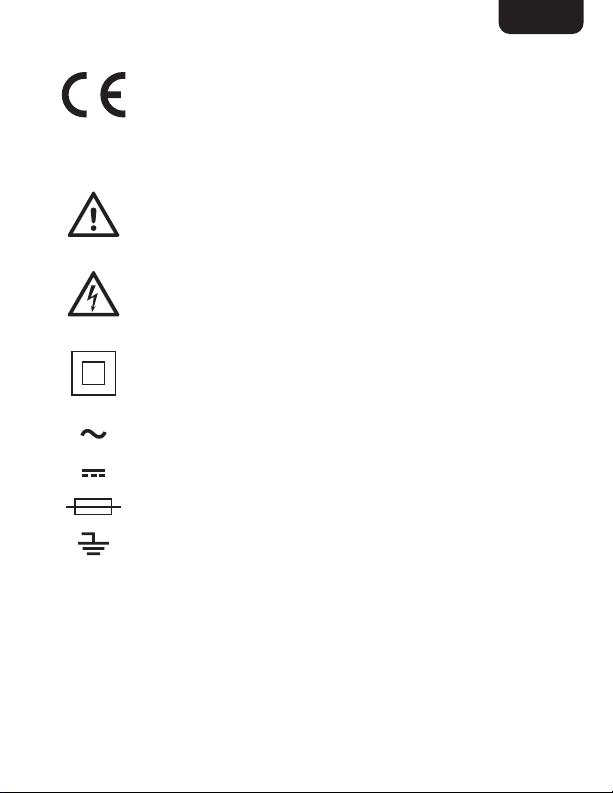
• This product is intended for measurements on electrical
installations and is protected by doubleinsulation as per
EN61010-1 to CATIII600 V; Pollution Degree 2.
• This product must be used by trained users only.
• Do not measure current on a CATIII circuitry whose voltage
exceeds 600V.
• When measuring volts, do not switch to current/resistance
modes.
• Set the function switch to the appropriate position before
measuring.
• Set the function switch to the OFF position when not in use.
• Inspect the condition of the connector leads and the product
for any damage before operation. Replace any damaged
accessory before use. Consult a professional repair centre
for any other repairs.

5
EN
• Do not exceed the maximum allowable input range of any
measurement mode.
Mode Maximum Input
A~, A 10 A, 600 V fast acting fuse (max.
30seconds every 15minutes)
mA~, mA 500 mA, 600 V fast acting fuse
V~, V 600 V ~RMS /
Frequency,
Resistance,
Capacitance, Diode
Test, Continuity,
Temperature
250 V ~RMS /
Surge Protection: 8 kV peak per EN61010
• When changing ranges always disconnect the connector
leads from the circuit under test.
• Always discharge capacitors and remove power from the
device under test before performing diode, resistance or
continuity tests.
• Voltage checks on electrical outlets can be difficult and
misleading because of the uncertainty of connection to the
recessed electrical contacts. Do not use this product for
checking socket outlets. Use special equipment for checking
socket outlets.
• Comply with all applicable safety codes. Use approved
personal protective equipment when working near live
circuits − especially with regard to the possibility of arc flash
hazards.
• Always remove the connector leads before replacing the
battery or fuses.

6
EN
Battery Warnings
• Always insert batteries correctly with regards to polarity
(+ and –) marked on the battery and the product.
• Exhausted batteries should be immediately removed from
product and properly disposed.
• Keep batteries out of the reach of children.
• Do not dispose of batteries in fire.
• Remove batteries from product if it is not to be used for an
extended period of time.
• If the battery leaks, avoid contact with skin and eyes. Rinse
affected areas immediately with plenty of clean water, then
consult a doctor.
Explanation of Symbols
WARNING The signal word that indicates a hazard with
a medium level of risk which, if not avoided,
could result in death or serious injury.
CAUTION
The signal word that indicates a hazard
that if not prevented could result in minor or
moderate injury.
NOTICE Indicates a practical tip, advice or practice
not related to personal injury.

7
EN
This symbol stands for “Conformité Européenne”,
which means “Conformity with EU-directives”. With
the CE marking the manufacturer confirms that this
product complies with applicable European directives
and regulations.
This symbol, adjacent to another symbol or terminal,
indicates the user must refer to the manual for
further information.
This symbol, adjacent to a terminal, indicates that,
under normal use, hazardous voltages may be
present.
Product is protected by double insulation or
reinforced insulation.
Alternating current (AC).
Direct current (DC).
Fuse
Earth (ground) terminal/potential.
CAT II
600V
Product is designed to protect the user during
measurements performed on circuits directly
connected to the low voltage installation.
CAT III
600V
Product is designed to protect the user during
measurements performed in the building installation
(up to 600 V).

8
EN
Intended Use
• This product is intended to perform electrical measurements
on CAT III locations (3-phase and single phase distribution).
• This product covers CAT II and CAT I locations.
• This product may be used only under the conditions and for
the purposes for which it was designed.
• No liability will be accepted for damages resulting from
improper use or non-compliance with these instructions.
Before First Use
• Check the product for transport damages.
• Remove all the packing materials.
DANGER Risk of suffocation! Keep any packaging
materials away from children – these materials are a potential
source of danger, e.g.suffocation.

9
EN
Product Description
10A
A
B
D
E
FH
I
CJ
G

10
EN
K
L
P
O
MQR
N
ANon-contact voltage
indicator JHOLD/ button
BDisplay KBattery compartment
CRANGE button L500 mA fuse
DMODE button M10 A fuse
EFunction switch NTilt stand
F10A input jack OTest probes with
connector leads
GCOM input jack PProbe tip shrouds
HV/Ω/Temp/Hz/%
/mA/μA input jack QTemperature probe
IREL Relative button R
Temperature probe
adapter with protection
cups

11
EN
1 2 3 4 5
7
8
10
11
12
13
6
9
1Auto Range indicator 8Units of measurement
2HOLD indicator 9Display reading
3REL Relative indicator 10 Low battery indicator
4Diode test 11 Minus sign
5Continuity 12 AC indicator
6Hz Frequency 13 DC indicator
7%Percent (dutycycle)

12
EN
Function switch
10A
Position Function / Measurement
Temperature
Frequency/ duty cycle
Resistance / diode test / continuity /capacitance
AC/DC voltage
OFF
AC/DC current up to 10 A
AC/DC current (mA)
AC/DC current (μA)

13
EN
Changing Batteries
WARNING Risk of electric shock! Disconnect the
product from any circuit, remove the connector leads (O) from
the input jacks (F)/(G)/(H) and switch off the product before
opening the battery compartment (K). Do not operate the
product with an open battery compartment.
NOTICE Replace the battery when the low battery
indicator (10) is shown on the display (B).
• Open the tilt stand (N).
• Loosen the screws of the battery compartment cover (K)
and remove it.
• Insert a 9 Vbattery and attach it to the snap connector.
• Place the battery in the battery compartment (K) and close it.
• Tighten the screws of the battery compartment (K).
Operation
NOTICE Keep the protection plugs of the connector leads
and reattach after use.
Switching the product on/off
• To switch the product on, set the function switch (E) to the
desired measurement mode.
• To switch the product off, set the function switch (E) to the
OFF position.

14
EN
Auto power off
• In order to conserve battery life, the product automatically
shuts off after it has been idle for approximately 30 minutes.
• Switch the product off and on again to light up the display
from standby mode.
Switching the display backlight on/off
• Press and hold the HOLD/button (J) to switch the display
backlight on/off.
Display hold
• To freeze the display reading, press the HOLD/button (J).
The HOLD indicator (2) lights up.
• Press the HOLD/button (J) again to return to normal
operation.
Changing the measurement range
By default, the measurement range is set automatically and
the Auto range indicator (1) lights up. It is possible to set the
measurement range manually.
• Press the RANGE button (C) to activate the manual mode
and to disable the automatic range setting. The Auto range
indicator (1) goes off.
• By every press on the RANGE button (C) the relevant
decimal place changes its position.
• If a reading is higher than the measurement range, OL lights
up on the display (B).

15
EN
• Press and hold the RANGE button (C) for more than
1second to exit manual mode and restore automatic range
setting. The Auto range indicator(1) lights up.
Relative measurement
The relative measurement feature allows you to make
measurements relative to a stored reference value.
• Initially, keep the test probes attached to the circuit or the
component to be measured.
• Press the REL button (I) to save this measurement as the
stored reference value and to zero the display. The REL
indicator (3) lights up.
• Press the REL button (I) again to return to normal operation
mode. The REL indicator (3) goes off.
NOTICE Relative measurement is not applicable for
functions:
Position Function / Measurement
Frequency/ duty cycle
Resistance / diode test / continuity /capacity
Temperature

16
EN
DC voltage measurement
NOTICE Doing voltage measurements while the (+) red
connector lead (O) is left on the ampere input jack (F) will blow
the product’s internal fuse if it draws a current greater than the
internal fuses current rating. Check that the (+) red connector
lead (O) is on the correct terminal.
NOTICE Risk of damage! Measure electric motors only in
steady and normal operation. At unstable operation, large
voltage surges or current inrush may occur that can damage the
product.
• Set the function switch (E) to the
position.
• Press the MODE button
(D) to select the DC voltage
measurement. The DC indicator
(13) lights up.
• Insert the black connector lead (O)
into the negative COM input jack
(G).
• Insert the red connector lead (O)
into the V/Ω/Temp/Hz/%/mA/μA input jack (H).
• Connect the test probes (O) in parallel to the circuit under
test.
• The stabilized value on the display (B) is read as the actual
reading.

17
EN
AC voltage measurement
WARNING Risk of electric shock! The contact plates of
powered AC outlets may be recessed too deep for the test
probes (O) to reach. This may give false measurements. Contact
point of measurement must be visible for a true reading.
NOTICE Risk of damage! Measure electric motors only in
steady and normal operation. At unstable operation, large
voltage surges or current inrush may occur that can damage the
product.
• Set the function switch (E) to the
position.
• Press the MODE button (D) to
select the AC voltage measurement.
The AC indicator (12) lights up.
• Insert the black connector lead (O)
into the negative COM input jack
(G).
• Insert the red connector lead (O)
into the V/Ω/Temp/Hz/%/mA/μA
input jack (H).
• Connect the test probes (O) in parallel to the circuit under
test.
• The stabilized value on the display (B) is read as the actual
reading.

18
EN
AC/DC current measurement
WARNING Risk of electric shock! To avoid electric
shock, do not measure AC current on any circuit which voltage
exceeds 250 V~.
NOTICE Do not make 10A current measurements for
longer than 30seconds. Exceeding 30seconds may cause
damage to the product and/or the connector leads (O).
• Insert the black connector lead (O) into the COM input jack
(G).
• For current measurements of up to 4000μA, set the
function switch (E) to the position and insert the red
connector lead (O) into the V/Ω/Temp/Hz/%/mA/μA input
jack (H).
• For current measurements of up to 400mA, set the function
switch (E) to the position and insert the red connector
lead (O) into the V/Ω/Temp/Hz/%/mA/μA input jack (H).
• For current measurements of up to 10A, set the function
switch (E) to the position and insert the red connector
lead (O) into the 10A input jack (F).
• Press the MODE button (D) to switch between AC and DC
mode. AC (12) or DC (13) lights up.
• Switch off the power to the circuit under test. Break the
connection line/track and separate securely the 2 points
where the flow of current must be measured.
• Connect in series by securely attaching each test probe (O)
at the 2 open points of the track/line.
• Apply power to the circuit.

19
EN
• The stabilized value on the display (B) is read as the actual
reading.
Frequency/duty cycle mode (AC)
WARNING Do not measure frequency/duty cycle on
circuits that exceed 250 V.
• Set the function switch (E) to the Hz% position.
• Insert the black connector lead (O) into the COM input jack
(G).
• Insert the red connector lead (O) into the V/Ω/Temp/Hz/%/
mA/uA input jack (G).
• Press the MODE button (D) to select frequency or duty
cycle. The Hz or %symbol will be shown on the display.
• Connect the test probes (O) in parallel to the circuit or
component being measured.
• The stabilized value on the display (B) is read as the actual
reading.
Resistance measurement
WARNING Risk of electric shock! To avoid electric
shock, disconnect power from the unit under test and discharge
all capacitors before taking any resistance measurements.
Remove the batteries and unplug the line cords.
NOTICE For best results, disconnect one side of the part
under test. So the rest of the circuit will not interfere with the
measurement.
• Set the function switch (E) to the position.

20
EN
• Press the MODE button (D) to switch to Ω resistance mode.
Ωresistance measure unit indicator (8) lights up.
• Insert the black connector lead (O) into the negative COM
input jack (G).
• Insert the red plug of connector lead into the V/Ω/Temp/
Hz/%/mA/μA input jack (H).
• Place the test probes (O) across the circuit or part under
test.
• The stabilized value on the display (B) is read as the actual
reading.
Diode test
• Set the function switch (E) to the position.
• Press the MODE button (D) to switch to diode test
mode. diode test indicator (4) lights up.
• Insert the black connector lead (O) into the negative COM
input jack (G).
• Insert the red connector lead (O) into the V/Ω/Temp/Hz/%/
mA/μA input jack (H).
• Place the test probes (O) across the diode being measured.
• If the diode was measured in reverse, the display(B) shows
OL. Reverse the probes (O) position to get the correct
polarity.
NOTICE Forward voltage typically indicates 0.4 to 0.7V. A
shorted diode indicates near 0V and an open diode indicates
OL in both polarities.
Table of contents
Languages:
Other Amazon Measuring Instrument manuals
Popular Measuring Instrument manuals by other brands

Topcon
Topcon CL-200 instruction manual

Hanna Instruments
Hanna Instruments HI 717 quick start guide

yellow jacket
yellow jacket 68940 Operation manual

Dynamica
Dynamica HALO DB-20 instruction manual

multicomp pro
multicomp pro MP780859 quick start guide

Hanna Instruments
Hanna Instruments HI88713-01 instruction manual