amber connect Amber Power C400 User manual

Quick Start Guide
APC400
Amber Power C400
LTE Vehicle Terminal
2
Download
Amber Connect
App
1
Install
Your device
3
Activate
the device

Product overview
Position tracking
•GPS & LBS positioning
•Real-time location query
Anti-theft
•Ignition detection
•Power/Fuel cut-off
•SOS emergency call
•Power supply disconnection alert Geo-fence alert
•Towing alert
•Vibration alert
Configurable peripherals
•Vehicle door status alert
•Turn light/buzzer triggering
•Fuel level monitoring
•Temperature monitoring
•Driver behavior monitoring
Specification
GSM Band
B5(850MHz)/B2(1900 MHz)
B8(900M Hz)/B3(1800M Hz)
LTE
B1/B2/B3/B4/B5/B12/B13/B28/B66 (APC400-LA)
B1/B3/B5/B8/B18/B19/B20/B26 (APC400-E)
GNSS Type
MTK all-In-one multi-GNSS SOC
Sensitivity
Cold start: <32s
Hot start: <1s
Position Accuracy (CEP50)
Autonomous: <1Om
Dimensions
106mm x 56.8mm x 22mm
Weight
104g
Backup Battery
Li-Polymer, 300 mAh

Operating Voltage
9V to 36V DC
Operating Temperature
-30°C to +85°C for storage
Transmit Protocol
TCP
Product setup
Insert SIM
Remove the soft plug on one side of the device and insert the SIM card into the card slot.
Power on & off
Toggle the power switch besides the SIM slot to power on or off the device.
LED indications
Power Status (Red}
Behaviour
Meaning
On for 0.1 s and off for 1 s 0%---20% remaining battery
On for 0.1 s and off for 4s 20%---100% remaining battery
Solid on Power supply connected
GNSS Status (Blue}
Behaviour
Meaning
On for 0.5s and off for 0.5s GNSS synchronizing
On for 2s and off for 4s Positioning
On for 0.1 s and off for 4s Positioned
Off GNSS module is in sleep mode or not working

Wireless Network & SIM Card Status (Green}
Behaviour
Meaning
On for 0.5s and off for 0.5s SIM card not recognized
On for 2s and off for 4s
Registered but no inbound
acknowledgement
On for 0.1 s and off for 4s Network connected
Off No signal received or no SIM card detected
Interfaces
PWR
Red
DC 9 to 36v input
Black
GND
Yellow
Relay control to cut vehicle fuel support
Orange
Vehicle ignite 12v/24v detection
TTL
Blue
TTL TX
Green
TTL RX
Red
DV 5v output max.500mah
Black
GND
EXT
Purple
Analog detect 0v to 30v
Orange
GND trigger digital input
Yellow
Extend relay control
SOS
Orange
DC 9 to 36v input
Black
GND

Wiring indication
Power connection
The standard power supply ranges from 9V to 36VDC.
During installation, negative side should connect to the ground. Do not connect with other ground
wires simultaneously.

Ignition wire
ACC line (orange) connects to vehicle's ACC, detecting ignition.
Be sure to check if it's a real ignition wire Le. power does not disappear after starting the engine.
Relay wiring
Relay's white line (85) connects to the positive side of battery (12V) while the yellow line (86)
connects to the device relay control (yellow line on the power cord).
Find the fuel pump in the vehicle and cut off its positive power line. The positive side of fuel pump
connects to the green line (87a) while the side closing to starter motor connects to green line (30)
, as the below chart. Switch of the two green lines have the same effect.
Configuration
If you need to change the setting of the device, you can either text the command to the device, or use
PC tool from supplier.
Note:
Texting command might be filtered by local carrier network deployment. In this case you can text
through web management center provided by the carrier.
Package & Standard accessories
•Standard package
•APC400 device
•Power cable
•1/0 cable
•Relay (12V/24V)
•SOS button cable

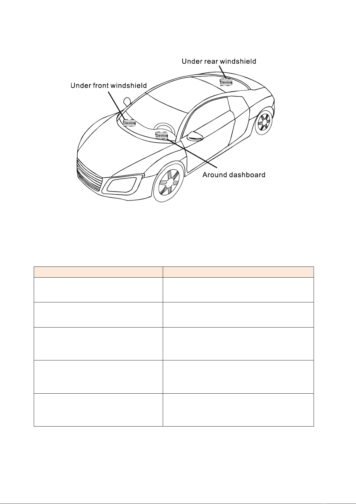
Installation recommendation
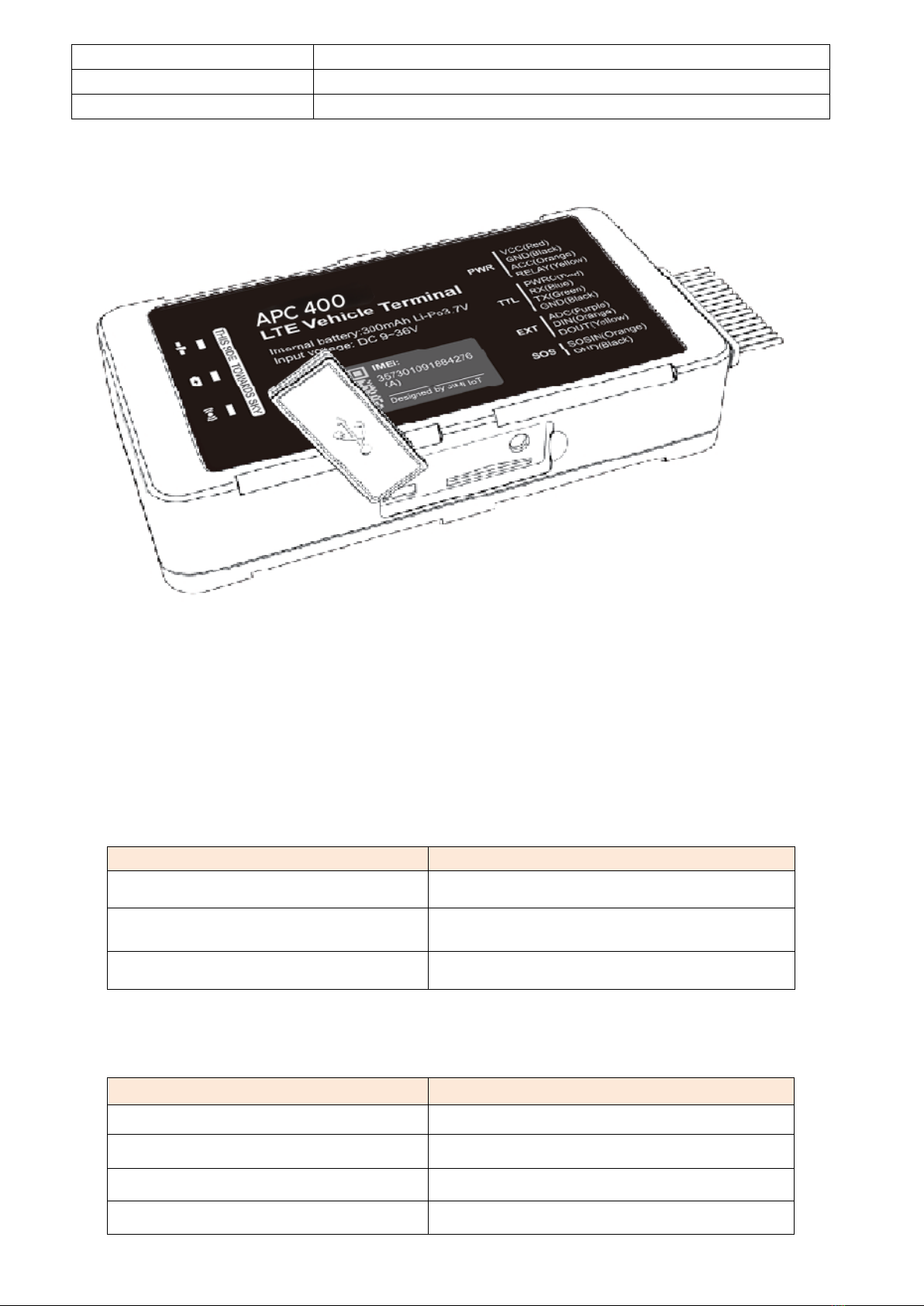
•The device should face up to the sky.
•Metal thermal barrier or heating layer of the windshield affects the signal.
Troubleshooting
Type
Use
Unable to connect to tracking platform
Check the APN and IP settings.
Check whether the data service of SIM card is
enabled. Check the balance of SIM card.
Tracker shows offline
Check whether external power is still connected.
Check if the vehicle entered network blind area.
Check the balance of SIM card.
Unable to locate
Make sure the top side facing upward without
metallic things shielded.
Make sure it's not in area with no satellite
coverage.
Location drift
In area with poor GNSS signal (tall building
around or basement), drifting may happen.
Check whether vibration happens around to
trigger the accelerator.
No command reply
Make sure command format is correct.
Vehicle may be in network blind area. Make sure
SIM card is well inserted and has SMS service.

Warranty instructions
1. The warranty is valid only when the warranty card is property completed, and upon presentation
of the proof of purchase consisting of original invoice indicating the date of purchase, model and
serial No. of the product. We reserve the right to refuse warranty if this information has been
removed or changed after the original purchase of the product from the dealer.
2. Our obligations are limited to repair of the defect or replacement the defective part or at its
discretion replacement of the product itself.
3. Warranty repairs must be carried out by our Authorized Service Centre. Warranty cover will be
void, even if a repair has been attempted by any unauthorized service centre.
4. Repair or replacement under the terms of this warranty does not provide right to extension or
renewal of the warranty period.
5. The warranty is not applicable to cases other than defects in material, design and workmanship
Table of contents