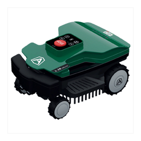
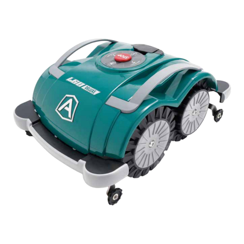
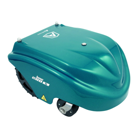
AMBROGIO BASIC User manual

Manuale d’uso
Rasaerba Robot
User's manual
Lawn Mower Robot
Manuel d’utilisation
Tondeuse à gazon Robot
Bedienungshandbuch
Rasenmähroboter
Manual de uso
Cortadora de césped Robot
Gebruiksaanwijzingen
Grasmaaimachine
I
GB
F
D
E
NL
Italiano
English
Français
Deutsch
Español
Nederlands
C141501700.fm
Congratulazioni per aver acquistato il rasaerba AMBROGIO. L'aver
scelto questo prodotto potrà soddisfare le vostre esigenze e
aspettative. Questo progetto nasce da ZUCCHETTI CENTRO
SISTEMI S.p.A. (Azienda certificata UNI EN ISO 9001) software
house che, dal 1982, ha consolidato la propria attività e la
propria presenza sul mercato internazionale. Le soluzioni
applicative del software abbinate al settore industriale di
automazione, fanno nascere prodotti nuovi che ottimizzano le
procedure di lavoro. È così che è nato, dai laboratori di ricerca,
AMBROGIO.
Congratulations for having purchased the AMBROGIO lawn
mower. This choice will surely meet your needs and
expectations. This product is the result of research at the
ZUCCHETTI CENTRO SISTEMI S.p.A. (certified UNI EN ISO
9001) software house that, since 1982, has been
consolidating its role on the international market. Innovative
software solutions applied to the industrial automation sector
introduce new products that optimise working procedures.
AMBROGIO was developed on the basis of this research.
Tous nos compliments pour avoir acheté la tondeuse à gazon
AMBROGIO. Vous avez choisi un produit qui répondra à vos
besoins et à vos attentes. Ce projet naît au ZUCCHETTI CENTRO
SISTEMI S.p.A. (Entreprise certifiée UNI EN ISO 9001) software
house qui, depuis 1982, a consolidé son activité et sa présence
sur le marché international. Les solutions d’application du
logiciel, jumelées au secteur industriel d’automation, ont permis
la naissance de nouveaux produits qui optimisent les
procédures de travail. C’est ainsi que, dans nos laboratoires de
recherche, est né AMBROGIO.
Wir gratulieren zum Kauf des Rasenmähers AMBROGIO. Ihre
Bedürfnisse und Erwartungen werden durch die Wahl dieses
Produkts mit Sicherheit erfüllt. Die Firma ZUCCHETTI CENTRO
SISTEMI S.p.A. (mit UNI EN ISO 9001 ausgezeichneter Betrieb)
Software House, die ihre Produktion seit 1982 festigt und
damit auf dem internationalen Markt vertreten ist, zeichnet für
dieses Produkt verantwortlich. Die angewandten
Softwarelösungen führen in Kombination mit der industriellen
Automatisierung zur Entstehung neuer Produkte für eine
Optimierung von Arbeitsprozessen. Auf diese Weise entstand
in den Forschungslabors AMBROGIO.
Felicidades por haber adquirido la cortadora de césped
AMBROGIO. Podrá satisfacer sus exigencias y expectativas al
haber elegido este producto. Este producto nace de
ZUCCHETTI CENTRO SISTEMI S.p.A. (Empresa certificada UNI
EN ISO 9001) software house que, desde 1982, ha
consolidado su propia actividad y su propia presencia en el
mercado internacional. Las soluciones de aplicación del
software combinadas con el sector industrial de
automatizando, hacen nacer nuevos productos que optimizan
los procedimientos de trabajo. Es así que ha nacido, en los
laboratorios de investigación, AMBROGIO.
Wij wensen u van harte geluk met de aanschaf van uw
AMBROGIO. Wij zijn er zeker van dat deze machine voldoet aan
al uw verwachtingen en vereisten. AMBROGIO is een project
van ZUCCHETTI (met UNI EN ISO 9001 certificaties), een
softwarebedrijf dat sinds 1982 met haar activiteiten een eigen
plaats verwierf op de internationale markt. De combinatie van
de oplossingen die worden geboden door
softwaretoepassingen en de industriële automatisering
resulteert in nieuwe producten om de bedrijfsprocessen te
optimaliseren. Zo ontstond in onze onderzoekscentra
AMBROGIO.

C141501700.fm
Dichiarazione di conformità (98/37 CE allegato II punto A)
ZUCCHETTI Centro Sistemi S.p.A. Via dell’Olmo 99 A/B
Terranuova B.ni (AR) ITALIA, dichiara che la macchina,
identificabile dai dati riportati in calce, da utilizzare per rasare
prati in ambienti domestici e non, è conforme alle direttive:
98/37 CE - 78/23 CEE - 89/336 CEE. Per queste ultime
sono compresi i successivi emendamenti.
Declaration of conformity (98/37 CE annex II paragraph A)
ZUCCHETTI Centro Sistemi S.p.A., Via dell’Olmo 99 A/B
Terranuova B.ni (AR) ITALY, declares that the machine,
identified by the data included hereafter, to be used for lawn
mowing in household and other environments, complies with
directives: 98/37 EC - 78/23 EEC - 89/336 EEC and
amendments thereto.
Déclaration de conformité (98/37 CE annexe II paragraphe A)
ZUCCHETTI Centro Sistemi S.p.A. Via dell’Olmo 99 A/B
Terranuova B.ni (AR) ITALIE, déclare que la machine,
identifiable par les données rapportées plus bas, servant à
tondre les pelouses en milieu domestique et non, est conforme
aux directives : 98/37 CE - 78/23 CEE - 89/336 CEE. Pour
ces dernières, sont inclus les amendements additionnels.
Konformitätsbestätigung (98/37 CE Beilage II Punkt A)
Die Firma ZUCCHETTI Centro Sistemi S.p.A., Via dell’Olmo 99
A/B Terranuova B.ni (AR) ITALIEN, erklärt, daß die mit den
unten angegebenen Daten gekennzeichnete Maschine, die
dazu bestimmt ist, zum Mähen von Rasenflächen in Wohn- und
anderer Umgebung eingesetzt zu werden, folgenden
Richtlinien entspricht: 98/37 CE - 78/23 CEE - 89/336 CEE.
Letztere schließen nachfolgende Abänderungen mit ein.
Declaración de conformidad (98/37 CE anexo II punto A)
ZUCCHETTI Centro Sistemi S.p.A. Via dell’Olmo 99 A/B
Terranuova B.ni (AR) ITALIA, declara que la máquina, que se
puede identificar por los datos al pie de la página, y que tiene
como uso cortar prados tanto en ambientes domésticos como
no domésticos, es conforme a las directivas: 98/37 CE - 78/
23 CEE - 89/336 CEE. Para estas últimas están incluidas las
enmiendas sucesivas.
Verklaring van overeenstemming (98/37 EG bijlage II punt A)
ZUCCHETTI Via dell'Olmo 99 A/B Terranuova B.ni (AR) ITALIA,
verklaart dat de machine waarvan de identificatiegegevens
hiernaast worden vermeld en die bedoeld is om gras te maaien
in huishoudelijke en andere omgevingen, voldoet aan de
richtlijnen: 98/37 EG - 78/23 EEG - 89/336 EEG. In de
laatste richtlijnen zijn ook de latere wijzigingen inbegrepen.
Modello/serie - Model/Series
Modèle/série - Modell/Serie
Modelo/serie - Model/serie
Bernini Fabrizio
(Amministratore delegato) - (Managing director)
(Administrateur délégué) - (Geschäftsführer)
(Administrador delegado) - (Afgevaardigd beheerder)
.............................................................................................................

- 3 -
C141501700.fm
User's manual
GB
GENERAL INFORMATION .............................. 4
TECHNICAL INFORMATION .......................... 5
SAFETY INFORMATION .................................. 9
INSTALLATION ................................................ 11
ADJUSTMENTS .............................................. 27
USE AND FUNCTIONING ............................ 29
ORDINARY MAINTENANCE ...................... 48
FAILURES, CAUSES AND SOLUTIONS .. 50
PARTS REPLACEMENTS ............................ 55
CONTENTS
A
Adjusting the cutting height, 28
Adjustment reminders, 27
Automatic cycle start, 38
B
Batteries replacement, 56
Battery installation and connection, 23
Blade installation, 23
D
Display visualisation in work phase, 42
E
Enter password, 42
Equipment general description, 5
Equipment installation planning, 12
I
Identification of manufacturer and appliance, 4
Installation of recharging station and
transmitter-power supplier group, 20
M
Maintenance reminders, 48
Manual startup and stop of robot (in closed areas), 40
O
Operating reminders, 48
P
Packaging and unpacking, 11
Parts replacement reminders, 55
Perimeter wire installation, 17
Preparation and delimitation of work
areas (main and secondary), 14
Programmed maintenance intervals chart, 48
Programming mode, 31
Prolonged inactivity and service restart, 42
Purpose of this manual, 4
R
Rain sensor adjustment, 29
Recharge batteries for extended inactivity, 44
Recharge batteries on first use, 27
Recommendations for use, 29
Remote control description, 31
Replace the blade, 61
Requesting technical assistance, 5
Robot automatic stop, 39
Robot cleaning, 49
Robot controls description, 30
Robot disposal, 62
Robot safety stop, 39
Robot start without perimeter wire, 41
S
Safety for man and the environment
during disposal, 10
Safety rules, 9
Safety signals, 11
Setting for rapid robot re-entry into the
recharging station, 19
Specifications, 7
T
Telecommand batteries replacement, 62
Troubleshooting, 50
ANALYTICAL CONTENTS
Reproduction, even partial, of thisdocument without written permission bythe manufacturer is forbidden. The manufacturer assumes a policy of continual improvement and reserves the right to modify this do-
cumentwithout priornoticeon conditionthat modificationsdo notconstitute safetyrisks.
©2002 -Text,illustrationsandpage settingby: IDMexpertsintechnicalcommunications -Forlì -Texts maybe partiallyor totallyreproduced iftheauthor iscited.

- 4 -
C141501700.fm
User's manual
GB
The constructor has produced this man-
ual, which forms an integral part of the
appliance, to provide the necessary infor-
mation for those authorised to interact
with it during its working life.
Personnel working with the machine must
adopt correct working practices and must
also carefully read and strictly follow all the
instructions given in this manual.
This manual is written by the manufac-
turer in the original language (Italian). It
may be translated into other languages
to satisfy commercial and/or legal re-
quirements.
Study this manual carefully. It will help
you avoid unnecessary risks to personal
health and safety and risks of damage to
equipment.
The constructor reserves the right to
make changes without any obligation to
provide any prior notice.
Some information and illustrations set
out in the present manual may not per-
fectly correspond with the one in your
possession, but that does not compro-
mise its validity.
The manufacturer reserves the right to
make all necessary changes without pri-
or notice of any kind.
The following symbols are used through-
out this manual to identify particularly im-
portant sections of text or data.
Danger - Attention
This symbol identifies situations of im-
minent danger which, if ignored, lead to
serious risks to personal health and
safety.
Warning - Caution
This symbol identifies situations in
which it is essential to behave in a cer-
tain way to avoid risks to personal
health and safety and risks of damage
to equipment.
Important
This symbol identifies specially impor-
tant technical information that must
not be ignored.
The dataplate shown here is fit-
ted directly to the appliance. It
features references and all es-
sential information for operating
safety.
A) Name of manufacturer
B) CE conformity label.
C) Serial model/number year of
construction.
D) Technical specifications
GENERAL INFORMATION
PURPOSE OF THIS MANUAL
IDENTIFICATION OF MANUFACTURER AND APPLIANCE
IDM - 41501700100.tif
manufacturer identification (A)
CE conformity marking (B)
model (C)
technical specifications
(D)
serial number (C)
manufacturing year (C)

- 5 -
C141501700.fm
User's manual
GB
For every technical service request re-
garding the machine, please indicate the
data found on the identification plate, the
approximate hours of use and the type of
fault detected.
The appliance Ambrogio Line
200 is a robot designed and built
to automatically trim grass in gar-
dens and house lawns in any time
of the day. It is small, compact, si-
lent, waterproof and easy to
transport.
Relative to the various specifica-
tions of the sufrace to be mown,
the robot can be programmed to
machine a number of areas: a
main one and, in addition, two or
three secondary areas.
During its functioning the robot
trims the area marked off by the
perimeter wire and/or by barri-
ers (fences, walls, etc.)
When the robot detects the per-
imter wire or meets an obstacle it
changes trajectory in a random
manner and starts again in a new
direction.
According to its functioning prin-
ciple ("random"), the robot car-
ries out an automatic and
complete trimming of the
marked off lawn (see figure).
The lawn surface that the robot
is able to trim depends on a series of fac-
tors.
– robot model and type of batteries in-
stalled
– area features (irregular perimeters,
uneven surface, divided area, etc.)
– lawn features (type and height of
grass, moisture, etc.)
– blade conditions (with efficient sharp-
ening, without residues and deposits,
etc)
REQUESTING TECHNICAL ASSISTANCE
TECHNICAL INFORMATION
EQUIPMENT GENERAL DESCRIPTION
IDM - 41501700200.tif
robot
robot

- 6 -
C141501700.fm
User's manual
GB
The robot Ambrogio Line 200 is pro-
duced in the BASIC, DELUXE and EVOLU-
TION versions.
BASIC version: basic model which can
mow surfaces up to 1500 m2. On re-
quest, it can be equipped with two lead
batteries or a lithium battery.
DELUXE version: model able to mow
surfaces up to 2600 m2. On request, it
can be equipped with two lithium batter-
ies, which make it possible to mow sur-
faces up to 3000 m2.
EVOLUTION version: model able to mow
surfaces up to 3000 m2. It is equipped
with two lithium batteries, telecommand
and sensor to detect the "mown lawn".
All models are equipped with a sensor
which, when it rains, stops the blade and
makes the robot return to its recharging
station.
On request, models can be equipped
with an amplified transmitter, electro-
magnetic interferences filter, electronic
alarm and power supply protection box.
For more details, consult the table show-
ing technical data
Each robot is provided with a recognition
password in order to impede its use
should it be stolen.
When the purchased, the password in-
serted by the manufacturer comprises
four numbers (0000).
To customise the password see "Pro-
gramming mode" (§ "Enter password").
Main parts
–Accumulator batteries (A): they en-
ergize the motors of the blade and of
the wheel control system.
The robot is supplied with lead batter-
ies or with one or two lithium batter-
ies, which assure a longer working
session.
–Recharging station (B): used to
charge or keep the batteries charged
(A).
–Electronic card (C): it checks the au-
tomatic functions of the robot.
–Control keyboard (D): it is used to set
and visualise the functioning modes of
the robot.
–Cutting blade (E): it trims the lawn.
–Electric motor (F): it starts the cut-
ting blade (E).
–Electric motor (G): one actions the
right wheel transmission group while
the other actions the left wheel.
–Transmitter (H): it transmits the sig-
nal to the perimeter wire.
–Power supply unit (L): it energizes, at
low tension, the battery power.
Important
The power supply unit (L) varies ac-
cording to the type of batteries in-
stalled (lead or lithium batteries).
–Impacts sensor (M): detects robot
impact against an obstacle and ena-
bles a change of trajectory in a ran-
dom manner.
–Remote control (N): it is used to
check the robot functions in a remote
position.
–Rain sensor (P): detects rain and en-
ables the return of the robot to its
charging station (P).
–Sensor (Q): detects the perimeter
wire and enables a change of robot
trajectory in a random manner.

- 7 -
C141501700.fm
User's manual
GB
SPECIFICATIONS
Description Model
BASIC DELUXE EVOLUTION
Cutting blade 4 (mm) 220 290 290
Cutting speed (m/min) 25 25 25
Cutting height (mm) 20-60 20-60 20-60
Maximum gradient of the surface
to trim 27°
Electric motors (V) cc (24V) cc (24V) cc (24V)
Size (basexheightxdepth) (mm) 610x410x265 610x410x265 610x410x265
Robot weight (without batteries) (kg) 9,2 9,2 9,2
Ambient functioning temperature Max 40° 40° 40°
signal transmitter (H)
Reload station (B)
control keyboard (D)
electric motor (F)
cutting blade (E)
accumulator
batteries (A)
shock sensor
(M)
remote control (N)
power supply unit (L)
electronic card (C)
IDM - 41501700300.tif
Rain sensor (P)
electric motor (G)
Perimeter wire
sensor (Q)

- 8 -
C141501700.fm
User's manual
GB
Battery accumulator recharge type
battery accumulators (lead) (V/A) 27,6V - 4A -
battery accumulators (lithium) (V/A) 29,3V - 4A 29,3V - 4A 29,3V - 4A
Maximum surface that can be trimmed
Robot with two lead batteries
(12V-12A) m21500 - -
Robot with one lithium battery
(25.2V-6A) m21500 2600 -
Robot with two lithium batteries
(25.2V-6A) m2-3000 3000
Electric specifications
Power supply unit (for lead
battery)
Class 1 (Vin 115-230 Vac 50Hz) Fuse 5x20 4A
F (inside) 27,6 Vac Fuse 5x20 10A F
(replaceable) Selector 115-230 Vac
Power supply unit (for lithium
battery)
Class 1 (Vin 115-230 Vac 50Hz) Fuse 5x20 4A
F (inside) 29,3 Vac Fuse 5x20 10A F
(replaceable) Selector 115-230 Vac
Section perimeter wire (to lay
underground) (mm) ø1,5 ø1,5 ø1,5
Perimeter wire maximum length
(approximate, calculated
according to a regular perimeter)
(m) 600 600 600
Fittings
Sinusoidal perimeter signal
(patented) standard standard standard
Rain sensor standard standard standard
Intelligent spiral not available standard standard
Blade modulation not available standard standard
Trimmed lawn sensor -
Auto-programming (patented) not available not available standard
Remote control on request on request standard
Alarm on request on request standard
Kit for working with gradients
higher than 27° (1) on request on request standard
Perimeter wire (m) 100 150 150
Fixing nails (n°) 100 200 200
Upgraded transmitter on request on request on request
Electromagnetic interference
filter on request on request on request
Power supply safety box on request on request on request
Description Model
BASIC DELUXE EVOLUTION

- 9 -
C141501700.fm
User's manual
GB
– During design and construction, the
manufacturer has carefully consid-
ered the possible hazards and per-
sonal risks that may result from
interaction with the machine. In addi-
tion to observing the specific laws in
force, the manufacturer has adopted
all "exemplary construction technique
principles". The purpose of this infor-
mation is to advise the users to use
extreme caution to avoid risks. How-
ever, discretion is invaluable. Safety is
also in the hands of all the operators
who interact with the machine.
– When using the robot for the first
time, it is recommended to carefully
read the whole manual and to be
sure to have it completely under-
stood, in particular all the informa-
tion relating to safety.
– Carefully read all instructions in this
manual and those applied directly to
the machine, taking particular care to
read and follow safety precautions.
Time dedicated to reading these pre-
cautions can prevent regrettable ac-
cidents. It is always too late to
remember what you should have
done after an accident has happened.
– Perform lifting and handling observing
the information found directly on the
packaging, on the machine and in the
instructions furnished by the manu-
facturer.
– Pay attention to the symbols that ap-
pear on all the safety labels. They are
coded by colour and shape to en-
hance safety. Keep all safety labels
legible and always respect the instruc-
tions they give.
– The lawn mower may be used only by
those who know how to operate it af-
ter reading and understanding the in-
structions in this manual.
– Only use the machine for the purpos-
es specified by the manufacturer. Use
of the machine for other purposes
may be hazardous to personal safety
and health and provoke economic
loss.
– Before using the lawn mower make
sure that no objects are on the lawn
(toys, tree branches, items of cloth-
ing, etc.).
– When using the machine, make sure
there are no risks especially for chil-
dren, pets and things.
– Do not place hands or feet under the
machine when running especially in
the wheel area.
Battey charger kit (winter period
or extended inactivity) on request on request on request
Wheels with "nailed" tread on request on request on request
Wheels with "claws" profile tread on request on request on request
(1) If the ground conditions are suitable (solid, without excessive folds, etc.), the kit allows the robot to work (within
certain limits) beyond the maximum admissible gradients.
SAFETY INFORMATION
SAFETY RULES
Description Model
BASIC DELUXE EVOLUTION

- 10 -
C141501700.fm
User's manual
GB
– Never tamper with, avoid, remove or
bypass installed safety devices. Such
actions could lead to serious risk to
personal health and safety.
– Keep the lawn mower in perfect oper-
ating conditions by performing the
maintenance procedures outlined by
the manufacturer. Good maintenance
guarantees better performance and
longer service life.
– Before maintenance and setting pro-
cedures are performed – also by the
user, if possessing the necessary
technical skills – disconnect the pow-
er supply. The user must in any case
operate in full safety conditions, espe-
cially when working on the lower part
of the lawn mower, following the pro-
cedures as illustrated by the manu-
facturer.
– Use personal protections as recom-
mended by the manufacturer, espe-
cially the protective gloves when
handling blades and cutting discs.
– Always remove the blade before re-
placing the batteries.
– In order not to irreversibly damage
electric and electronic parts, do not
wash the robot with water jets at a
high pressure and do not plunge it
partially or thoroughly in water, as it
is not watertight.
– The operators performing repair in-
terventions during the working life of
the robot must have technical exper-
tise, special abilities and experience,
acquired and acknowledged in this
specific sector. The lack of these re-
quirements may cause damage to the
safety and health of people.
– All operations, which must be carried
out in the recharge base (optional),
must be performed with the power
supply plug disconnected.
– Replace deteriorated parts with origi-
nals to ensure functionality and the
foreseen safety level.
Do not dispose of pollutant materials in
the environment. Dispose of all such
materials in compliance with applica-
ble legislation.
With reference to the WEEE directive
(Waste of Electrical and Electronic
Equipment), during dismantling, the user
must separate the electrical and the
electronic components and dispose
them in the appropriate authorized col-
lection centres or give them back as they
are to the seller, when a new purchase is
made.
All the components, which must be sep-
arated and disposed of in a specific man-
ner, are marked with a special mark.
The unauthorized disposal of Waste of
Electrical and Electronic Equipment
(WEEE) is subject to fine according to
sanctions regulated by the laws in force
in the territory where the infraction has
been verified.
As implementation of the European di-
rectives (2002/95/CE, 2002/96/CE,
2003/108/CE) in the Italian territory,
for example, a law decree (n. 151 dated
July 25 2005) has been enacted, thus
providing for an administrative fine of
€2000÷5000.
Danger - Attention
The Waste of Electrical and Electronic
Equipment may contain dangerous
substances with potentially harmful ef-
fects on the environment and on peo-
ple. It is recommended to correctly
dispose them.
SAFETY FOR MAN AND THE ENVIRONMENT DURING DISPOSAL

- 11 -
C141501700.fm
User's manual
GB
Danger signal: indicates
that the user should not ap-
proach to the blades while
the lawn mower is operat-
ing.
Safety signal: indicates
that the user should care-
fully read the manual be-
fore operating the lawn
mower.
The machine is delivered suitably pack-
aged. When unpacking, remove carefully
and check component integrity.
All the necessary information for han-
dling is found on the packaging.
Packaging content
–Robot(A);
– Power supply unit (B)
– Power supply cable (C)
– Reload station (D)
–Transmitter(E)
– Perimeter wire hank (F)
–Nails(G) for wire fixing
– User manual (H)
– Lithium or lead accumulator batteries
(L): the quantity of batteries can vary
relative to the purchase order.
–Blade(M)
– Telecommand (N) (only for some ver-
sions, see "Specifications").
Important
The list includes only the components
supplied with the equipment. Check the
quantity and the integrity of any option-
al parts requested.
Keep packaging material for subse-
quent use.
SAFETY SIGNALS
INSTALLATION
PACKAGING AND UNPACKING
IDM - 41501700400.tif
user manual (H)
robot (A)
wire fixing nails (G)
perimeter wire (F)
remote control (N)
cutting blade
(M) power supply
unit (B)
Reload station (D)
transmitter (E)
accumulator batteries
(L)
power cable (C)

- 12 -
C141501700.fm
User's manual
GB
Robot installation does not involve inter-
ventions that are difficult to carry out,
but requires a minimum of preliminary
planning to define the best area to install
the charging station, power supply-trans-
mitter group and to lay out the perime-
ter wire.
Power supplier-transmitter
group and recharging station in-
stallation area
– Power supplier-transmitter
group and recharging station
must be installed inside the
main work area and near to
each other.
– The recharging station must be
positioned on a flat and stable
surface and able to guarantee
good drainage to avoid flooding.
– The section of input wire must
be rectilinear and aligned per-
pendicularly to the recharging
station for at least 2 m and the
output section must be located
at least 30 cm from the re-
charging station; this makes it
possible for the robot to enter
correctly.
EQUIPMENT INSTALLATION PLANNING
IDM - 41501700500.tif
power supply-transmitter unit
perimeter wire
wire laying direction
IDM - 41501700500.tif
Reload station perimeter
wire
power supply-
transmitter unit
power supply-transmitter unit
IDM - 41501700600.tif
power supply-transmitter unit
IDM - 41500902400.tif

- 13 -
C141501700.fm
User's manual
GB
Important
To permit the robot to re-enter the re-
charging station, it is necessary to in-
stall the same within the work area
having larger dimensions, hereafter re-
ferred to as the "Main Area".
– Make sure that any irrigators ,
present in the installation area do not
direct a jet of water into the recharg-
ing station.
– The transmitter - power supplier
group must be in a ventilated position,
protected from the atmospheric
agents and from direct sunlight.
– The transmitter - power supplier
group must not be in direct contact
with the ground and damp environ-
ments.
Warning - Caution
To carry out electric connection, it is
necessary to arrange a power supply
socket near the installation area. Make
sure that the connection to the power
supply complies to the laws in force on
the subject.
Important
Is it advisable to install the unit in a
closet for electric components (for out-
doors or indoors), well ventilated to
keep a correct air recirculation and
provided with a key closure.
Warning - Caution
Assure that the access to the power
supply-transmitter unit is allowed only
to authorized people.
Perimeter wire path definition
– Check the whole surface of the
lawn and assess whether it is
necessary to divide it in more
separated working areas.
– When positioning the perimter
wire, respect the rotation direc-
tion around the bays (anticlock-
wise).
– Define the perimeter of the
main area, any secondary are-
as, and carry out the opera-
tions in the sequence indicated.
1-Preparation and delimitation
of work areas (main and sec-
ondary) (see page 14)
2-Perimeter wire installation
(see page 17)
3-Installation of recharging sta-
tion and transmitter-power
supplier group (see page 20)
IDM - 41500902500.tif
track for perimeter wire
laying

- 14 -
C141501700.fm
User's manual
GB
Arrangement of lawn to trim
1-Check that the lawn to trim is
even, and without pits, stones
or other obstacles. If so, per-
form the necessary clearance
operations.
If some obstacles cannot be
removed, it is necessary to
properly mark the areas in-
volved.
2-Check that all the areas of the
lawn do not exceed the admis-
sible gradients (see "Specifica-
tions"). During the work phase
on slopes, when the robot de-
tects the wire the wheels may
slide and make it exit from the
perimeter area. To avoid this
problem, it is possible to install the
"Slopes kit" and the "Clawed" wheels.
Important
The areas, showing higher gradients
than those admitted cannot be
trimmed with the robot.
If the proper kit is installed and the condi-
tions of the ground are suitable (solid,
without excessive folds, etc.), the robot
can work (within certain limits) beyond
the maximum admissible gradients.
see figure
PREPARATION AND DELIMITATION OF WORK AREAS
(MAIN AND SECONDARY)
Marking of working area
3-Check the whole surface of the
lawn and assess whether it is
necessary to divide it in more
separated working areas.
Before starting installation op-
erations of the perimeter wire,
to make them easy to perform,
it is recommended to properly
signal the whole path evenly
with straight lines and to trace
any curved line.
The figure represents an ex-
ample of lawn with the trace
for the underground laying of
the perimeter wire.
IDM - 41501700800.tif
track for perimeter wire
laying
IDM - 41501600700.tif

- 15 -
C141501700.fm
User's manual
GB
Important
To ensure the robot can operate,
it is necessary for the distance
separating the delimitation of
two elements to be greater than
70 cm. This distance is required
to permit robot passage.
When the connection between
one surface and another of the
lawn is represented by a pas-
sage (corridor) with a width of
less than 70 cm and not greater
than 2 m, it is necessary to de-
limit the same with the perime-
ter wire in a number of work
areas that are connected to
each other.
IDM - 41501700900.tif
house
passage aisle
house
passage aisle (<
70cm)
MAIN AREA SECONDARY
AREA
MAIN AREA
Closed area

- 16 -
C141501700.fm
User's manual
GB
4-Mark and trace the perime-
ters of the inside and marginal
elements of the working area
that obstruct the correct func-
tioning of the robot.
Important
The figure represents an exam-
ple of inside an marginal ele-
ments of the working area and
the distances that must be re-
spected for the tracing of the un-
derground laying of the
perimeter wire.
Mark and trace the perimeters
of all the elements in iron or in
other metals (manholes, electric
connections, etc.) to avoid inter-
ferences to the signal of the pe-
rimeter wire.
Do not mark those obstacles
(trees, poles, etc.) that do not
hamper the normal functioning
of the robot.
IDM - 41501601100.tifIDM - 41501711400.tif
bed
manhole
hedge
protruding roots
wall
pool
shower dish
IDM - 41501701000.tif
tree pole

- 17 -
C141501700.fm
User's manual
GB
5-Mark the areas, located in a
lower position compared to
the lawn surface (pools, areas
with significant drops, stairs,
etc.) (see example in figure).
Important
Strictly respect the distances to
avoid that the robot falls with the
risk of breaking and/or seriously
getting damaged.
6-Mark and trace the perime-
ters as shown in the figure.
– With small paths at the same
height as the lawn: 5 cm
– With small paths higher than
the lawn: 35 cm
– In presence of a fencing wall:
35 cm
Important
The passage paths (at the same
level of the lawn), necessary for
the robot to pass from one area
to the other, must not be
marked.
The perimeter wire may be laid un-
derground or on the ground.
Important
Start laying the perimeter wire
from the installation area of the
recharging station , leave two
metres in excess and then cut it
as appropriate in the group con-
nections phase.
PERIMETER WIRE INSTALLATION
pool
IDM - 41501701100.tif
elevated area
perimeter wire
pedestrian crossing
wall
pedestrian crossing
IDM - 41501701200.tif
perimeter wire
perimeter wire
perimeter wire
IDM - 41501601600.tif

- 18 -
C141501700.fm
User's manual
GB
Wire laid on the ground
1-Place the wire clockwise along
the whole path and fix it with
the appropriate nails supplied
(distance between the nails
1÷2 m).
– When positioning the perimter
wire, respect the rotation di-
rection around the bays (anti-
clockwise).
– In the straight stretches, fix the
wire so that it is not excessively
tight, wavy and/or twisted.
– In the not straight stretches, fix
the wire so that it does not
twist, but so that it takes on a
regular bending.
Underground laid wire
1-Dig up the ground evenly and sym-
metrically compared to the traced
line highlighted on the ground.
2-Place the wire clockwise along the
whole path at the depth of some cen-
timetres (about 2÷3 cm) so not to
reduce the quality and the intensity of
the signal captured by the robot.
3-When laying the wire, if necessary,
block it in some points with the appro-
priate nails to keep it in position dur-
ing the ground covering stage.
4-Cover up the whole wire with the soil
and make sure that it does not twist,
but that it remains straight and that,
in the curving stretches, it takes on
an even bending.
Important
In the path stretches, where it is
necessary to pass two parallel
wires (for example: connection
between the outside perimeter
and the inside marked areas),
they must be at a distance,
which must not exceed 1 cm.
IDM - 41501600900.tif
wire fixing nails
wire fixing nails
perimeter wire
perimeter wire
IDM - 41501701300.tif
passage aisle (<
70cm)
MAIN AREA
Closed
area

- 19 -
C141501700.fm
User's manual
GB
Perimeter wire joint
Important
In the case of underground wire
as well as of ground laid wire, if
necessary, properly join it with
some other wire, having the
same features (see figure).
During the joint stage, it is rec-
ommended to use self-amalga-
mating tape (for example: 3M
Scotch 23). Do not use isolating
tape or other types of joints (ter-
minals, clamps, etc.).
To reduce the times for robot re-
entry into the recharging station,
carry out settings along the perim-
eter wire to permit a change of ro-
bot direction. In this way, it is
possible to reduce the robot re-en-
try route.
To carry out the re-entry setting,
position the perimeter wire along
the route< so as to form an equi-
lateral triangle of 40 cm per side.
Carry out the rapid re-entry set-
ting at a point that is preceded by
at least 2 m of rectilinear wire and
is followed by at least 1.5 m of rec-
tilinear wire.
The setting must not be carried
out along the rectilinear section
that immediately precedes the recharg-
ing station or near to obstacles. Make
sure that along the rapid re-entry trajec-
tory, there are no obstacles that can im-
pede rapid re-entry.
Important
The rapid re-entry setting at an incor-
rect point may prevent the robot from
rapidly re-entering the recharging sta-
tion.
When the robot moves along the pe-
rimeter to reach a secondary area it
does not detect the rapid re-entry set-
ting.
The illustration provides some useful in-
dications for correctly installing the rapid
re-entry setting.
SETTING FOR RAPID ROBOT RE-ENTRY INTO THE
RECHARGING STATION
IDM - 41501701400.tif
IDM - 41501602000.tif

- 20 -
C141501700.fm
User's manual
GB
1-Identify the recharging station
installation area and the trans-
mitter-power supply group.
Warning - Caution
Before carrying out any interven-
tion deactivate the general elec-
tricity power supply.
2-Installation of the power sup-
ply-transmitter unit (A-B).
3-Remove the shield (L).
INSTALLATION OF RECHARGING STATION AND
TRANSMITTER-POWER SUPPLIER GROUP
IDM - 41501701700.tif
power supply unit (A)
transmitter (B)
IDM - 41501701500.tif
guard (L)
Other manuals for BASIC
2
This manual suits for next models
4
Table of contents
Other AMBROGIO Lawn Mower manuals

AMBROGIO
AMBROGIO BASIC User manual

AMBROGIO
AMBROGIO L400i Basic User manual

AMBROGIO
AMBROGIO L15 Deluxe User manual

AMBROGIO
AMBROGIO L60 User manual

AMBROGIO
AMBROGIO LINE 250 User manual

AMBROGIO
AMBROGIO L250 Deluxe User manual

AMBROGIO
AMBROGIO 6060BA0 User manual

AMBROGIO
AMBROGIO BASIC User manual

AMBROGIO
AMBROGIO L15 Deluxe User manual
Popular Lawn Mower manuals by other brands

Murray
Murray 40601A-DECK Illustrated parts list

Husqvarna
Husqvarna R112C5 Operator's manual

Scheppach
Scheppach MS161-46 Translation from the original instruction manual

Toro
Toro Z Master Professional 5000 Series Operator's manual

Craftsman
Craftsman 917.377425 owner's manual

DO IT+GARDEN
DO IT+GARDEN BM 46 manual