AMEC CAMINO-108S User manual

CAMINO-108S
AIS Class B with
Integrated Splitter
USER MANUAL


3
COPYRIGHT
The entire contents of this instruction manual, including any future updates, revisions,
and modifications, shall remain the property of AMEC at all times. Unauthorized copies
or reproduction of this manual, either in part or whole, in any form of print and
electronic media, is prohibited. The contents herein can only be used for the intended
purpose of this manual.
DISCLAIMER
AMEC is devoted to publish and maintain this product manual. As we continue to
improve our AIS products to satisfy all customers’ needs, information in this document
is subject to change without notice. AMEC does not make any representations or
warranties (implied or otherwise) regarding the accuracy and completeness of this
document and shall in no event be liable for any loss of profit or any commercial
damage, including but not limited to special, incidental, consequential, or other
damage.
Manual Revision: Version 1.2
User’s Manual

4
WARNING!
WARNING: The transponder must be installed and configured in conformity with
the provided instructions in the manual by qualified installer in order to ensure
the device performance.
WARNING: It is the responsibility of the operator to handle the AIS device with
care. The device cannot replace human vigilance. Therefore it is important to
keep a diligent outlook at all times.
WARNING: Please bear in mind that not all vessels are equipped with AIS
transponders and therefore may not be visible to this transponder. Likewise,
certain conditions, such as device malfunction, the environment, improper use,
and overcrowded port traffic, may exist whereby the vessel equipped with this
AIS transponder is not visible to other AIS transponders.
WARNING: DO NOT DISASSEMBLE OR MODIFY THE EQUIPMENT. Improper
disassembly or modification could impair its performance and will invalidate the
guarantee.
FOR USERS IN THE UNITED STATES OF AMERICA ONLY
WARNING: It is a violation of the rules of the Federal Communications
Commission to input an MMSI that has not been properly assigned to the
end user, or to otherwise input any inaccurate data in this device.
★ The entry of static data into this device shall be performed by the vendor of
the device or by an appropriately qualified person in the business of installing
marine communications equipment on board vessels.
★ Instructions on how to accurately enter and confirm static data in the device
can be found in this user manual.
FOREWORD
We thank you for the purchase of your new CAMINO-108S AIS class B transponder with
built-in splitter. Wherever you sail now, you can have a better overview of your
surroundings at sea and voyage with more safety.
CAMINO-108S is strictly tested to meet the rigorous demands of the marine
environment. With proper installation and use, the equipment will serve loyally and
reliably at its optimum.
For sales, services, and technical supports, please contact your local AMEC
representatives or Alltek Marine Electronics Corp at sales@alltekmarine.com or
service@alltekmarine.com. You are always welcome to visit our website at
www.alltekmarine.com for new product status and company update.
Thank you again. Be safe.

5
TABLE OF CONTENT
1SYSTEM OVERVIEW ........................................................................................................................... 6
1.1 PRODUCT DESCRIPTION..........................................................................................................6
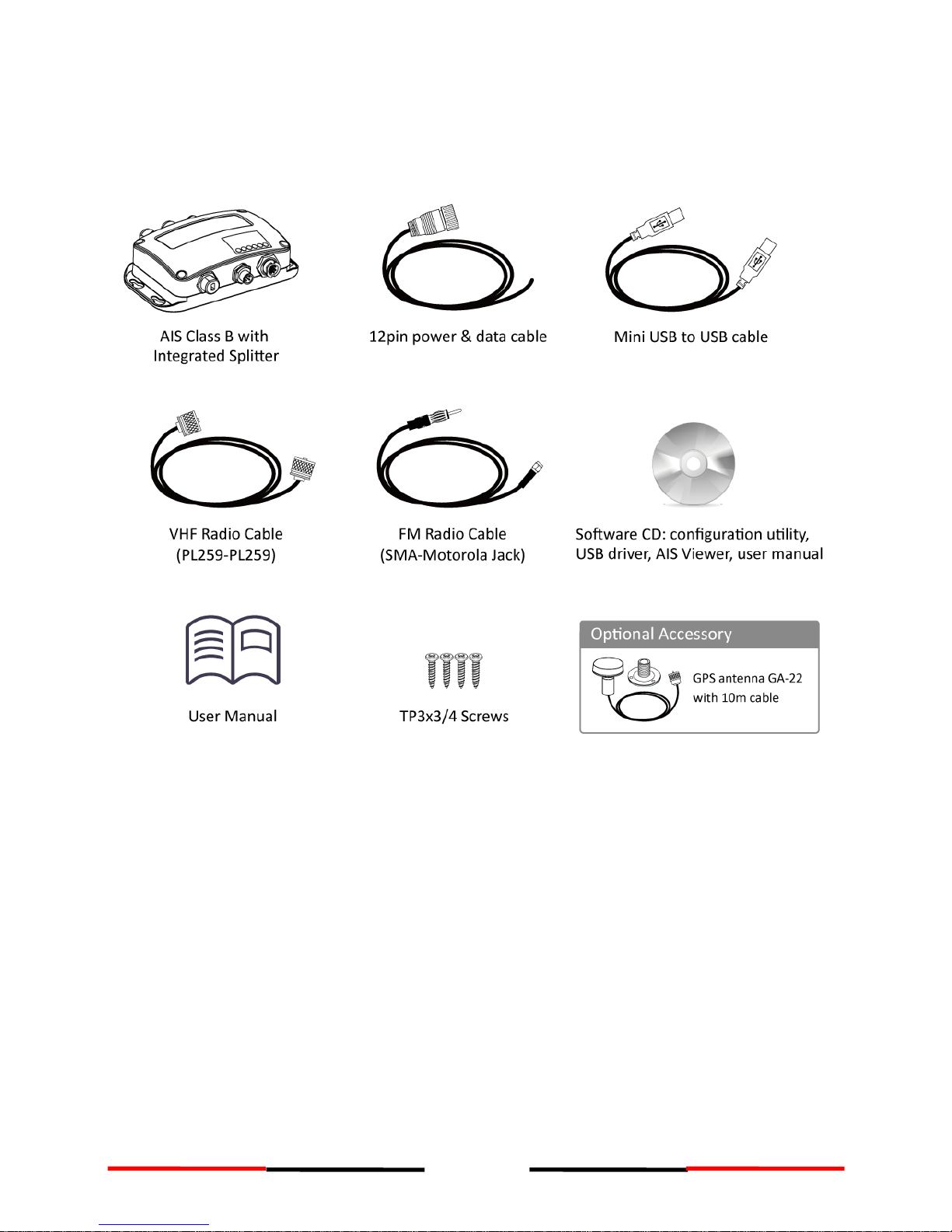
1.2 EQUIPMENTS IN THE BOX ........................................................................................................8
2INSTALLATION..................................................................................................................................... 9
2.1 INSTALLATION PROCEDURES.....................................................................................................9
2.2 MOUNTING THE MAIN UNIT .................................................................................................10
2.3 VHF ANTENNA INSTALLATION................................................................................................11
2.4 CONNECTING TO VHF RADIO ................................................................................................12
2.4.1 FM radio connection ....................................................................................12
2.5 GPS ANTENNA INSTALLATION ................................................................................................13
2.6 CONNECTING WITH NMEA 0183 DEVICES ..............................................................................14
2.7 AIS SILENT MODE CONNECTION ............................................................................................15
2.8 CONNECTION TO NMEA 2000 NETWORK ...............................................................................16
2.9 CONNECTING TO POWER SUPPLY ............................................................................................16
3CONFIGURING YOUR CAMINO-108S..........................................................................................17
3.1 CONNECTING TO YOUR AIS TRANSPONDER ...............................................................................17
3.1.1 Required Items.............................................................................................17
3.1.2 Installing “AIS Configuration Tool” ...............................................................17
3.1.3 Three steps to connect AIS transponder ......................................................18
3.1.4 Home page of the application......................................................................19
3.2 PROGRAMMING YOUR VESSEL DATA .........................................................................................20
4GET STARTED ....................................................................................................................................21
4.1 START UP CAMINO-108S...................................................................................................21
4.2 LED INDICATORS ................................................................................................................22
4.3 BUILT-IN INTEGRITY TEST (BIIT).............................................................................................23
4.4 AIS VIEWER DESCRIPTION ....................................................................................................23
4.5 CONNECTING YOUR CAMINO-108S TO MACINTOSH.................................................................23
5SPECIFICATIONS ...............................................................................................................................24
5.1 PRODUCT SPECIFICATIONS.....................................................................................................24
5.2 DIMENSIONS......................................................................................................................26
5.3 NMEA 2000 PGN INFORMATION.........................................................................................27
5.4 SUPPORTED NMEA 0183 SENTENCES ....................................................................................28
6TROUBLESHOOTING .......................................................................................................................29
7ABBREVIATIONS...............................................................................................................................31
8FCC INTERFERENCE STATEMENT ...............................................................................................32
9RF EXPOSURE WARNING ...............................................................................................................32
DECLARATION OF CONFORMITY.........................................................................................................33
AMEC WORLDWIDE WARRANTY.........................................................................................................33
APPENDIX: HOW TO DETERMINE SERIAL PORT ...........................................................................34

6
1System Overview
1.1 Product Description
CAMINO-108S is a smart combination of AMEC AIS Class B with our latest antenna
splitter. It allows you to share a single VHF antenna with VHF radio, which simplifies
installation and reduces cable runs.
The unit is designed to provide high performance and great reliability, resulting from
our year long field experience. It contains 1 VHF transmitter, 2 AIS receivers on 2 VHF
channels and 1 MCU with cutting edge software defined radio technology. Chart plotter
and PC can be integrated with ease over its NMEA2000, NMEA0183 or waterproof USB
port.
The built-in splitter featuring zero insertion loss on reception path and low insertion
loss on transmission path ensures optimized range of your VHF radio and AIS
transponder. The built-in test function gives a simple diagnosis in the event of antenna
problem and system failure. Its transparent mode guarantees priority to VHF radio
operation even if the splitter has power failure.
CAMINO-108S
Front Back

7
CAMINO-108S exchanges the following navigational data with other AIS equipped
vessels within VHF range to increase the safety of your journey at sea:
Static data:
Ship´s name
Call sign
MMSI
Ship type
Location of GPS antenna on the ship
Dynamic data:
Position of the vessel
Course over ground (COG)
Speed over ground (SOG)
True heading
It receives also safety related messages (SRM) from other vessels or persons who are in
distress.
AIS Class B transponder broadcasts ship´s static data every 6 minutes. Ship dynamic
data will be transmitted per following reporting interval:
Ship Speed
Nominal Reporting Interval
>2 knots
Every 30 seconds
≤2 knots or at anchored or moored
Every 3 minutes

8
1.2 Equipments in the Box
Upon receiving the product please verify items in the box. If any is missing, please
contact your local AMEC representative immediately.
Figure 1 Box Content

9
2Installation
2.1 Installation Procedures
Please familiarize the manual content before beginning the installation. Depending on
your hardware configuration, use the following recommended steps for installation.
1) Mount the transponder unit to an appropriate location
2) Install VHF antenna
3) Connect to VHF radio
4) Connect to FM radio
5) Install GPS antenna
6) Connect to a chart plotter via NMEA 0183 and/or other instruments
7) Connect to a chart plotter via NMEA 2000 and/or other instruments
8) Connect to a Tx switch box (optional)
9) Connect to an appropriate power source (12V / 24V DC, 2A)
Figure 2 Connection Diagram

10
2.2 Mounting the Main Unit
The following guidelines should be noticed when selecting the environment to install
your AMEC CAMINO-108S:
Do not install the device in a flammable or hazardous atmosphere such as in an
engine or generator room or close to fuel tanks.
Installation of the device should be undertaken in a safe environment without being
exposed to any splashing water or rain.
There should be adequate space around the device for routing of cables. See figure
below for details of the device dimensions.
The safe distance of the transponder to any magnetic compass is at least 0.55m.
The operating temperature is between -15°C and +55°C.
The device can be installed and mounted on flat surface, or it can be mounted on
wall with the four self tapping screws supplied.
The device should be mounted in a location where the indicators can readily be
observed as these indicators deliver relevant information on the status of the device.
Figure 3 Mounting the Transponder

11
2.3 VHF Antenna Installation
The quality and positioning of the antenna are the most important factors dictating AIS
performance. It is recommended that a VHF antenna with omnidirectional vertical
polarization be specifically tuned for marine band. Since the range of VHF signals is
largely decided by line of sight distance, the VHF antenna should be placed as high as
possible and at least 5 meters away from any constructions made of conductive
materials.
Figure 4 VHF Antenna Locations
The VHF antenna connector type on CAMINO-108S is SO239 which is designed to
work with a PL259 connector.
Figure 5 VHF Antenna Connector
Other transmitting
antenna
VHF Antenna
2m
10m
Other VHF Antenna
The recommended
vertical distance between
antennas is 2m.
The recommended
horizontal distance
between antennas is 10m.

12
2.4 Connecting to VHF Radio
Figure 6 VHF Radio Connector
It is important for users to make sure that the VHF radio is always connected to the VHF
radio input port (left SO-239 connector) –and never connected to antenna input port.
When VHF radio is connected to antenna input port, the AIS receiver of CAMINO-108S
might be severely damaged.
The internal path for VHF radio stays transparent also when CAMINO-108S is switched
off or has power failure. CAMINO-108S is designed to give priority to VHF radio in the
event of simultaneous transmission of VHF radio and AIS.
In case VHF radio is not connected to CAMINO-108S, the VHF radio connector should
stay floating or be connected with a 50ohm dummy load.
2.4.1 FM radio connection
Use the Motorola jack of the attached FM radio cable to connect to radio´s female
receptacle. For best FM radio reception, make sure the VHF antenna is extended to the
highest achievable position.
Figure 7 FM Radio Connector

13
2.5 GPS Antenna Installation
Install the GPS antenna where it has a clear view to the sky, so that it may access the
horizon freely with 360°degrees.
Figure 8 GPS Antenna Locations
It is recommended to keep the GPS antenna out of the transmitting beam of
high-power transmitters such as Inmarsat devices and radar.
When connecting the cables, take note of the following precautions.
Bending cables may cause damages to the inner wires and impair overall the
performances.
Each coaxial cable should be set up separately and can only be set up in a
single cable tube.
Insulation on connector port of the coaxial cable should be considered.
CAMINO-108S is tested with the GPS antenna GA-22. It’s recommended to use GA-22 to
ensure optimal reliability of your AIS system.
For pole mounting the GA-22, a 1 inch 14 TPI thread pole will be required.
Figure 9 GPS Antenna Mounting
Ensure a free 360˚
horizon with a vertical
observation of 5˚.
The recommended
horizontal distance
between GPS antennas
and other antennas is
3m.
5˚
3m

14
2.6 Connecting with NMEA 0183 Devices
CAMINO-108S supports two NMEA 0183 ports and external silent mode switch with its
12-pin data cable. The default NMEA 0183 baud rates are 38400-bps (high speed) and
4800-bps (low speed). User can change the baud rates using the provided configuration
utility. Typically the high speed setting is primarily for chart plotter connection, while
the low speed setting can be used for NMEA 0183 compatible instruments.
CAMINO-108S NMEA 0183 supports multiplexer function. Received NMEA 0183 data
from both ports will be multiplexed and forwarded to both NMEA 0183 output ports
and USB.
Figure 10 Wiring Instructions
Warning: During installation, you may have to peel off some wires to
make the appropriate connections. After completing the installation,
please cover all exposed wires with a rubber-vulcanized tape to prevent
the devices from malfunctioning or short-circuited.

15
2.7 AIS Silent Mode Connection
When Silent Mode is required, it is possible to connect an external toggle switch to
CAMINO-108S. Connect the toggle switch between the pink and light green (and/or
light blue) wires to enable Silent Mode function, as depicted in Figure 11. An optional
external Tx Switch Box (part number SB-181) is available from AMEC for silent mode
activation.
Figure 11 Silent Switch Connection

16
2.8 Connection to NMEA 2000 Network
The CAMINO-108S is equipped with NMEA 2000 interface with LEN=1. CAMINO-108S is
able to send AIS data and forward received GPS data (from internal GPS antenna) via
NMEA 2000 network to other NMEA 2000 devices. For further applications, please refer
to supported PGN in 5.3. An updated PGN list is available at AMEC website under FAQ
for CAMINO-108.
A compatible T-connector and drop cable available by your local service partner are
needed to connect the device to your chart plotter with NMEA 2000 interface:
Figure 12 NMEA 2000 Network
2.9 Connecting to Power Supply
The CAMINO-108S requires a 12V or 24V DC power supply (9.6 to 31.2V) capable of
supplying 2A peak current @12V DC. The red wire and the black wire on the 12 pin
cable are used to connect the power supply’s positive and negative terminals. Practically,
it is suggested to use a minimum 2A fuse before connecting directly to the
battery/power supply.

17
3Configuring Your CAMINO-108S
Your CAMINO-108S is delivered with a powerful “AIS Configuration Tool” allowing user
to set up the transponder and make a real-time diagnosis. A more detailed user guide of
configuration tool can be found in the “Help” of the software.
3.1 Connecting to your AIS Transponder
3.1.1 Required Items
Before preceding the configuration procedure, make sure the following items are
available:
USB Driver (included in the software CD)
USB cable (included in the box)
Mac OS X 10.6 and later or Microsoft® Windows® XP, Windows® Vista®, Windows
7, Windows 8, Windows 10 (including both 32 and 64-bit versions)
One available USB port on PC
Available CD-ROM drive on PC
Note: For configuration and firmware upgrade purpose, B600 series
can be powered only by USB. When USB power is in use, the device
will not transmit any data.
3.1.2 Installing “AIS Configuration Tool”
The “AIS Configuration Tool” must be installed before connecting your transponder to
your PC or Mac.
The application can be found on the CD supplied with your AIS Class B transponder.
Insert the CD into your PC or Mac and navigate to the ‘Windows’ or ‘Finder’ folder.
Windows: Double-click the ‘setup.exe’ item to start the installer and follow the
on-screen instructions.
Mac: Double-click the ‘AISConfigurationTool.dmg’ file. A new Finder window will
open and drag the “AIS Configuration Tool” to the Applications folder to complete
the installation process.
You can now launch the application from the Windows® Start menu or the Mac
Applications folder.

18
3.1.3 Three steps to connect AIS transponder
Step 1:
Connect your Class B AIS transponder to your PC or Mac using a USB cable. In most
cases the USB driver will be installed automatically by Windows system. When USB
driver installation is not done automatically, it can be found on the attached CD and
installed manually. Follow the on-screen instructions and assign the correct file path of
the USB driver to complete the installation. You can also install the USB driver via the
Device Manager in the Control Panel.
Step 2:
Select the “Com Port” corresponding to your AIS transponder from the drop down
menu at the top left of the application window, the Com Port will normally be listed as
“AIS Virtual Com”.
Step 3:
Click the ‘Connect’ button. In a short moment, the button will be displayed as
“Disconnect” when the connection is established.

19
3.1.4 Home page of the application
The application is now communicating with your AIS transponder and will display any
pre-configured vessel data on the ‘Home’ page depicted as follows.
Figure 13 Home Page of the Application

20
3.2 Programming your vessel data
After the device is successfully connected with the Configuration Tool, click on the
“Configuration” tab. You will require the following information in order to configure the
device:
•Vessel´s name: limited to 20 characters
•Call sign: limited to 7 characters
•MMSI: Enter your MMSI (Maritime Mobile Service Identity) number
•Vessel type: choose your ship type from the drop down list
•Ship dimensions: Enter the vessel dimensions by appointing the position of your
GPS antenna
•Configure NMEA 0183 Baud Rate: Baud rate of NMEA 0183 # 1 and NMEA 0183 # 2
can be configured here to 38400, 9600 or 4800.
WARNING: The MMSI number can only be entered once. Be sure to
enter the correct MMSI number, as it cannot be corrected if entered
incorrectly.
Figure 14 Static Data Setting
This manual suits for next models
1
Table of contents
Other AMEC Cables And Connectors manuals
Popular Cables And Connectors manuals by other brands

CONNECTGO
CONNECTGO CG049M manual

Heitronic
Heitronic 45601 Installation and operating instructions

QVS
QVS CEN36M Specification sheet

Microsoft
Microsoft High Definition AV Pack instruction manual

Toslink
Toslink 1x2 S/PDIF Quick installation guide

ROSE DISPLAYS
ROSE DISPLAYS CABLE AND CRIMP SLEEVES instruction sheet