AMEC CUBO-161 User manual


i
COPYRIGHT
The entire contents of this instruction manual, including any future updates, revisions,
and modifications, shall remain the property of AMEC at all times. Unauthorized
copies or reproduction of this manual, either in part or whole, in any form of print
and electronic media, is prohibited. The contents herein can only be used for the
intended purpose of this manual.
DISCLAIMER
AMEC is devoted to publish and maintain this product manual. As we continue to
improve our AIS products to satisfy all customers’ needs, information in this
document is subject to change without notice. AMEC does not make any
representations or warranties (implied or otherwise) regarding the accuracy and
completeness of this document and shall in no event be liable for any loss of profit or
any commercial damage, including but not limited to special, incidental,
consequential, or other damage.
Manual Version 1.0
User’s Manual

ii
WARNING!
WARNING: The AIS antenna splitter must be installed and operated in
conformity with the provided instructions in the manual in order to maximize
the device performance.
WARNING: The device should be used only together with an approved AIS
transponder or receiver.
WARNING: DO NOT DISASSEMBLE OR MODIFY THE EQUIPMENT. Improper
disassembly or modification could cause personal injury and will invalidate the
guarantee.
WARNING: While most of the installation can be performed by the owner or the
crew, a final commissioning can be done by your local agent/dealer when
needed or required. AMEC and the local agent/dealer will not bear any
responsibilities over any damages resulted from improper installation by
unauthorized agent/dealer.

iii
FOREWORD
AMEC thanks you for the purchase of your new CUBO-161 AIS antenna splitter.
CUBO-161 is strictly tested at the factory to meet the rigorous demands of the
marine environment. With proper installation, operation and maintenance, the
equipment will serve loyally and reliably at its optimum.
For sales, services, and technical supports, please contact your local AMEC
representatives or Alltek Marine Electronics Corp at sales@alltekmarine.com or
service@alltekmarine.com. You are always welcome to visit our website at
www.alltekmarine.com for new product status and company update.
Thank you again. Be safe.

iv

I
TABLE OF CONTENT
1SYSTEM OVERVIEW........................................................................... 1
1.1 PRODUCT DESCRIPTION......................................................................1
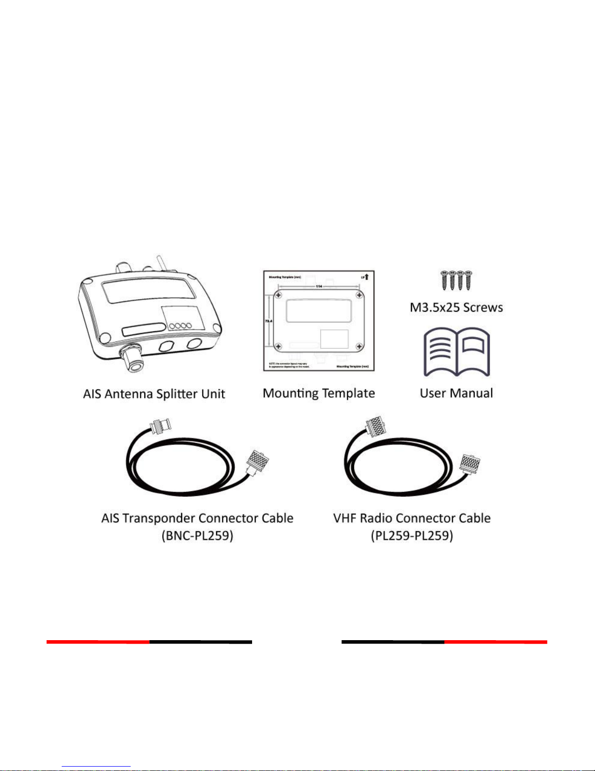
1.2 EQUIPMENTS IN THE BOX....................................................................2
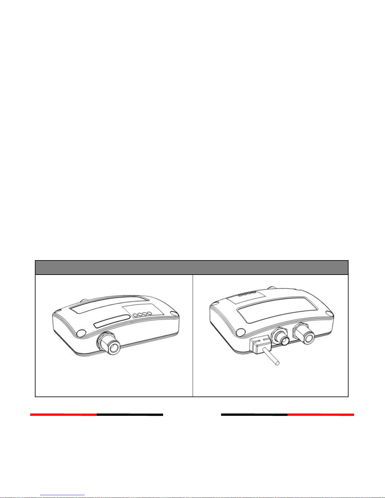
1.3 EXTERNAL CONNECTIONS ...................................................................3
1.4 WHAT IS AIS? .................................................................................4
2INSTALLATION ................................................................................... 6
2.1 INSTALLATION PROCEDURES ................................................................6
2.2 MOUNTING TRANSPONDER MAIN UNIT ................................................7
2.3 FM RADIO AND POWER SUPPLY CONNECTION ......................................10
3GET STARTED .................................................................................. 11
3.1 START UP THE TRANSPONDER ............................................................11
3.2 LED INDICATORS ............................................................................11
4SPECIFICATIONS .............................................................................. 12
4.1 PRODUCT SPECIFICATIONS ................................................................12
4.2 DIMENSIONS .................................................................................14
5TROUBLESHOOTING........................................................................ 15
FCC INTERFERENCE STATEMENT.............................................................. 16
RF EXPOSURE WARNING ........................................................................ 17
DECLARATION OF CONFORMITY ............................................................. 18
AMEC WORLDWIDE WARRANTY............................................................. 18

1
1System Overview
1.1 Product Description
CUBO-161 is AMEC´s latest AIS antenna splitter used to share a single VHF antenna
for both VHF radio and AIS transponder or receiver. It provides also a feed for FM
radio.
The design of the splitter enables zero insertion loss for maximized reception range of
your VHF radio and AIS device. It´s fail-safe feature guarantees priority to VHF radio
operation even if the splitter has power outage. The built-in test function gives a
simple diagnosis in the event of antenna problem.
Featured with durable design and compact housing, the CUBO-161 is the best
companion of your AIS transponder and receiver.
CUBO-161
Front
Back

2
1.2 Equipments in the Box
Upon receiving the product please verify items in the box. If any is missing, please
contact your local AMEC representative immediately.

3
1.3 External Connections

4
1.4 What is AIS?
The Automatic Identification System (AIS) is a Very High Frequency (VHF) radio
broadcasting system that transfers packets of data over the VHF data link (VDL) and
enables AIS equipped vessels and shore-based stations to exchange identification
information and navigational data. Ships with AIS transponders continually transmit
their ID, position, course, speed and other data to all nearby ships and shore stations.
Such information can aid greatly in situational awareness and provide a means to
assist in collision avoidance.
AIS equipment is standardized by ITU, IEC, IALA and IMO and is subject to approval by
a certification body. The following AIS devices have been developed for variant
applications.
AIS Class A:
mandated by the IMO for vessels of 300 gross tonnages and upwards engaged
on international voyages, cargo ships of 500 gross tonnages and upwards, as
well as passenger ships. It transmits typically on 12.5 watt output power.
AIS Class B:
provides limited functionality and is intended for non-SOLAS commercial
vessels and recreational vessels. It transmits typically on 2 watt output power.
AIS Receiver
only receives AIS signals from AIS class A, class B, AtoN and base station and
does not have transmitter to send out AIS signal.

5
AIS Base Station:
is provided by aids-to-navigation authorities to enable the ship to shore /
shore to ship transmission of information. Networked AIS Base Stations can
assist in providing overall maritime domain awareness.
AIS AtoN (Aids to Navigation):
provides an opportunity to transmit position and status of buoys and lights
through the same VDL, which can then show up on AIS-ready devices within
the range.
AIS SART:
Search and Rescue Transmitter using AIS can be used to assist in determining
the location of a vessel in distress. It is typically used on life rafts.

6
2Installation
2.1 Installation Procedures
Please familiarize the manual content before begin installation. Depending on your
hardware configuration, use the following recommended steps for installation.
1) Mount the splitter unit to an appropriate location
2) Connect the VHF antenna
3) Connect the VHF radio
4) Connect your AIS device
5) Connect an optional FM radio and appropriate power source (12V / 24V DC, 2A)
6) Perform LED checking and system functional test after the device is powered on

7
2.2 Mounting Transponder Main Unit
The following guidelines should be noticed when selecting the environment to install
your AMEC CUBO-161:
Installation of the splitter should be undertaken in a safe environment without
being exposed to any splashing water or rain.
Do not install the AIS antenna splitter in a flammable or hazardous atmosphere.
Keep adequate space around the AIS antenna splitter for routing of cables. See
figure below for device dimensions.
The safe distance of the splitter to any magnetic compass is at least 0.3m.
The operating temperature is between -15°C and +55°C.
The AIS antenna splitter can be installed and mounted on flat surface, or it can be
mounted on wall with the four self tapping screws supplied.
The device should be mounted in a location where the indicators can readily be
observed as these indicators deliver relevant information on the status of the AIS
antenna splitter.

8
Figure 1 Mounting the AIS antenna splitter

9
Use the attached cables to connect your VHF antenna, VHF radio and AIS transponder
or receiver as illustrated below:
Figure 2 Get your CUBO-161 connected

10
2.3 FM Radio and Power Supply Connection
Practically, it is suggested to use the fuse panel before connecting directly to the
battery/power supply. CUBO-161 requires a 12V or 24V power supply typically
provided by the vessel’s battery.
Figure 3 Wiring Instructions

11
3GET STARTED
3.1 Start up the Transponder
The AIS antenna splitter will start up whenever the connected power source is ON.
The operation status of the transponder can be checked from the LED lights on the
unit. Description of the LED indications is provided in the following section.
Please notice that VHF has priority when VHF radio and AIS transponder are
transmitting at the same time.
3.2 LED Indicators
Indicator
Light
Description
Power
Green
The green LED indicates that the transponder
has been powered up correctly.
Error
Red
The red LED illuminates when VHF is
transmitting over 25W, which indicates that
antenna has short or open circuit problem.
AIS
Green
The AIS transponder is transmitting
VHF
Green
The VHF radio is transmitting

12
4SPECIFICATIONS
4.1 Product Specifications
RF PERFORMANCE
AIS & VHF Radio Frequency Range
156.025 MHz~162.025 MHz
Insertion loss, AIS Receive path
Typical 0dB
Insertion loss, VHF Radio Receive path
Typical 0dB
Insertion loss, AIS Transmit path
Typical 2.0dB
Insertion loss, VHF Radio Transmit path
Typical 2.5dB
POWER SUPPLY
Supply Voltage
12V ~ 24V DC
Operating current (receive)
110mA typical at 12VDC
Operating current (transmit)
130mA typical at 12VDC
LED INDICATION
One Power Indicator
Green
One Error Indicator
Red
One AIS Transponder Transmission
Indicator
Green
One VHF Radio Transmission Indicator
Green

13
PHYSICAL
Width
128 mm (5.51 inch)
Height
36 mm (1.97 inch)
Depth
88 mm (7.87 inch) (exclude connector)
Weight
230 g
AIS port
BNC : Max. 12.5W, 50Ω
VHF Radio port
PL-259 : Max. 25W, 50Ω
Antenna port
PL-259
FM Radio
Wiring connection
ENVIRONMENT
Operating Temperature
-15°C~55°C
Storage Temperature
-25°C~70°C
Operating Humidity
95% RH at 40°C
Waterproof
IPX2

14
4.2 Dimensions
Table of contents
Other AMEC Cables And Connectors manuals