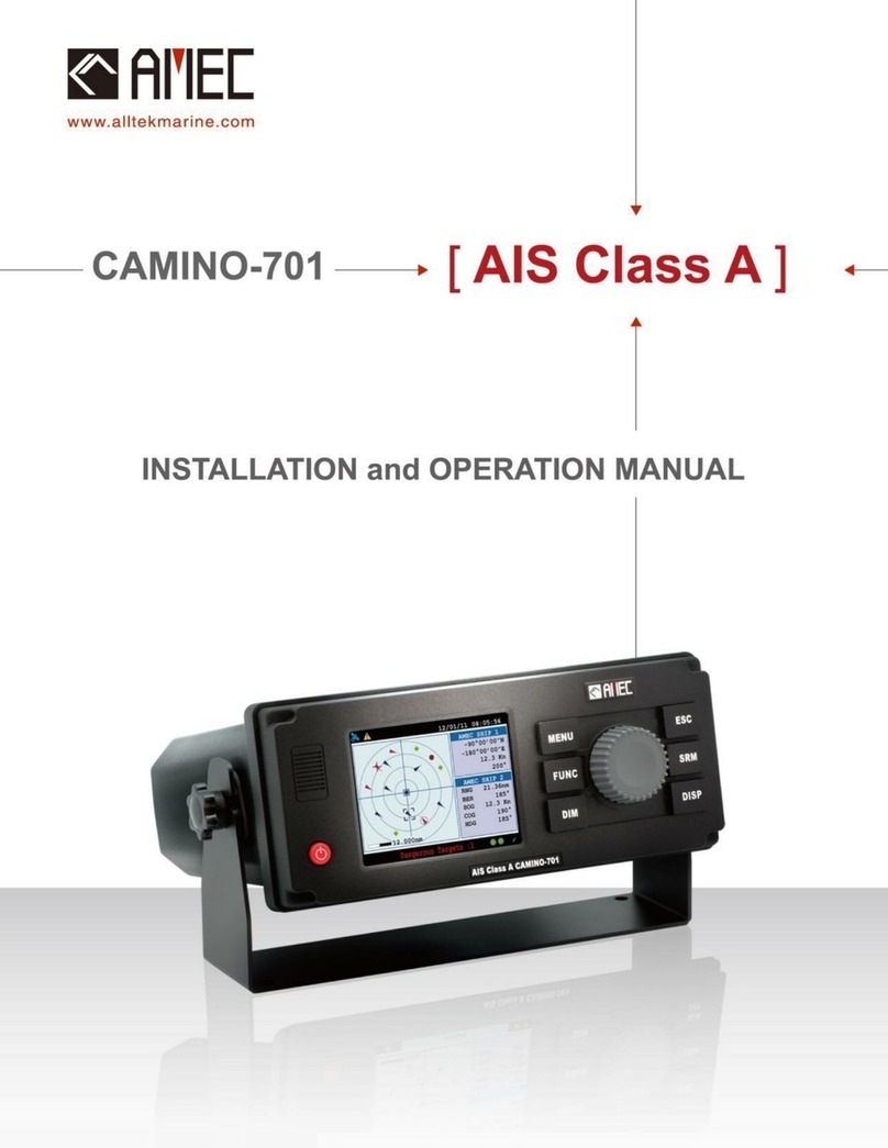
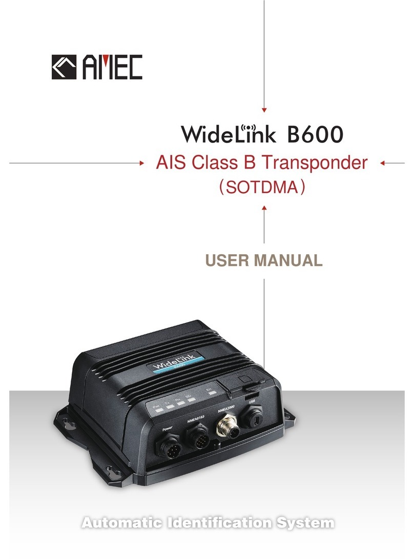
AMEC CAMINO-701 User manual

2

I
General Information Manual Edition 1.21
i. Copyright
The entire contents of this instruction manual, including any future updates, revisions, and
modifications, shall remain the property of AMEC at all times. Unauthorized copies or reproduction
of this manual, either in part or whole, in any form of print and electronic media, is prohibited. The
contents herein can only be used for the intended purpose of this manual.
ii. Disclaimer
AMEC is devoted to publish and maintain this product manual. As we continue to improve our AIS
products to satisfy all customers’ needs, information in this document is subject to change without
notice. AMEC does not make any representations or warranties (implied or otherwise) regarding the
accuracy and completeness of this document and shall in no event be liable for any loss of profit or
any commercial damage, including but not limited to special, incidental, consequential, or other
damage.
iii. Safety Warning
It is important to know that AIS is designed for the purpose of anti-collision and serves as a
complement to navigation. It is not the absolute navigational equipment and does not
replace any navigational system installed on board.
Any AIS device cannot guarantee monitoring and receiving signals from all vessels in the
surroundings unless those vessels are equipped with AIS devices.
The coastline map in this transponder is neither verified nor approved by Hydrographic
Authorities. It is not an Electronic Chart System and therefore should not be used for
navigation. The information provided by the coastline map is for reference only and should
be used together with other navigation sources and devices.
ELECTRICAL SHOCK HAZARD
Improper disassemble or modification could cause electrical shocks, fire, or personal injury.
Only qualified personnel could work on the interior of the equipment.
MAKE SURE THE POWER SOURCE AND THE POWER INPUT ARE MATCH
Incorrect power sources will damage the equipment and may even result in fire.
Please ensure the correct power input on the adaptor before installation.
AVOID DIRECT CONTACT WITH RAIN OR SPLASHING WATER
Electrical shock or fire could be resulted if water leaks into the equipment.
NOTE/INFORMATION
Important notices and information will be noted in this Installation and Operation Manual

II
iv. Product Category
This product is categorized as “protected” in accordance with the requirements as defined in IEC
60945.
v. Compass Safe Distance
Safe distance to the transponder (and junction box) unit is:
Standard-magnetic-compass: 0.50 m
Steering-magnetic-compass: 0.40 m
vi. Hardware / Software Version
Hardware version: A701-010
Software version: 1.0.6.41
The model name/number, hardware information, and firmware (software) version of the
transponder can be identified through MKD at MENU/DIAGNOSTICS/VERSION. The software
maintenance/upgrade of the transponder can be carried out on board via USB interface. The
onboard documentation as described in Appendix C can be used to assist reflecting software
maintenance records.
vii. Type Approval
The AMEC CAMINO-701 AIS transponder complies with applicable international standards and is
type approved in accordance with the European Marine Equipment Directive.
viii. Declaration of Conformity
Hereby, Alltek Marine Electronics Corp. (AMEC) declares that this CAMINO-701 is in compliance
with the essential requirements and other relevant provisions of Directive 96/98/EC.
ix. Disposal Instruction
Do not dispose of this device with unsorted waste.
Improper disposal may be harmful to the environment and human health. Please refer to your local
waste authority for information on return and collection systems in your area.
x. Contact Information
For sales, services, and technical supports, please contact your local AMEC representatives or Alltek
Marine Electronics Corp at www.alltekmarine.com or sales@alltekmarine.com or

i
Table of Contents
1WHAT IS AIS? .............................................................................................................1
2SYSTEM OVERVIEW....................................................................................................2
2.1 PRODUCT DESCRIPTION.................................................................................................................. 2
2.2 MAIN FEATURES .......................................................................................................................... 2
2.3 INTERCONNECTION DIAGRAM .......................................................................................................... 3
3INSTALLATION............................................................................................................4
3.1 EQUIPMENTS IN THE BOX................................................................................................................ 4
3.2 INSTALLATION PROCEDURES ............................................................................................................ 4
3.3 RF CABLE REQUIREMENTS .............................................................................................................. 5
3.4 VHF ANTENNA INSTALLATION ......................................................................................................... 5
3.5 GPS ANTENNA INSTALLATION.......................................................................................................... 6
3.6 MOUNTING CAMINO-701............................................................................................................ 6
3.6.1 Mounting Transponder..........................................................................................................6
3.6.2 Mounting Junction Box ..........................................................................................................8
3.6.3 Mounting Pilot Plug ...............................................................................................................9
3.7 EXTERNAL CONNECTORS (TRANSPONDER MAIN UNIT) ......................................................................... 11
3.8 EXTERNAL CONNECTORS (JUNCTION BOX)......................................................................................... 12
3.9 CONNECTING EXTENSION CABLE ..................................................................................................... 14
3.10 CONFIGURING CAMINO-701 ................................................................................................... 15
3.10.1 Initial Configuration .............................................................................................................15
4OPERATION.............................................................................................................. 17
4.1 PANEL DESCRIPTION.................................................................................................................... 17
4.1.1 Status Bar .............................................................................................................................18
4.1.2 Transmission and Reception Bar .........................................................................................19
4.2 DISPLAY MODES ........................................................................................................................ 20
4.2.1 Target Symbol Descriptions .................................................................................................21
4.2.2 Coastal View.........................................................................................................................23
4.2.3 Radar View ...........................................................................................................................24
4.2.4 Dimmer Setting ....................................................................................................................24
4.3 ENTERING TEXT.......................................................................................................................... 25
4.4 MENU TREE OVERVIEW ............................................................................................................... 27
4.4.1 How to access and use MAIN MENU ...................................................................................28
4.4.2 Menu Item Brief Description ...............................................................................................29
4.5 MESSAGES................................................................................................................................ 31
4.5.1 Inbox SRM ............................................................................................................................31
4.5.2 Outbox SRM .........................................................................................................................32
4.5.3 Broadcast SRM.....................................................................................................................32
4.5.4 Addressed SRM ....................................................................................................................33
4.5.5 Long Range SRM ..................................................................................................................34
4.6 INLAND MESSAGES ..................................................................................................................... 34
4.6.1 ETA/RTA Inbox .....................................................................................................................35
4.6.2 ETA Outbox ..........................................................................................................................35
4.6.3 Create ETA Message ............................................................................................................35
4.6.4 POB Outbox..........................................................................................................................36
4.6.5 Create POB Message............................................................................................................37
4.6.6 EMMA Warning....................................................................................................................37

ii
4.6.7 Water Level ..........................................................................................................................38
4.7 NAVIGATION STATUS................................................................................................................... 38
4.7.1 Own Ship ..............................................................................................................................39
4.7.2 AIS Targets ...........................................................................................................................40
4.7.3 Region List............................................................................................................................42
4.7.4 Alarm List .............................................................................................................................43
4.7.5 Alarm History .......................................................................................................................44
4.7.6 Sensor Status........................................................................................................................44
4.7.7 Dangerous List......................................................................................................................45
4.7.8 MOB List...............................................................................................................................46
4.7.9 Friend Ships..........................................................................................................................46
4.8 SHIP SETTING ............................................................................................................................ 47
4.8.1 Own Ship ..............................................................................................................................47
4.8.2 Voyage..................................................................................................................................48
4.8.3 CPA/TCPA .............................................................................................................................49
4.8.4 Set MMSI/IMO/ENI ..............................................................................................................49
4.8.5 Retry Times ..........................................................................................................................50
4.8.6 AIS Mode..............................................................................................................................51
4.9 INLAND SETTING......................................................................................................................... 51
4.9.1 Vessel Data Setting ..............................................................................................................52
4.9.2 ETA Setting ...........................................................................................................................52
4.9.3 Number of Person................................................................................................................53
4.9.4 Blue Sign Setting ..................................................................................................................53
4.9.5 Report Rate Setting..............................................................................................................53
4.10 TRANSCEIVER......................................................................................................................... 54
4.11 SYS CONFIG........................................................................................................................... 54
4.11.1 Customize.............................................................................................................................55
4.11.2 Radar View ...........................................................................................................................55
4.11.3 Map Calibration ...................................................................................................................56
4.11.4 Sensor Config .......................................................................................................................56
4.11.5 Factory .................................................................................................................................57
4.11.6 Password..............................................................................................................................57
4.11.7 Long Range Setting ..............................................................................................................58
4.11.8 Long Range Broadcast..........................................................................................................58
4.11.9 Destination Table Setting.....................................................................................................59
4.11.10 Alarms Setting..................................................................................................................59
4.11.11 VSWR Setting ...................................................................................................................60
4.12 DIAGNOSTICS......................................................................................................................... 61
5TECHNICAL SPECIFICATIONS..................................................................................... 64
5.1 APPLICABLE STANDARDS .............................................................................................................. 64
5.2 VHF TRANSCEIVER...................................................................................................................... 64
5.3 DSC RECEIVER........................................................................................................................... 64
5.4 GPS RECEIVER (INTERNAL) ........................................................................................................... 65
5.5 POWER SUPPLY.......................................................................................................................... 65
5.6 LCD DISPLAY ............................................................................................................................ 65
5.7 KEYPAD &KNOB ........................................................................................................................ 65
5.8 CONNECTION INTERFACE .............................................................................................................. 65
5.9 ENVIRONMENTAL ....................................................................................................................... 66
5.10 PHYSICAL.............................................................................................................................. 66
Other manuals for CAMINO-701
2
Table of contents
Other AMEC Marine Radio manuals

AMEC
AMEC Camino-101 Class B AIS User manual

AMEC
AMEC CAMINO-701 User manual

AMEC
AMEC CAMINO-701 User manual

AMEC
AMEC WideLink B600S User manual

AMEC
AMEC Camino-101 Class B AIS User manual

AMEC
AMEC Camino-108 User manual

AMEC
AMEC WideLink B600W User manual

AMEC
AMEC MANDO-301 User manual

AMEC
AMEC WideLink B600 User manual

AMEC
AMEC CAMINO-201 User manual