AMEC WideLink B600 User manual


3
COPYRIGHT
The entire contents of this instruction manual, including any future updates, revisions,
and modifications, shall remain the property of AMEC at all times. Unauthorized
copies or reproduction of this manual, either in part or whole, in any form of print and
electronic media, is prohibited. The contents herein can only be used for the intended
purpose of this manual.
DISCLAIMER
AMEC is devoted to publish and maintain this product manual. As we continue to
improve our AIS products to satisfy all customers’ needs, information in this
document is subject to change without notice. AMEC does not make any
representations or warranties (implied or otherwise) regarding the accuracy and
completeness of this document and shall in no event be liable for any loss of profit or
any commercial damage, including but not limited to special, incidental,
consequential, or other damage.
Manual Revision: Version 0.9
User’s Manual

4
WARNING!
WARNING: The transponder must be installed and configured in conformity with
the provided instructions in the manual by qualified installer in order to ensure
the device performance.
WARNING: It is the responsibility of the operator to handle the AIS device with
care. The device cannot replace human vigilance. Therefore it is important to
keep a diligent outlook at all times.
WARNING: Please bear in mind that not all vessels are equipped with AIS
transponders and therefore may not be visible to this transponder. Likewise,
certain conditions, such as device malfunction, the environment, improper use,
and overcrowded port traffic, may exist whereby the vessel equipped with this
AIS transponder is not visible to other AIS transponders.
WARNING: DO NOT DISASSEMBLE OR MODIFY THE EQUIPMENT. Improper
disassembly or modification could impair its performance and will invalidate the
guarantee.
FOR USERS IN THE UNITED STATES OF AMERICA ONLY
WARNING: It is a violation of the rules of the Federal Communications
Commission to input an MMSI that has not been properly assigned to the
end user, or to otherwise input any inaccurate data in this device.
★ The entry of static data into this device shall be performed by the vendor of
the device or by an appropriately qualified person in the business of installing
marine communications equipment on board vessels.
★ Instructions on how to accurately enter and confirm static data in the device
can be found in this user manual.
FOREWORD
We thank you for the purchase of your new WideLink B600, AIS SOTDMA class B
transponder. Wherever you sail now, you can have a better overview of your
surroundings at sea and voyage with more safety.
WideLink B600 is strictly tested to meet the rigorous demands of the marine
environment. With proper installation and use, the equipment will serve loyally and
reliably at its optimum.
For sales, services, and technical supports, please contact your local AMEC
representatives or Alltek Marine Electronics Corp at sales@alltekmarine.com or
service@alltekmarine.com. You are always welcome to visit our website at
www.alltekmarine.com for new product status and company update.
Thank you again. Be safe.

5
TABLE OF CONTENT
1SYSTEM OVERVIEW ........................................................................................................................... 6
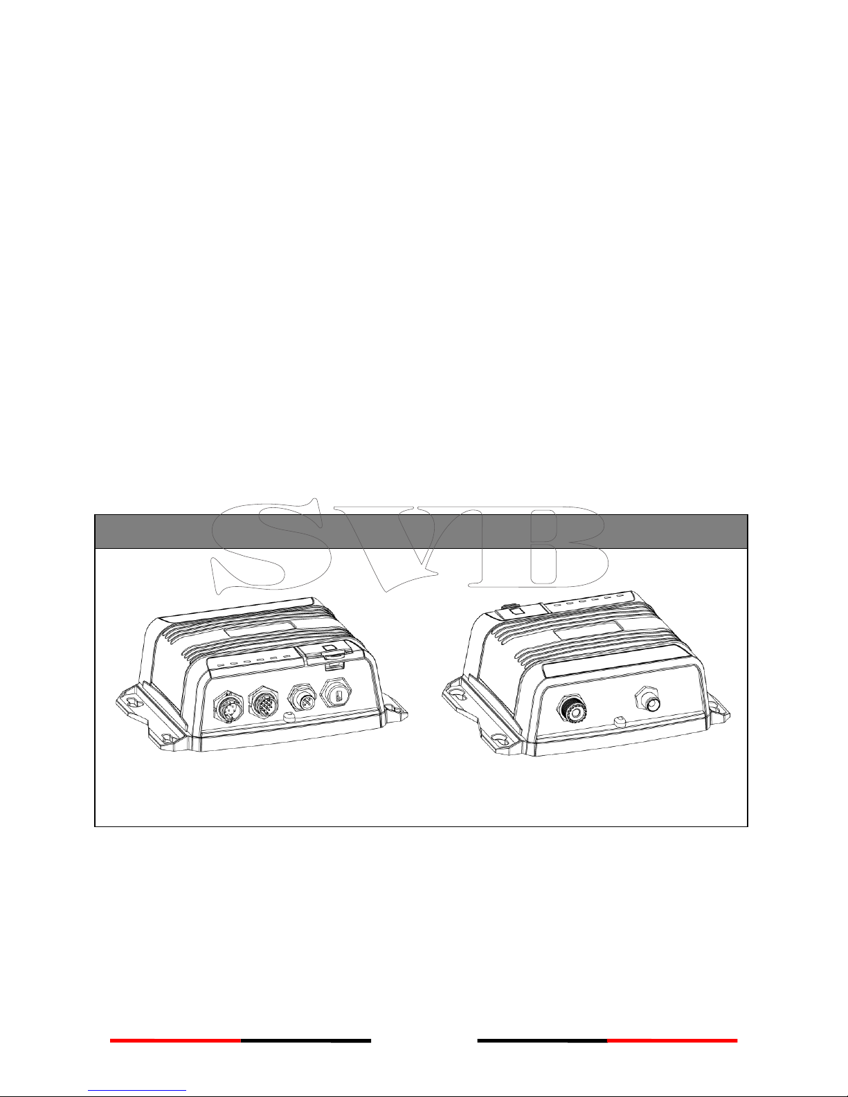
1.1 PRODUCT DESCRIPTION .........................................................................................................6
1.2 CLASS AVS.SOTDMA CLASS BVS.CSTDMA CLASS B...............................................................8
1.3 EQUIPMENT IN THE BOX .........................................................................................................9
2INSTALLATION.................................................................................................................................. 10
2.1 INSTALLATION PROCEDURES ..................................................................................................10
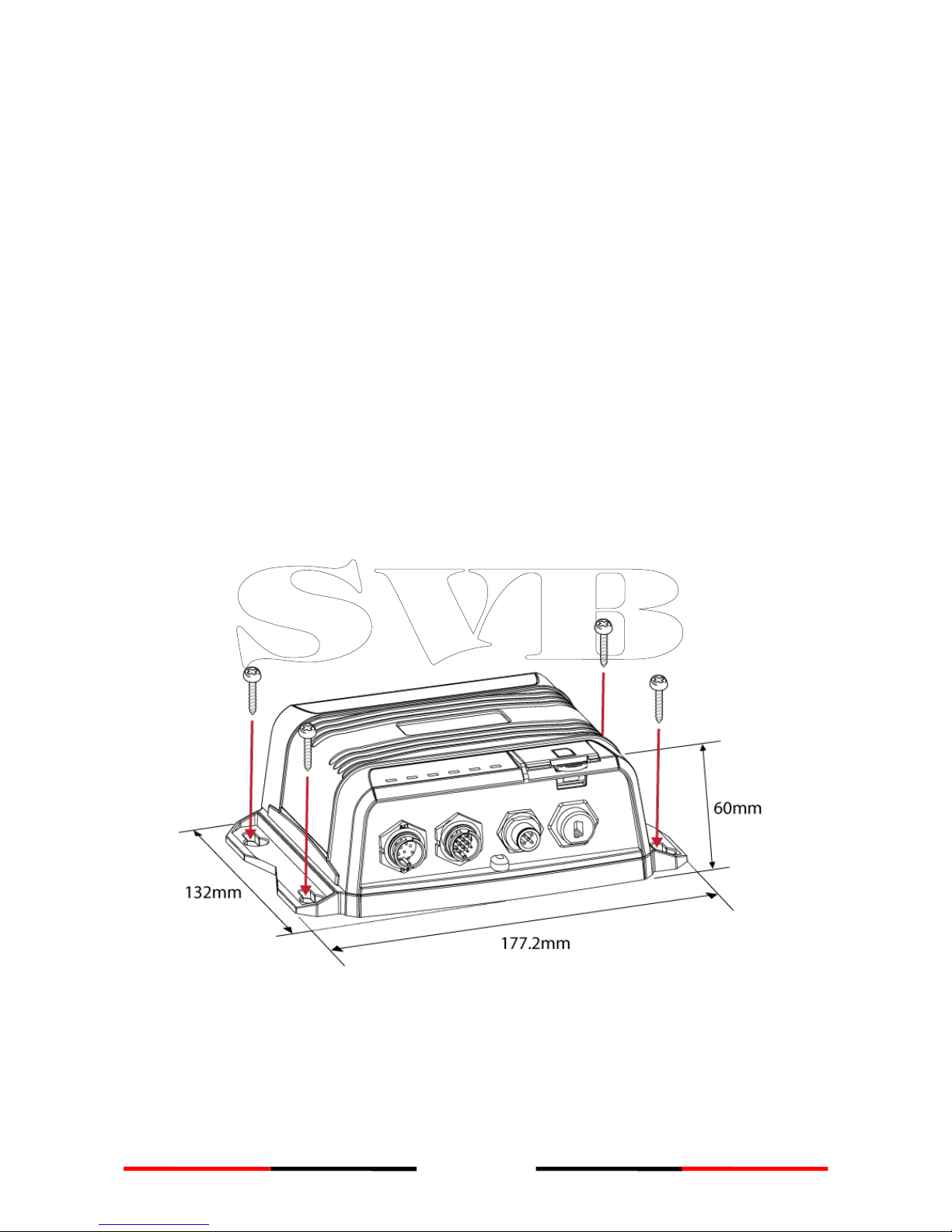
2.2 MOUNTING TRANSPONDER MAIN UNIT ..................................................................................11
2.3 VHF ANTENNA INSTALLATION ...............................................................................................12
2.4 GPS ANTENNA INSTALLATION................................................................................................13
2.5 CONNECTING WITH NMEA 0183 DEVICES ..............................................................................14
2.6 AIS SILENT MODE CONNECTION............................................................................................15
2.7 CONNECTION TO NMEA 2000 NETWORK...............................................................................15
2.8 CONNECTING POWER CABLE .................................................................................................16
2.8.1 Alarm Relay.....................................................................................................................17
3CONFIGURING YOUR WIDELINK B600 .................................................................................... 18
3.1 ESTABLISH CONNECTION TO PC..............................................................................................18
3.1.1 USB Driver Installation....................................................................................................18
3.1.2 Serial Port Connection ....................................................................................................19
3.1.3 Wireless Connection (only for WideLink B600W) ...........................................................19
3.2 PROGRAMMING YOUR VESSEL DATA.........................................................................................20
4GET STARTED.................................................................................................................................... 21
4.1 LED INDICATORS ................................................................................................................21
4.2 MICRO SD CARD DATA LOGGING ...........................................................................................22
4.3 WI-FI CONFIGURATION (WIDELINK B600W ONLY) ...................................................................23
4.3.1 Access Point Mode .........................................................................................................23
4.3.2 Client Mode ....................................................................................................................25
4.4 BUILT-IN INTEGRITY TEST (BIIT).............................................................................................26
4.5 AIS VIEWER DESCRIPTION ....................................................................................................26
4.6 INTRODUCING AMEC AIS APP .............................................................................................27
5SPECIFICATIONS .............................................................................................................................. 28
5.1 PRODUCT SPECIFICATIONS ....................................................................................................28
5.2 DIMENSIONS .....................................................................................................................30
5.3 NMEA 2000 PGN INFORMATION ........................................................................................31
5.4 SUPPORTED NMEA 0183 SENTENCES....................................................................................32
6TROUBLESHOOTING ...................................................................................................................... 33
7ABBREVIATIONS.............................................................................................................................. 35
8FCC INTERFERENCE STATEMENT .............................................................................................. 36
9RF EXPOSURE WARNING .............................................................................................................. 37
DECLARATION OF CONFORMITY........................................................................................................ 37
AMEC WORLDWIDE WARRANTY........................................................................................................ 38
APPENDIX: HOW TO DETERMINE SERIAL PORT .......................................................................... 39

6
1System Overview
1.1 Product Description
WideLink B600 is an SOTDMA AIS class B, the next evolution of AIS technology. Its 5W
transmit power, higher reporting rate and professional grade time division
management make B600 an overall more advanced product compared to AIS class B
based on CSTDMA scheme.
The globally approved transponder contains 1 VHF transmitter, 2 AIS receivers on 2
VHF channels and 1 MCU with cutting edge software defined radio technology. Its
internal GNSS receiver with 50 channels is able to process signals from GPS, Gallieo,
BeiDou and GLONASS with differential capability. It receives DSC, time-sharing with
AIS receivers.
Its enhanced housing with IPx7 waterproof and shock and temperature robustness is
ideal to survive harsh marine environments. Chart plotter and PC can be easily
integrated over its NMEA2000, NMEA0183 and waterproof USB port. Its built-in data
logger can record AIS data on micro SD card in the most intuitive way.
The integrated high performance Wi-Fi (WideLink B600W only) together with AMEC
AIS App makes your favorite smart phone or tablet a real-time AIS position plotter.
WideLink B600
Front Back
B600 exchanges the following navigational data with other AIS equipped vessels within
VHF range to increase the safety of your journey at sea:
Static data:
Ship´s name
Call sign
MMSI
Ship type

7
Location of GPS antenna on the ship
Dynamic data:
Position of the vessel
Course over ground (COG)
Speed over ground (SOG)
True heading
It receives also safety related messages (SRM) from other vessels or persons who are in
distress.
SOTDMA Class B AIS broadcasts ship´s static data every 6 minutes. Ship dynamic data
will be transmitted per following reporting interval:
Ship Speed
Nominal Reporting Interval
Increased reporting interval
>23 knots
Every 5 seconds
Every 15 seconds
between 14-23 knots
Every 15 seconds
Every 30 seconds
between 2-14 knots
Every 30 seconds
Every 30 seconds
≤2 knots or at anchored or
moored
Every 3 minutes
Every 3 minutes seconds
The Class B “SO” AIS follows the rules set by ITU-R M.1371-5, and increases the
reporting interval to “Increased Reporting Interval” in accordance with Table above
when less than 50 % of the slots of each of the last four consecutive frames are free.
When more than 65 % of the slots of each of the last four consecutive frames are free,
the Class B “SO” AIS reports at the “Nominal Reporting Interval”.

8
1.2 Class A vs. SOTDMA Class B vs. CSTDMA Class B
A brief comparison between class A and class B AIS is illustrated in the following table.
WideLink B600 is an SOTDMA class B AIS transponder.
Type of AIS
Class A AIS
Class B SOTDMA
Class B CSTDMA
Primary Access
Scheme
SOTDMA
(Self-organizing)
SOTDMA
(Self-organizing)
CSTDMA
(Carrier-Sense)
Standard
IEC 61993-2
IEC 62287-2
IEC 62287-1
Transmit Power
and range
12.5W
5W
2W
IMO Mandate
Mandatory for all
SOLAS vessels
No mandate
No mandate
Reporting rate
dynamic data
Highest (transmission
up to every 2 sec)
Higher (transmission
up to every 5 sec)
Low (transmission up
to every 30 sec)
AIS data
presented
Static, Dynamic,
Voyage
Static and Dynamic
data
Static and Dynamic
data
Applications
Commercial vessels,
fishing boats, working
boats, passenger
boats with more than
12 passengers
Smaller commercial,
fishing and work
boats, recreational
vessels
Recreational vessels
and small fishing
boats

9
1.3 Equipment in the Box
Upon receiving the product please verify items in the box. If any is missing, please
contact your local AMEC representative immediately.

10
2Installation
2.1 Installation Procedures
Please familiarize the manual content before installation. Depending on your
hardware configuration, use the following recommended steps to install the device.
1) Mount the transponder unit to an appropriate location
2) Install VHF antenna
3) Install GPS antenna
4) Connect to a chart plotter via NMEA 0183 and/or other instruments
5) Connect to a chart plotter via NMEA 2000 and/or other instruments
6) Connect to a Tx switch box and/or external alarm system(optional)
7) Connect to an appropriate power source (12V / 24V DC, 2A)
Figure 1 External Connections

11
2.2 Mounting Transponder Main Unit
The following guidelines should be noticed when selecting the environment to install
your AMEC WideLink B600:
Do not install the AIS transponder in a flammable or hazardous atmosphere such as
in an engine or generator room or close to fuel tanks.
Installation of the transponder should be undertaken in a safe environment
without being exposed to any splashing water or rain.
There should be adequate space around the AIS transponder for routing of cables.
See figure below for details of the AIS transponder dimensions.
The safe distance of the transponder to any magnetic compass is at least 0.3m.
The operating temperature is between -15°C and +55°C.
The AIS transponder can be installed and mounted on flat surface, or it can be
mounted on wall with the four self tapping screws supplied.
The device should be mounted in a location where the indicators can readily be
observed as these indicators deliver relevant information on the status of the AIS
transponder.
Figure 2 Mounting the transponder

12
2.3 VHF Antenna Installation
The quality and positioning of the antenna are the most important factors dictating
AIS performance. It is recommended that a VHF antenna with omnidirectional vertical
polarization be specifically tuned for AIS operation band. Since the range of VHF
signals is largely decided by line of sight distance, the VHF antenna should be placed
as high as possible and at least 5 meters away from any constructions made of
conductive materials.
Figure 3 VHF antenna locations
The VHF antenna connector type on WideLink B600 is SO239 which is designed to
work with a PL259 connector.
The recommended
horizontal distance
between antennas is 10m.
Other transmitting
antenna
VHF Antenna
2m
10m
Other VHF Antenna
The recommended
vertical distance between
antennas is 2m.

13
2.4 GPS Antenna Installation
Install the GPS antenna where it has a clear view to the sky, so that it may access the
horizon freely with 360° degrees.
Figure 4 GPS antenna locations
It is recommended to keep the GPS antenna out of the transmitting beam of
high-power transmitters such as Inmarsat devices and radar.
When connecting the cables, take note of the following precautions.
Bending cables may cause damages to the inner wires and impair overall the
performances.
Each coaxial cable should be set up separately and can only be set up in a
single cable tube.
Insulation on connector port of the coaxial cable should be considered.
WideLink B600 is tested and certified with the GPS antenna GA-22. It’s recommended
to use GA-22 with B600 series to ensure optimal reliability of your AIS system.
For pole mounting the GA-22, a 1 inch 14 TPI thread pole will be required.
Figure 5 Mounting GPS Antenna
Ensure a free 360˚
horizon with a vertical
observation of 5˚.
The recommended
horizontal distance between
GPS antennas and other
antennas is 3m.
5˚
3m

14
2.5 Connecting with NMEA 0183 Devices
WideLink B600 supports two NMEA 0183 ports and external silent mode switch with
its 12-pin data cable. The default NMEA 0183 baud rates are 38400-bps (high speed)
and 4800-bps (low speed). User can change the baud rates using the provided
configuration utility. Typically the high speed setting is primarily for chart plotter
connection, while the low speed setting can be used for NMEA 0183 compatible
instruments.
WideLink B600 NMEA 0183 supports multiplexer function. Received NMEA 0183 data
from both ports will be multiplexed and forwarded to all output ports as well as USB
and Wi-Fi (B600W only).
Figure 6 NMEA 0183 Connection

15
2.6 AIS Silent Mode Connection
When Silent Mode is required, it is possible to connect an external toggle switch to
WideLink B600. Connect the toggle switch between the purple and brown wires to
enable Silent Mode function, as depicted in Figure below. An optional Tx Switch Box
(part number SB-181) is available from AMEC for Silent Mode activation.
Figure 7 Silent Switch connection
2.7 Connection to NMEA 2000 Network
The WideLink B600 is equipped with NMEA 2000 interface with LEN=1. WideLink B600
is able to send AIS data and forward received GPS data (from NMEA 0183) via NMEA
2000 network to other NMEA 2000 devices. For further applications e.g. heading
sensor connection, please refer to supported PGN in 5.3. An updated PGN list is
available at AMEC website under FAQ for WideLink B600.
A compatible T-connector and drop cable/spur available by your local service partner
are needed to connect the class B transponder to your chart plotter with NMEA 2000
interface:
Figure 8 NMEA 2000 Network

16
2.8 Connecting Power Cable
Connect the WideLink B600 to vessel´s power source as illustrated below.
The WideLink B600 requires a 12V or 24V DC power supply (9.6 to 31.2V) capable of
supplying 2A peak current. Always use a minimum 3A fuse panel before connecting
directly to battery or power supply. Power on the power source will turn on the
transponder unit automatically.
B600´s power cables are marked with bullet connectors. Disconnect the transponder
from power source will shut down the unit immediately.
Figure 9 Power and alarm Connection

17
2.8.1 Alarm Relay
WideLink B600 supports internal alarm relay with its 8-pin power cable. Connect the
alarm relay to an audible alarm device or the ships alarm system, if available.
The maximum switching current is 1 A.
The maximum switching voltage is 250 VAC, 220 VDC.
Signal
Function
ALARM COM (Red)
Alarm relay common
ALARM NC (Orange)
Alarm relay normally closed
ALARM NO (Blue)
Alarm relay normally open

18
3Configuring Your WideLink B600
The AMEC AIS Configuration software enables users to set up the transponder by
entering own ship’s information. It also provides useful tools to monitor and diagnose
the transponder. A more detailed user guide of Configuration software can be found
in the “Help” menu of Configuration Utility.
To install the configuration software, open the AMEC AIS Configuration file on the CD
and click on the setup icon to start the installation process. Follow the on-
screen instructions to complete the installation and check the checkbox to start the
AMEC AIS Configuration Software at the end of the installation.
3.1 Establish Connection to PC
3.1.1 USB Driver Installation
Before preceding the configuration procedure, make sure the following items are
available:
Required Items
USB Driver (included in the software CD)
USB cable (included in the box)
PC/Laptop with Windows operating system (not included). WideLink B600 USB
Driver supports Windows XP, Windows Vista, Windows 7, Windows 8/8.1 and
Windows 10.
One available USB port on PC/Laptop
Available CD-ROM drive on PC/Laptop
The USB driver has to be installed before linking the transponder to your PC. Power on
the transponder and connect it to PC with the attached USB cable. A new hardware
found prompt will show up. In most cases the USB driver will be installed
automatically by Windows system.
When USB driver installation is not done automatically, user can also manually install
the USB driver which can be found on the attached CD. Follow the on screen
instructions and assign the correct file path of the USB driver to complete the
installation. You can also install the USB driver via the Device Manager in the Control
Panel.

19
3.1.2 Serial Port Connection
After the USB driver is installed and the transponder is recognized as a “Virtual Com
Port”, launch the Configuration Software, select Option in the menu bar, then
Connection, and “serial port”. There are 2 options to connect the software with your
transponder:
Auto: The system will scan all connected ports and their available baud rates
and establish connection automatically.
Manual: Configure baud rate and port manually. The default baud rate is
115200. To determine serial port with which the transponder is connected,
please refer to Appendix in this manual.
Click on “Connect”,to connect the Configuration Software with your transponder.
Figure 10 Serial port connection
3.1.3 Wireless Connection (only for WideLink B600W)
Figure 11 Wi-Fi connection for WideLink B600W
For WideLink B600W, the connection between the Configuration Software and your
transponder can also be established wirelessly. Please refer to 4.4 “Wi-Fi
Configuration” about how to access WideLink B600W from your PC as Access Point.
After your PC is wirelessly connected with the transponder, go to Option in the menu
bar, then Connection, and “Wi-Fi”. The IP address and Port are already
preprogrammed to fit WideLink B600W´s configuration. Click on “Connect”,to
connect the Configuration Software with your transponder.

20
3.2 Programming your vessel data
After the transponder is successfully connected with the Configuration Software, click
on the “STATIC DATA” tab. You will require the following information in order to
configure your AIS transponder:
•Vessel´s name: limited to 20 characters
•Call sign: limited to 7 characters
•MMSI: Enter your MMSI (Maritime Mobile Service Identity) number
•Ship type: choose your ship type from the drop down list
•Ship dimensions: Enter the vessel dimensions by appointing position of your GPS
antenna
WARNING: The MMSI number can only be entered
once. Be sure to enter the correct MMSI number, as it
cannot be corrected if entered incorrectly.
Figure 12 Static Data Setting

21
4GET STARTED
The transponder starts up whenever the connected power source is ON. It will
operate automatically when the transponder has been properly configured and
GPS/VHF antennas are properly installed. The transponder transmits its own ship
positions depending on vessel´s moving speed and should receive information of
other vessels in the vicinity.
The operation status of the transponder can be observed with the LED lights on the
unit. Description of the LED indications is provided in the following section.
4.1 LED Indicators
Indicator
Light
Description
Power
Green, steady
The transponder has been powered up correctly.
Tx / Silent
Green, flashing
The transponder is transmitting AIS data. The
flashing interval varies depending on vessel speed.
Orange, steady
The transponder is in silent mode, no AIS
transmission at all.
Orange, flashing
The transponder is acquiring a GPS fix, no AIS
transmission during this time period.
This can be the following situation:
The device is just newly powered on and is
acquiring a GPS position fix prior to
transmitting its first vessel information
report. This process may take several
minutes.
The GPS position fix has been lost. The
device is attempting to re-acquire
position fix for 30 minutes before entering
a BIIT system error state.
Rx
Green, flashing
The transponder is receiving AIS data.
SD
Green, flashing
SD card is being accessed.
Green, steady
SD card is full. Replace with another empty SD card
or delete files to obtain free spaces.
Wi-Fi (B600W)
Green, flashing
The green LED indicates an active Wi-Fi traffic
Error
Red, steady
MMSI is not properly programmed
Red, flashing
The transponder detected a BIIT system error
referring to chapter 4.4
Table of contents
Other AMEC Marine Radio manuals

AMEC
AMEC CAMINO-201 User manual

AMEC
AMEC CAMINO-701 User manual

AMEC
AMEC WideLink B600W User manual

AMEC
AMEC Camino-108 User manual

AMEC
AMEC Camino-101 Class B AIS User manual

AMEC
AMEC CAMINO-701 User manual

AMEC
AMEC CAMINO-701 User manual

AMEC
AMEC Camino-101 Class B AIS User manual

AMEC
AMEC MANDO-301 User manual

AMEC
AMEC WideLink B600S User manual