Amerec DESIGNER S Series User manual

4211-82 01-27-2020 7014132 314 SKSM 104 P
INSTALLATION AND OPERATING INSTRUCTIONS Page 1
WARNING
SECTION 1: GENERAL INFORMATION
These heaters are ETL approved by Intertek for permanent installations and
electrical connections. Built with splash proof construction, the conducting
parts are protected against water. All wiring must be performed in
accordance with local codes. See Diagram 2 for wire and room size
requirements.
Do not take a sauna if using
alcohol, drugs or medications.
Pregnant women or persons
with poor health should
consult their physician before
using any sauna.
Caution re hazard: Do not use
the sauna room for drying
clothes, bathing suits, etc. Do
not hang towels above heater
or place any object other than
the rocks supplied on the
heater. If any darkening of the
wall around the heater is
noticed discontinue sauna use
immediately.
Inspect sauna regularly for
required maintenance to
heater, control and benches.
Replace wood surfaces which
show any signs of
deterioration.
The heater gets extremely hot
during operation and should
not be touched or burns may
result.
Minors should be adequately
supervised whenever near a
hot or warming sauna.
"DESIGNER S" SERIES SAUNA HEATERS
MODELS 4.5S,6.0S,8.0S
(Model #'s 1712-45-0204, 1712-60-0204,1712-80-0204)
(With separate control, -3 designates 3 Phase.)
Read all instructions carefully before installation. Please leave all
instructions and warranty with the owner.
WARNING
Prolonged exposure to elevated temperatures is capable of inducing
hyperthermia. Hyperthermia occurs when the internal temperature of the
body reaches several degrees above the normal body temperature of
98.6°F. The symptoms of hyperthermia include an increase in the normal
temperature of the body, dizziness, lethargy, drowsiness, and fainting. The
effects of the hyperthermia include failure to perceive heat, failure to
recognize the need to exit the room, unawareness of impending hazard,
fetal damage in pregnant women, physical inability to exit the room and
unconsciousness.
WARNING
The use of alcohol, drugs, or medication is capable of greatly increasing
the risk of fatal hyperthermia.
0
10
20
30
40
50
1
7
654
3
2
10
9
8
0
SET TIMER
SET TEMPERATURE
Sauna Heating
Room Light
TEMPERATURE
CONTROL
MODEL 19-8
Listed
Sauna heater
No. 339 B
U
L
R

4211-82 01-27-2020 7014132 314 SKSM 104 P
INSTALLATION AND OPERATING INSTRUCTIONS Page 2
DIAGRAM 2
Note 1: Use separate 120V branch circuit protected for 15 or 20 amps if control light switch is to be used.
DIAGRAM 1
MOUNTING BRACKET LOCATION AND TO MINIMUM DISTANCE TO COMBUSTIBLE MATERIAL
Recheck your distances from the heater to
combustible materials to be sure you have the
proper minimum distances.
C
High Limit Control
D
2"
1"
18½"
74"
Minimum
Screws
6"
14 3/8" B
10½"
Use the long screws in the upper
holes of the mounting bracket
A
6½"
Min.
Temperature
Sensor
44"
Minimum
Guard
Rail
(Upper Bench)
K
"A"
DISTANCE
"B"
DISTANCE
"C"
DISTANCE
"D"
DISTANCE
"K"
DISTANCE
DESIGNER 4.5S 3.0" 3 5/8" 4.0" 10 3/4" 23"
DESIGNER 6.0S 4.0" 4 5/8" 5.0" 10 3/4" 23"
DESIGNER 8.0S 5.0" 5 5/8" 6.0" 11 1/2" 23"
HEATER
MINIMUM
OBSERVING MINIMUM DISTANCES IS
REQUIRED TO REDUCE FIRE HAZARD
Floor
Area
Wall
Height
Volume
Cu.Ft.
Wall
Height
Volume
Cu.Ft.
Power Supply
to Heater
Heater to
Control
1 120/208 21.6 2 #10AWG+N+GR 4 AWG #14+GR
1 120/240 18.8 2 #10AWG+N+GR 4 AWG #14+GR
3 120/208 12.5 3 #12AWG+N+GR 4 AWG #14+GR
3 120/240 10.8 3 #12AWG+N+GR 4 AWG #14+GR
1 120/208 28.8 2 #8AWG+N+GR 4 AWG #14+GR
1 120/240 25 2 #10AWG+N+GR 4 AWG #14+GR
3 120/208 16.7 3 #12AWG+N+GR 4 AWG #14+GR
3 120/240 14.4 3 #12AWG+N+GR 4 AWG #14+GR
1 120/208 38.5 2 #8AWG+N+GR 4 AWG #14+GR
1 120/240 33.3 2 #8AWG+N+GR 4 AWG #14+GR
3 120/208 22.2 3 #10AWG+N+GR 4 AWG #14+GR
3 120/240 19.2 3 #10AWG+N+GR 4 AWG #14+GR
HEATER MODEL
/ Product Number
KW
MINIMUM ROOM
MAXIMUM ROOM
DESIGNER 8.0S
(-3 = 3 Phase)
1712-80-0204
8
31 sq.
ft.
74"
DESIGNER 6.0S
(-3 = 3 Phase)
1712-60-0204
6
21 sq.
ft.
74"
DESIGNER 4.5S
(-3 = 3 Phase)
1712-45-0204
4.5
12 sq.
ft.
74"
175
96"
310
250
96"
425
Power Supply
to Control
Light Circuit
S
E
E
N
O
T
E
1
B
E
L
O
W
96"
210
WIRE SIZE
PHASE
VAC
AMPS
100
CAUTION: Avoid re, Do Not Place Combustible Material on sauna heater / ATTENTION:
Evitez les Incedies, Ne Placez Aucne Matiere Combustible Sur Lle Chauffe-saun
All wiring for sauna system or accessories should
be routed inside the walls or away from the high
temperature air from the sauna heater.

4211-82 01-27-2020 7014132 314 SKSM 104 P
INSTALLATION AND OPERATING INSTRUCTIONS Page 3
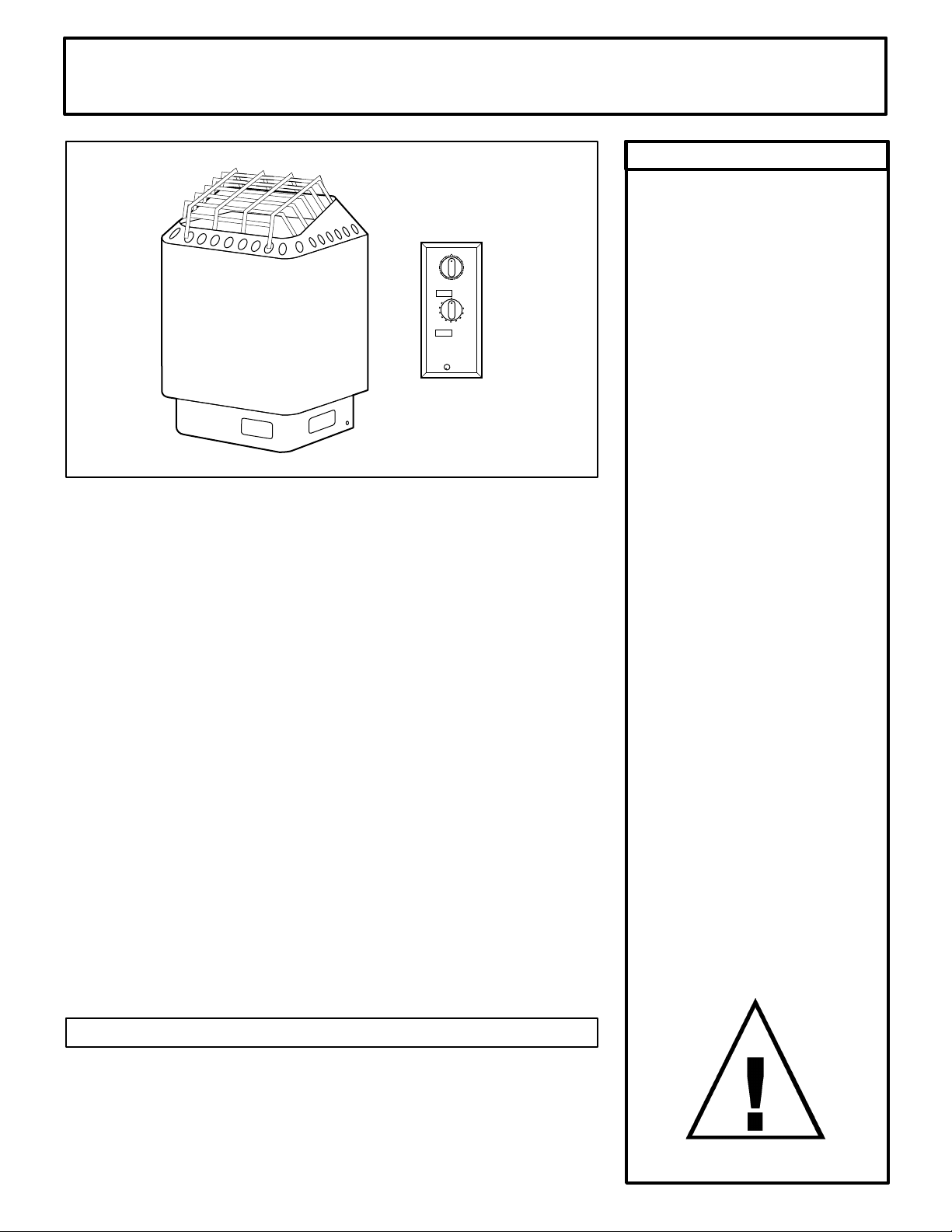
WARNING
SECTION 2: MOUNTING OF SAUNA HEATER
SECTION 3: PLACING OF ROCKS (SEE DIAGRAM #10)
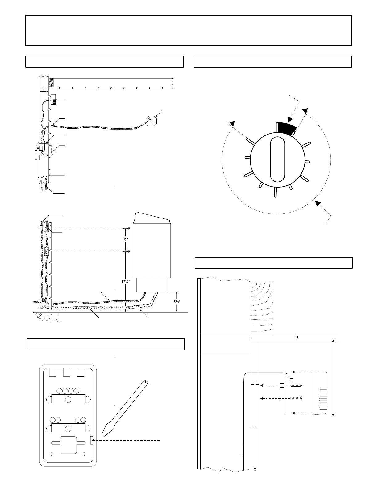
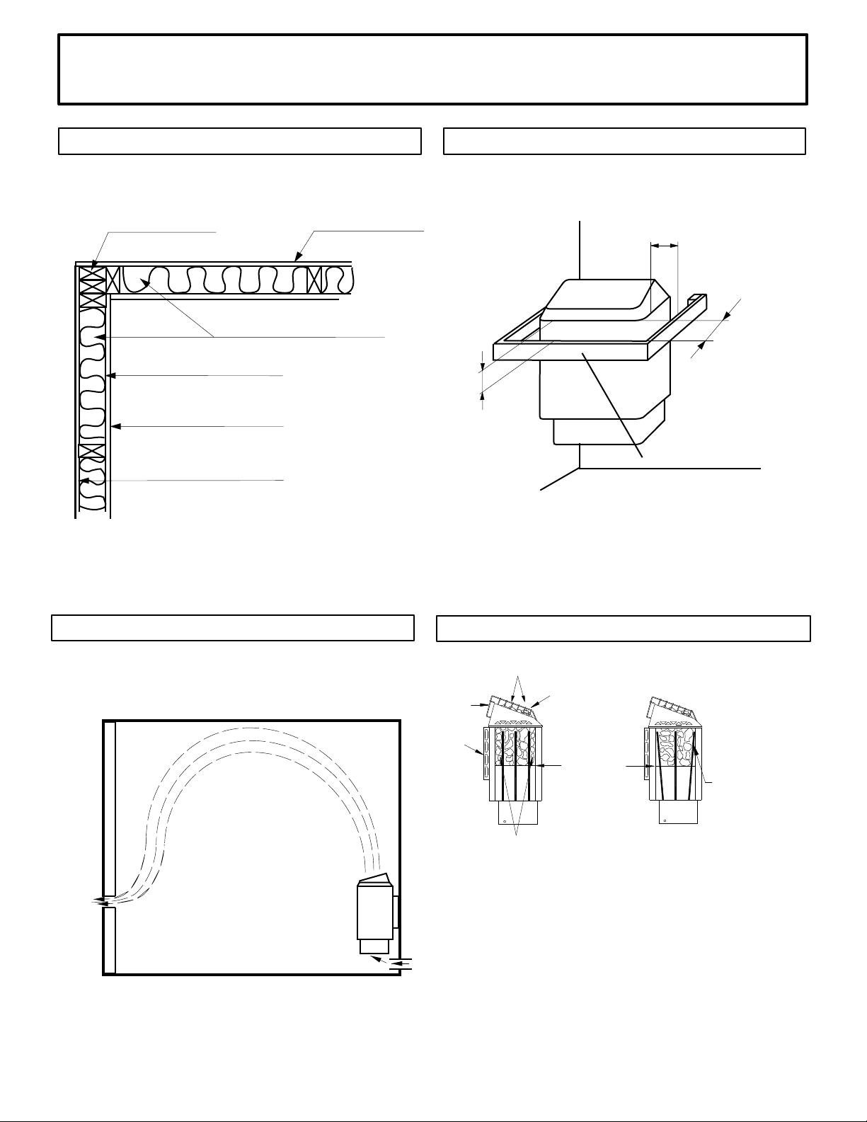
HANGING THE HEATER Using the template provided, drill four 9/64" holes
to fasten the heater to the wall. Install two ¼" x 1 ½" hex head lag screws
(supplied with the heater) into the upper two holes. Tighten these screws
until their heads are about 1/8" from the wall surface. The screws must be
threaded through the wall into a framing member or backing board to
support the heater weight. Hang the heater on the two upper screws.
Locate the two ¼" x 1" hex head lag screws (supplied with the heater) then
install them into the two lower mounting holes. Tighten to lock the heater in
place. See Diagram 1 for the heater location details and the necessary
clearances to combustible materials.
The rocks supplied with the heater have been chosen to provide the best
heater performance. Use of any other type of rock may void the heaters
warranty. Never operate the heater without rocks in place! Rinse the rocks
with water before placing in the heater. Carefully place the rocks loosely so
that the air can circulate through the heater. Packing the rocks too tightly
may cause the heater high limit switch to trip. The rocks must fully cover
the heating elements. Attach the guard with the screws provided.
Fire sprinkler systems used
inside any sauna room should
be properly rated for sauna
room temperatures.
Do not pour chlorinated pool
or spa water on heater.
Excessive water use on heater
may cause damage and void
warranty.
Electric Shock Hazard - High
voltage exists within this
equipment. There are no user
serviceable parts in this
equipment. All installation and
service to this equipment
should be performed by
qualied licensed personnel in
accordance with local and
national codes.
Do not construct sauna room
so as to restrict air ow
through the bottom of the
heater.
Packing the rocks too tightly
may cause the heater high
limit switch to trip.
SECTION 4: ELECTRICAL HOOK-UP
SECTION 6: HEATER SCREEN (GUARD RAIL)
Electrical installation must be made by a licensed electrician in accordance
with the National Electrical Code and local regulations.
Remove the screws from the left and right sides of the electrical box.
Remove the painted trim piece from the front of the box. Route the feed
wires through the holes provided in the bottom of the heater and connect
the wires to the terminal block. To determine the correct wire size, refer to
Diagram 2. Use copper supply wire only, suitable for minimum 90 degrees
C. The heater must be grounded! See Diagram 6 for proper connections.
Install a wooden heater guard to prevent the sauna bather from accidentally
touching the sauna heater. Install the heater guard rail with the dimensions
shown in Diagram 8.
SECTION 5: TEMPERATURE SENSOR
Feed the "low voltage" sensor wire from the control to the sensor location.
Sensor wire must be routed completely separate (as per low voltage
electrical wiring codes) from any wiring carrying over 50 volts. It may be
necessary to drill holes to string the wire through the studs or ceiling joists.
Route wires into control box and connect to terminals #2 and #3 at the
thermostat terminal block. Using a at tip screwdriver, unsnap sensor cover
from sensor. Mount sensor to nished wall directly above heater ve (5)
inches down from ceiling using two (2) screws (provided) as shown in
diagrams 1,3 & 5.

4211-82 01-27-2020 7014132 314 SKSM 104 P
INSTALLATION AND OPERATING INSTRUCTIONS Page 4
DIAGRAM 3 DIAGRAM 4
OFF ON
1
2
3
4
5
6
7
8
9
ONE HOUR OPERATING ZONE FOR 9 HOUR DELAY TIMER
This area from "OFF" to "ON" is the operating zone. This is
the only time the heater is on.
DELAY ZONE
This area from "9" to "ON" is the delay zone, meaning the
heater can be programmed to come on up to nine hours
later. The heater will not operate in this area.
Sensor protective cover. Locate bottom
of sensor 5" from ceiling directly above
center of heater. (See diagram 5.)
Room light outlet box 70
inches up from oor. Do not
locate directly over heater.
(2) #14 wires and Ground AWG
90°C wire to control.
Screw control box to 2x4 blocking
stud.
Note: if sensor wire is exposed on
surface of the sauna wall cover with
wooden molding.
Temperature control box. Face out from sauna
room ve feet up from oor.
Control circuit wire.
2x4 blocking for bracket
mounting.
Flex conduit. Provide three feet
into room during rough-in.
Power input
to heater.
Control circuit
wire.
Optional separate light circuit if control
light is used.
DIAGRAM 5
DIAGRAM 5, continued
Back of
sensor 5" from
ceiling to
bottom of
sensor
Insert screwdriver tip here to unsnap
sensor cover from sensor.

4211-82 01-27-2020 7014132 314 SKSM 104 P
INSTALLATION AND OPERATING INSTRUCTIONS Page 5
WARNING
SECTION 7: OPERATION
The heater is intended for use with a SC-9, SC-60 or SC-CLUB Control
Panel only. Use with any other control voids the warranty and UL listing.
For health and re safety, never attempt to alter or bypass the timer or
thermostat. If the sauna is to be used without an automatic timer provided,
(Model SC-CLUB Control Panel) an attendant must be present at all times.
MODEL SC-9 CONTROL PANEL, UL Number 19-8-1517 ( 9 Hour Delay 1
Hour Operation Option ) This control is equipped with a 60 minute timer
with a 9 hour delay, an electronic thermostat, a light switch, and a pilot
lamp that indicates when the heater is on.
SETTING THE TEMPERATURE: The temperature can be adjusted by turning
the thermostat knob. To raise the temperature, turn the knob clockwise; to
lower the temperature, turn the knob counter-clockwise.
SETTING THE TIME: If you want the heater to begin heating immediately,
turn the dial clockwise past the rst marked section labeled "off to 1" (See
Diagram 4), then turn the dial back (counter-clockwise) until you feel it
"click", near the on position, into the one hour operating zone.
The heater has a "9 plus 1" timer, which means you can set the heater to
begin heating after a delay of up to 9 hours. If you set the timer dial in the
"1 to 9" zone, the heater will automatically turn on after the selected delay
time has elapsed.
Light Switch: Use the light switch to turn the sauna room light on and off.
MODEL SC-60 CONTROL PANEL, UL Number 19 - 8 - 1817 ( 60 minute
timer ) This control panel has a 60 minute timer, an electronic thermostat, a
light switch, and a pilot lamp that indicates when the heater is operable.
SETTING THE TEMPERATURE: The temperature can be adjusted by turning
the thermostat knob. To raise the temperature, turn the knob clockwise; to
lower the temperature, turn the knob counter-clockwise.
SETTING THE TIME: Use the timer to turn the heater on. To start the
heater, turn the timer knob clockwise to the desired time setting. Maximum
operating time is one hour.
Light Switch: Use the light switch to turn the sauna room light on and off.
Do not locate benches over
heater. Minimum clearance of
ceiling above heater 44".
Minimum clearance from
heater to wooden surfaces
(benches, side walls, heater
fence etc.) 2 inches. Mounting
brackets supplied. Provides
proper clearance from wall
behind heater.
Use only copper wire of the
size and type indicated in the
Heater Specication Chart and
the temperature rating
indicated on the heater
junction box.
All heaters and controls must
be grounded per NEC to
prevent electrical shock in
case of unit failure.
Electrical outlets or receptacle
must not be installed in a
sauna room.
A guardrail or fence is required
around the heater to prevent
burns from accidental contact.

4211-82 01-27-2020 7014132 314 SKSM 104 P
INSTALLATION AND OPERATING INSTRUCTIONS Page 6
DIAGRAM 6
WIRING DIAGRAM: HEATER MODELS
DESIGNER 4.5S, 6.0S & 8.0S
Model Number: 1712-45-0204, 1712-60-0204
& 1712-80-0204
Heater
Contactor
240V
FB
1 3 5 7
2 4 6 8
A1
A2
1 2 3
Limiter
P1 P2 P3
Contactor
240V
1 3 5 7
2 4 6 8
A1
A2
N N 10 11 12
FUSE
1 2 5 3 4 6
Gr
timer thermostat
Electronic
1 2 N N 10 11 12
Gr
Sensor
Room light
max 60W
120V
1 2 3 4 5 6
Gr
L1 L2 L3
3 Phase Connection
Power input
L1 L2
N N
1 2 3 4 5 6
Gr
Power input
N N
1 Phase Connection
354 SKSM 91B
S1
Sensor
Pilot lamp
Sauna
light
One hour timer
SC-9 Control Panel (Model 19-8-1517)
354 SLYU 16A
3
2
L
N
N N 10 11 12
Gr
OLET 7
Room light Connection to
max 60W heater junction box
M
OYKS 9
a1 a b b0
a1 a b b0
1 2
Input
120V
S1
L
N
S1
Gr
Sauna
light
ON/OFF switch
1A 2A
4B 5B
SC-CLUB Control Panel (Model # 19-8-17)
354 SLYU 17A
3
2
OLET 7
0
Room light Connection to
max 60W heater junction box
Input
120V
Sensor
1 2 N N 10 11 12
Control Panel
SC-60 Control Panel (Model # 19-8-1817)
354 SLYU 15F
S1
Sensor
Pilot lamp
Sauna
light
One hour timer
3
2
L
N
N N 10 11 12
Gr
OLET 7
Room light Connection to
max 60W heater junction box
M
a1 a b b0
a1 a b b0
1 2
Input
120V
S1

4211-82 01-27-2020 7014132 314 SKSM 104 P
INSTALLATION AND OPERATING INSTRUCTIONS Page 7
Shower
Sauna (10 - 15 min.)
Shower or swim
Rest (10 - 15 min.)
Relax with juice or water
You liked it?
Do it once again and
you will feel great.
SECTION 8: HIGH LIMIT CONTROL (RESET BUTTON)
SECTION 9: HOW TO TAKE A SAUNA
SECTION 7: OPERATION, Continued
MODEL SC-CLUB CONTROL PANEL, UL Number 19 - 8 - 17 ( Attendant
Present Control, Thermostat Only ) This control panel has a main on/off
switch, an electronic thermostat, and a sauna light switch. A pilot lamp in
the main on/off switch indicates when the sauna heater is on; and a pilot
lamp in the sauna light switch indicates when the sauna light is on.
SETTING THE TEMPERATURE: The temperature can be adjusted by
turning the thermostat knob. To raise the temperature, turn the knob
clockwise; to lower the temperature, turn the knob counter-clockwise.
TO START: To start the heater, turn on the main switch. To stop the heater,
turn the main switch off. This control panel is made for commercial use
with an attendant present to monitor the sauna bather's safety.
Light Switch: Use the light switch to turn the sauna room light on and off.
The sauna heater has a built-in high limit control, which automatically turns
off the heater if the temperature inside in the sauna room rises to an
abnormally high level.
To restart the heater, let the heater cool and turn the timer down to zero
(off), then push the reset button on the bottom of the heater, see Diagram 1.
If the high limit continually shuts off the heater, contact a service
representative. Refer to Troubleshooting Section for information.
• When taking a sauna, allow time to relax completely.
• Remove clothing and jewelry...if required, wear a towel loosely.
• After 10 minutes or when perspiration begins, leave sauna and relax in
dressing area...follow with a cool shower.
• Cooling time should equal time spent in sauna. Enter sauna room again
and stay 5 or 10 minutes.
• Repeat the cycle 2 or 3 times; end with a brisk shower...rinse in cool
water.
• Dress when completely dry and perspiration has stopped.
• Some sauna bathers enjoy the soothing effect of steam by splashing
water on the heated sauna rocks. Use only one dipper full (approx. ½
cup) at a time and take care to keep clear of the steam as it rises off the
rocks.
• Do not smoke, exercise or drink alcoholic beverages in the sauna room.
• Do not pour chlorinated pool or spa water on the heater or corrosion
damage may result.

4211-82 01-27-2020 7014132 314 SKSM 104 P
INSTALLATION AND OPERATING INSTRUCTIONS Page 8
DIAGRAM 10
c. Loosely cover the tops of
all elements a minimum
of 2" to 3".
High Limit
Sensor
Rocks between
the front element
and the outer wall
will reduce cycling
of the heater.
b. Rocks must be placed between the
elements and the wall of the rock compartment.
Incorrect Placement
of Rocks
a. Loosely place rocks between
the elements so air flow is not
restricted.
Rock Grate
Wall Bracket
1. Put smaller rocks in first around the outer perimeter of the
heating chamber.
2. Completely fill all four sections (front, 2 center sections
between elements, and back).
3. In the outer sections, use smaller rocks placed more tightly
(see note b).
4. Place rocks loosely in the center 2 sections (see note a).
5. Be sure rocks completely cover the elements (see note c).
6. Loosely cover the tops of all elements a minimum of 2” to
3”.
DIAGRAM 7
Locate vent under
the top bench
TYPICAL PRE-CUT WALL CONSTRUCTION
2x4" framing 1/2" wallboard
berglass insulation
1/2" wallboard
T&G soft wood
foil vapor barrier
HEATER SCREEN (GUARD RAIL)
min 1"
min 2"
min 2"
Heater screen
DIAGRAM 8
VENTILATION
DIAGRAM 9

4211-82 01-27-2020 7014132 314 SKSM 104 P
INSTALLATION AND OPERATING INSTRUCTIONS Page 9
WARNING
SECTION 10: WARNING PLACARDS
SECTION 11: ROOM CONSTRUCTION
For safety purpose sauna door
must open out and not lock.
Never use a wood stain, seal
or preservative on the inside of
your sauna room.
Light xtures get very hot
during operation. Locate light
xture where it will not be a
burn hazard.
Two metal placards are included in the Installation Instruction Envelope
packaged with every Amerec Sauna Heater. The CAUTION placard must be
attached to the interior wall of the sauna room directly above the heater
where it is visible to the bather. The WARNING placard must be attached to
the door of the sauna room.
The "CAUTION" and
"WARNING" placards must be
mounted in accordance with
Section 10.
ŸFor safety and reliability, the following rules must be addressed.
ŸNo permanent locking or latch system is to be used on the sauna door.
ŸAcceptable door ttings are: magnetic catches, friction catches, spring
or gravity loaded closures.
ŸThe door must always open outwards.
ŸNo shower may be installed in a sauna room.
ŸNo electrical receptacle shall be installed inside the sauna room.
ŸThe enclosed WARNING: Reduce the risk of overheating … warning
plate must be mounted on or alongside the door outside the sauna room
at about eye level.
ŸThe enclosed CAUTION: Reduce the risk of re … caution plate must be
mounted on the interior wall above the heater.
ŸThe heater should not be operated without its container properly lled
with rocks and the rock guard in place.
ŸIf an intercom speaker is installed, it should be away from the heater and
as close to the oor as possible.
ŸFire sprinkler systems installed inside any sauna room should be
properly rated for sauna room temperatures.
ŸAlways mount the heater according to these installation instructions.
ŸMinimum of R12 insulation in 16” on center 2x4 stud walls.
ŸRecommended minimum ooring thickness of 5/8”

4211-82 01-27-2020 7014132 314 SKSM 104 P
INSTALLATION AND OPERATING INSTRUCTIONS Page 10
DIAGRAM 11: ROOM TEMPERATURES
Notes:
Temperatures vary in a sauna room by
height and distance from heater.
Ventilation will help reduce it but will not
eliminate temperature variations.
The hottest part of the room is always at
the ceiling directly above the sauna
heater and should not exceed 194°F
(90°C).
Air temperature will be 15°F to 25°F
lower on the opposite side of the room
from the heater close to the ceiling.
The temperatures in the elevated view
are general numbers. Each sauna room
is different due to construction varia-
tions and ventilation.
Lower Bench
Upper
Bench
Floor
Ceiling
Lower Bench
Bench Support
Bench Support
Upper Bench
Floor
Ceiling
Head Height
Head Height
190° F
160° F
140° F
100° F
85° F
190° F
140° F
125° F
95° F
85° F
Non-Typical Ceiling Height
Typical Ceiling Height
17"
17"
35"
84"
35"
96"

4211-82 01-27-2020 7014132 314 SKSM 104 P
INSTALLATION AND OPERATING INSTRUCTIONS Page 11
SECTION 11: VENTILATION
SECTION 12: MAINTENANCE
VENTILATION In a sauna, the air should be changed about 6 times an hour. This can be achieved by making a vent
opening (fresh air inlet) in the sauna wall directly below the heater. The air outlet must be lower than the upper
benches, as far as possible from the heater and about two feet higher than the fresh air inlet vent, See Diagram 9.
It is recommended that ventilation openings meet the requirements of UL Specication 875. The minimum opening
should be determined using one of the following formulas:
For R< 31, V ³ 9.3
For R ³ 31, V ³ 0.3R
where R = the oor area of the room in square feet and
V = the minimum vent size in square inches
SECTION 13: TROUBLESHOOTING
No Heat - Check timer, refer to Section 7 and Diagram 4 about timer operation.
Control Timer Light is On but No Heat - Press (reset) the high limit switch on the bottom of heater.
Slow Heat Time or High Limit Tripping - Check rock placement, they will break down over time and reduce the air
ow in the heater. Refer to Diagram 10 for proper rock installation. Discard all rocks under the size of 2" peices. Call
the number below to order more rocks if needed.
CAUTION: Use only a contactor approved for 250,000 endurance Cylces / ATTENTION: Utiliser uniquement un
contacteur approuve pour 250,000 cycles de fonctionnement
For troubleshooting or service questions call 1-888-780-4427 and ask to speak with service. Prior to calling, please
have the Model and Type number available. You may also email us at
techsuppor[email protected]
Inspect sauna room at the end of each day the room to ensure the control and system is off.
The sauna, like a bathroom, should be kept clean and odor free. Towels or mats should always be used on benches
and oor as perspiration otherwise penetrates the soft wood. To clean and remove perspiration stains, use soap or
detergent in warm water, best applied with a scrub brush. Badly soiled surfaces may require sanding. Sand paper
wrapped around a wooden block works well.
Air out the sauna often by keeping the door and vents open when the sauna is not in use. Saunas that are in daily
use should be washed down at least once a week to keep them clean and the air fresh. Duckboard should be
removed from the sauna, the sauna oor mopped and dried in a conventional manner, and the duckboard thoroughly
scrubbed and dried before returning to the sauna room. The sauna heater should be wiped down occasionally with
a damp cloth to remove lint and dust. The rocks should be removed once a year for cleaning and small or crumbled
rocks replaced.
Benches and supporting structure must be inspected annually for potential deterioration due to age, dry rot or
abuse. Any boards with signs of deteriorations should be replaced immediately to avoid possible injury.

4211-82 01-27-2020 7014132 314 SKSM 104 P
INSTALLATION AND OPERATING INSTRUCTIONS Page 12
SECTION 13: PARTS LIST
Type Part No Description Qty
All 9301-150 SENSOR,OLET 7,W/2COND CABLE 1
All 3111-500 SWITCH,ROCKER,LIGHTED,T-125,SC-60 1
All 3210-270 PCA,OLEA 43,SC,OLZP43 C 1
All 2140-653 KNOB,TSTAT,YWWA 12-1,BLK,SC-CNTRL 1
Club 3111-510 SWITCH,ROCKER,LIGHTED,C1553AB,SC-CLUB 1
SC 60 3140-505 TIMER,KIT,SC CNTRL,60MIN,120V60HZ,MS65 6728A 1
SC 9 3140-502 TIMER,OYKS 9,120V,FACS-82,UY4163 A 1
SC 9 + SC 60 2140-579 KNOB,TIMER,YWWA 6-2,BLK SC/STMY CNTRL 1
SC 9 + SC 60 2140-580 OB>2140-579,KNOB,TIMER,YWWA 12-2,BLK,SC-CNTRL 1
SC 9 + SC 60 3140-506 LIGHT,LAMP,NWMK 1-1 K,SC CNTRLS 1
All 5008-110 PAPER,FISH,90mm x 235mm x .4mm 1
SC Controls
Type No: 19-8-XXXX

4211-82 01-27-2020 7014132 314 SKSM 104 P
INSTALLATION AND OPERATING INSTRUCTIONS Page 13
Type Part No Description Qty
All 9301-150 SENSOR,OLET 7,W/2COND CABLE 1
All 3111-500 SWITCH,ROCKER,LIGHTED,T-125,SC-60 1
All 3210-270 PCA,OLEA 43,SC,OLZP43 C 1
All 2140-653 KNOB,TSTAT,YWWA 12-1,BLK,SC-CNTRL 1
Club 3111-510 SWITCH,ROCKER,LIGHTED,C1553AB,SC-CLUB 1
SC 60 3140-505 TIMER,KIT,SC CNTRL,60MIN,120V60HZ,MS65 6728A 1
SC 9 3140-502 TIMER,OYKS 9,120V,FACS-82,UY4163 A 1
SC 9 + SC 60 2140-579 KNOB,TIMER,YWWA 6-2,BLK SC/STMY CNTRL 1
SC 9 + SC 60 2140-580 OB>2140-579,KNOB,TIMER,YWWA 12-2,BLK,SC-CNTRL 1
SC 9 + SC 60 3140-506 LIGHT,LAMP,NWMK 1-1 K,SC CNTRLS 1
All 5008-110 PAPER,FISH,90mm x 235mm x .4mm 1
SC 60 8241-131 COVER,SC-60,SST,NO-LOGO 1
SC 60 8241-151 COVER,SC-60,SST,HELO 1
SC 60 8241-146 COVER,SC-60,SST,FINNLEO 1
SC 9 8241-130 COVER,SC-9,SST,NO-LOGO 1
SC 9 8241-150 COVER,SC-9,SST,HELO 1
SC 9 8241-145 COVER,SC-9,SST,FINNLEO 1
SC Club 8241-132 COVER,SC-CLUB,SST,NO-LOGO 1
SC Club 8241-152 COVER,SC-CLUB,SST,HELO 1
SC Club 8241-147 COVER,SC-CLUB,SST,FINNLEO 1
SC Controls
Type No: 19-8-XXXX
SECTION 13: PARTS LIST
This manual suits for next models
6
Table of contents
Other Amerec Heater manuals

Amerec
Amerec WC1.7 Quick guide

Amerec
Amerec F12 Quick guide

Amerec
Amerec DIGITAL SERIES4.5S User manual

Amerec
Amerec E5 Quick guide

Amerec
Amerec Pro 14.4 User manual

Amerec
Amerec WC6.7 Quick guide

Amerec
Amerec Designer 4.5 User manual

Amerec
Amerec Digital 4.5S User manual

Amerec
Amerec Steamy 6.0A User manual

Amerec
Amerec T1.7 Quick guide
Popular Heater manuals by other brands

Reznor
Reznor EBHB Instructions & installation

Alpina
Alpina YL-B12-7A instruction manual

Hornbach
Hornbach 10534733 user manual

Pinnacle
Pinnacle Remington REM-45-KFA-B User's manual & operating instructions

Hidrotermal
Hidrotermal Hidro-HX45B user manual

VOKERA
VOKERA ETV-10 Installation & servicing instructions