American Access Entrada Series User manual


2
Entrada Series
Commercial Ramp and Step System
Installaon Manual
Access What Matters Most
Tool List
Impact wrench—18V or 20V
Drill—18V or 20V
Reciprocang or circular saw (metal
cung blades) - 18V or 20V
Electric hammer drill
Ratchet
9/16—Socket
3/8” Nut driver bit
#2 Phillips bit
3/16” masonry bit (if securing to
concrete)
Metal/wood drill bits
Rubber mallet
30’ Tape measure
48” Level (oponal 36” level for
horizontal ramp leveling)
Torpedo laser level (for nding ground
variance)
Concrete screws/anchors and asphalt
bolts & L-brackets
Table of Contents
Plaorm and Ramp Descripon
Hardware Packages
Tongue and Groove Design
Plaorm Assembly
Ramp Assembly
Plaorm Guard Rails and Closures
Ramp Guard Rails
Hand Rails, Brackets, Loops
Final Plaorm and Ramp Hardware, ABSs
Final Steps
Winter Care and Maintenance
Warranty
3
4
5
6
8
10
12
13
15
16
17
18

3
Plaorm and Ramp Descripon
DESCRIPTION
Plaorms
ES55TPR Entrada Commercial Modular Plaorm 63”x63” Turn with 42” Picket Guard Rails
ES56TPR Entrada Commercial Modular Plaorm 63”x72” Turn with 42” Picket Guard Rails
PSAGP55 Aluminum Ground Pad 63”x63” with 60” Transion Tread
Ramp Secons
ES248PR Entrada Commercial Modular Ramp 2’x48” with 42” Picket Guard Rails
ES348PR Entrada Commercial Modular Ramp 3’x 48” with 42” Picket Guard Rails
ES448PR Entrada Commercial Modular Ramp 4’x 48” with 42” Picket Guard Rails
ES548PR Entrada Commercial Modular Ramp 5’x 48” with 42” Picket Guard Rails
ES648PR Entrada Commercial Modular Ramp 6’x48” with 42” Picket Guard Rails
Plaorm Guard Rails
63U Picket Guard Rail 42” Picket Guard Rail for 63”x63” Plaorm (63U is a 61.25” universal rail that can be installed on any side)
63S Picket Guard Rail 42” Picket Guard Rail for 63”x63” Plaorm (63S is a 63” rail that can be installed on the two standard sides)
72S Picket Guard Rail 42” Picket Guard Rail for 63”x72” Plaorm (72S is a 72” rail that can be installed on the two standard 6 sides)
Ramp Guard Rails
2 Picket Guard Rail 42” Picket Guard Rail for 2’x48” Ramp Secon (2 units per secon)
3 Picket Guard Rail 42” Picket Guard Rail for 3’x48” Ramp Secon (2 units per secon)
4 Picket Guard Rail 42” Picket Guard Rail for 4’x48” Ramp Secon (2 units per secon)
5 Picket Guard Rail 42” Picket Guard Rail for 5’x48” Ramp Secon (2 units per secon)
6 Picket Guard Rail 42” Picket Guard Rail for 6’x48” Ramp Secon (2 units per secon)
ACCESSORIES
TPCOM Commercial Ramp Transion Plate 9.25” deep x 45.25” wide (connects plaorm to building)
TP Modular Ramp Transion Plate, 9.5” deep x 35.5” wide (connects plaorm to threshold)
BPCOM Commercial Ramp Bridge Plate Large, 3” deep x 45.25” wide (used where ramp and landing connect)
TT48 Modular Ramp Transion Tread, 12” x 48” wide angled tread (used as starter piece)
ESLOOP Commercial Ramp Loop (le and right handed—installed at end of ramp and on plaorms)
42” Single Post Modular Plaorm 42” Corner Post with Caps
Closure Kit—Over Leg Commercial Plaorm 42”high x 12-11/16” wide Closure Kit (used to close gap from corner post to ramp guard rail)
Closure Kit—Over Stabilizer Commercial Plaorm 42”high x 11-3/16” wide Closure Kit Stabilizer (used to close ramp to leg over closure gap)
14” Insert Modular Ramp Insert, 14” x 1.5 x 1.5” square tube (used in top leg sockets on ramps)
Supports (Legs) Modular Plaorm and Ramp supports (legs—20”, 30”, 40”, 50”, 60”, 70”, 80”, 90”, 100”, 110”, 120”, 130”)
ASB Modular Ramp Angle Support Bracket, 30” x 1.5” x 1.5” wide angle
HTDK Modular ramp hurricane e down
LRK Modular ramp lightening rod
GRBRKT Hand rail bracket for adult and child hand rail use
GRBTF Hand rail by the foot for commercial use

4
Hardware Package Descripon
PHP—Plaorm Hardware Pack (one per plaorm): used to install legs, guard rails, closure kits, and BPs.
(3) 3/8” - 16—4.5” SS Bolt used for guard rail and closure kit connecons
(4) 3/8” - 16—.75” SS Bolt used to secure leg supports in corner sockets
(3) 3/8” SS Nut
(6) 3/8” SS Flat washer
(11) #14 x 1” Tek screw—SS 3/8” hex head
(16) 5/8” Black plug used to ll open bolt holes
(2) U-channel rail and closure stabilizer used to secure boom of loose rails
RHP—Ramp Hardware Pack (one per ramp secon): used to install legs, inserts, and guard rails.
(2) 3/8” - 16—5” SS Bolt used for guard rail to guard rail and ramp guard rail to plaorm guard rail connecons
(4) 3/8” - 16” .75” SS Bolt used to secure leg supports and inserts in lateral sockets
(2) 3/8” SS Nut
(4) 3/8” SS Flat washer
(6) #14 x 1” Tek Screw—SS 3/8” hex head
(2) 5/8” Black plug used to ll open bolt holes
LHPC— Loop Hardware Pack Commercial (one per loop): used to secure loops to ramp and plaorm guard rails.
(2) 3/8” - 16—5” SS Bolt used to connect the top of the loop to the ramp and plaorm guard rails
(2) 3/8” SS Nut
(4) 3/8” SS Flat washer
(2) #14 x 1” Tek Screw—SS 3/8” hex head
(2) 5/8” Black plug used to ll open bolt holes
90H—90 Degree Hardware Pack (one per 90°): used to create a 90° connecon from hand rail to hand rail.
(1) Aluminum 90° elbow used to connect hand rail to hand rail
(2) Aluminum insert used to connect the elbow to the hand rail
(2) Black rubber O-ring—posioned in the middle of the insert and used as a spacer between the elbow and hand rail
(4) 3/4” Tek Screw—SS Pan head phillips
GBHP—Hand Rail Hardware Pack (one per bracket): used to secure the hand rail brackets to the ramp and plaorm guard
rails.
(1) 3/8” - 16—2.5” SS Bolt used to connect hand rail bracket to guard rails
(1) 3/8” SS Nut
(2) 3/8” SS Washer
(2) 3/4” Tek Screw—SS Pan head phillips
RINSERT—Round Inserts: used to connect hand rail to hand rail and hand rail to loops at the boom of the ramp
(4) Aluminum insert used to connect hand rail to hand rail and hand rail to loops
(4) Black rubber O-ring—posioned in the middle of the insert and used as a spacer between hand rails and boom
loops to hand rails
(8) 3/4” Tek Screw—SS Pan head phillips

5
Tongue and Groove Design
All plaorms and ramps are manufactured with a tongue and groove design. This design is weight
bearing, therefore eliminang the need for addional bracing, brackets, and in many cases ramp
leg supports.
Our unique tongue and groove design oers the
ease of being able to connect plaorm to
plaorm (plaorms will always tongue and groove
when being paired together), plaorm to ramp,
ramp to ramp, and ramp to stop and rest by simply
placing the tongue (male end) into the groove
(female end). Both ramp and plaorm secons are
engineered with the tongue and groove located at
opposite ends of the secon. Ramp secons
specically, are engineered with the tongue being
located at the top and the groove being located at
the boom .

6
Plaorm Assembly
Our standard plaorm sizes are 5’ x 5’ and 5’ x 6’. Consult manufacturer for 4’ x 5’, 6’ x 6’, or any custom sizes.
Items needed for assembly: Plaorm, proper length supports (legs), TPCOM/TP, PHP, Impact wrench, tape measure,
level, 9/16” socket, 3/8” nut driver bit.
Building to Plaorm
1. Determine the plaorm height required for the locaon and choose the correct support length
2. Insert support through corner socket. Be sure to orient support where foot pad is facing toward the middle of the
plaorm except where ramp supports and plaorm supports may potenally meet. In this case the foot pads are to
face opposite direcons.
3. Secure support at approximate height using (1) .75” bolt —bolt holes are located on the side of the sockets, underneath
the outside edge of the plaorm. Ensure there is 10” minimum of support tubing extending above the walking surface
of the plaorm. The guard rails will slide over the extended supports tubing.
4. Posion plaorm in nal locaon with “groove” side facing the direcon of the rst ramp
secon or connecng plaorm, then make height and level adjustments as needed.
5. Check to conrm .75” bolts are secure in corner support sockets.
6. Assemble all plaorms and supports in this manner. Guard rails and hand rails will be installed aer all plaorms and
ramps are assembled and set.
7. Use a TPCOM (transion plate—commercial) or TP (transion plate) to connect the plaorm to the building threshold,
porch, or exisng surface using (2) #14 x 1” Tek Screws.
8. If securing other side TPCOM and/or TP to an aluminum or metal threshold—use (2) #14 x 1”. If the threshold is wood,
secure with wood screws (not oered in PHP). Use an L-bracket to secure the plaorm to the side of building if
fastening to the threshold isn’t an opon. The L-bracket is to be mounted underneath the plaorm and then secured to
the building using a lag bolt.
9. If securing TPCOM and/or TP to brick or concrete—use a 3/16” masonry bit to drill the necessary hole and secure using
concrete screws. Take cauon against securing TPCOM/TP to close to the edge of a concrete or brick surface. The
force of drilling holes or driving screws into the holes can crack the surface, causing damage.

7
Plaorm assembly gure page
Plaorm Assembly
Plaorm to Plaorm
Our standard plaorm to plaorm conguraons consist of [5’ x 5’ to 5’ x 5’], [5’ x 5’ to 5’ x 6’], [5’ x 6’ to 5’ x 6’]. Consult
manufacturer for 4’ x 5’, 6’ x 6’, or any needed custom sizes.
Items needed for assembly: See page on plaorm to building.
1. Determine the plaorm height required for the locaon and choose the correct support length. When connecng
plaorm to plaorm, generally there will already be a plaorm or ramp set to the correct height from which to base
the plaorm height being assembled. If not, see page on plaorm to building. Ensure there is 10” minimum of
support tubing extending above the walking surface of the plaorm.
2. Secure the supports of plaorm two at the approximate height of the already set plaorm one. To make the
connecon to plaorm one easier: Secure the (2) supports on the “groove” side of plaorm two at the approximate
height of plaorm one. Then raise the (2) supports on the “tongue” side of plaorm two unl the foot pads are
touching the boom of the support sockets and lightly ghten. The raised supports will be lowered later.
3. Place the “tongue” side of plaorm two into the “groove” side of plaorm one. (Plaorm one will support plaorm
two. The “tongue” side supports on plaorm two will be lowered in the next step). Make height and level adjustments
as needed. Plaorm one and plaorm two need to be level and set at the same height.
4. Once plaorm two is level and set, loosen the (2) .75” support bolts on the “tongue” side of plaorm two, let the
support foot pads fall to the ground, reghten the (2) .75” support bolts, and the plaorm to plaorm connecon is
complete. Always conrm the support bolts in the plaorm corner pockets are secure.
5. Assemble all plaorms to plaorm and supports in this manner. Guard rails and hand rails will be installed aer all
plaorms and ramps are assembled and set.
All guard rails and hand rails will be installed aer all plaorms and ramps are assembled and set.
For quesons about what each part is and the purpose it serves, please see the plaorm and ramp
descripon page as well as the hardware package descripon page.

8
Ramp Assembly
Our standard ramp sizes are 2’, 3’, 4’, 5’, and 6’ secons. Ramps are available in 48” and 54” widths (clear width between
curbs). Consult manufacturer for custom widths beyond 54”. All of the ramp secons are welded to meet a 1:12 pitch.
Items needed for assembly depending on locaon of secon: Ramp secon, proper length supports, 14” inserts,
TT48, TPCOM, BPCOM, RHP, impact wrench, tape measure, level, 9/16” socket, 3/8” nut driver bit.
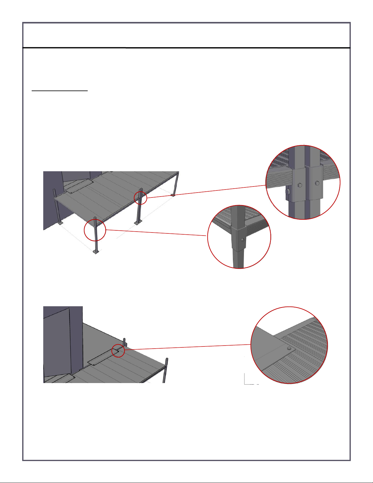
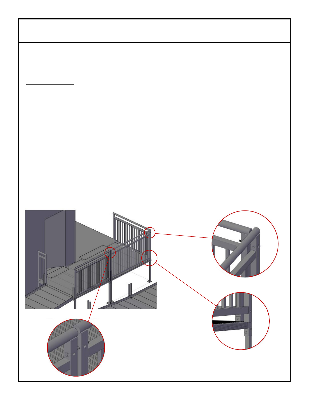
Exisng Landing/Deck/Porch to Ramp
1. Determine the ramp height required for the locaon and choose the correct support length. A ramp secon that
comes directly from an exisng landing will need (4) supports. Ensure there is 10” minimum of support tubing
extending above the support sockets. The guard rails will slide over the extended tubing.
2. Screw the .75” bolts into the support sockets located laterally on each side and both the top and boom of secon.
3. Insert supports into each socket, set at approximate 1:12 height and lightly ghten bolts. Always posion supports
where the long end of the foot pad is facing the boom (groove end) of the ramp secon.
4. Posion ramp secon in nal locaon with the “groove end” always at the boom. Make necessary slope adjustments,
level horizontally, and rmly secure .75” bolts.
5. Use a TPCOM to secure ramp secon to exisng landing in the same manner as securing a plaorm.
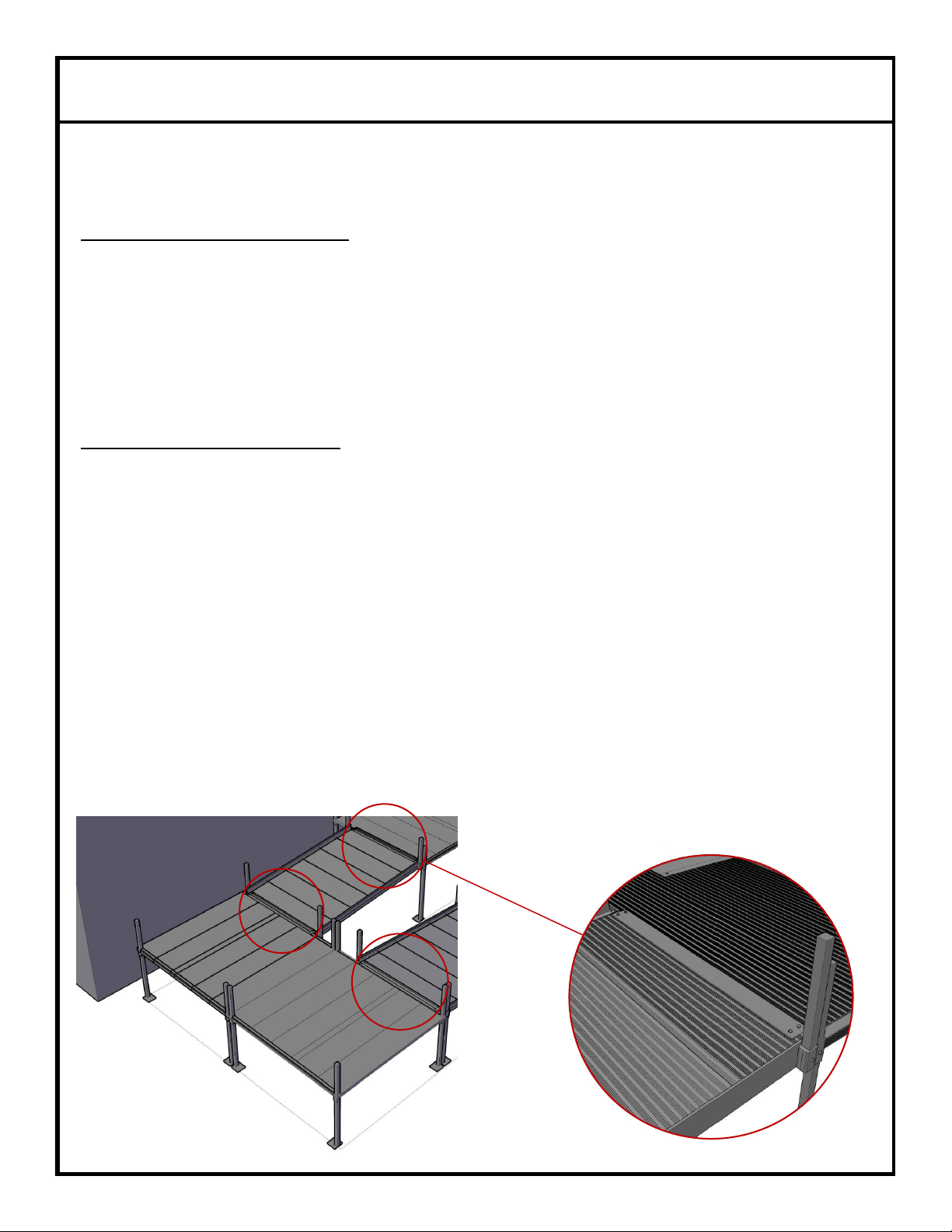
Plaorm to Ramp/Ramp to Plaorm
1. Assemble the ramp secon in the same manner as described above. If using a “tongue and groove” connecon with the
plaorm, the ramp secon will need (2) supports and (2) inserts.
2. Secure (2) supports in the boom ramp sockets (groove end) at the approximate height to meet a 1:12 slope and 14”
inserts into the top sockets (tongue end). The boom of the insert should be held ush with the boom of the ramp
socket while securing.
3. Place the “tongue” at the top of the ramp secon into the “groove” of the plaorm. The groove of the plaorm is
weight bearing and will support the weight of the top half of the ramp secon.
4. Posion top of ramp secon where the outside edge of the ramp tongue and plaorm groove are ush. The ramp
socket and corner plaorm socket should be aligned.
5. Make necessary 1:12 slope adjustments, level horizontally, and rmly secure .75” bolts.
6. Use (4) #14 x 1” Tek Screws to secure the ramp to the plaorm via BPCOM.
7. If the ramp secon is exing a plaorm on a non-groove side (standard side), the secon is considered a supporng
secon. A supporng secon will need (2) supports in the top sockets and (2) supports in the boom sockets. A BPCOM
will be used to secure the connecon between the plaorm and ramp.
8. When entering onto the standard side (non tongue and groove side) of a plaorm from a ramp secon, the ramp
“groove” should be ush with the surface of the plaorm. The boom of the ramp secon (groove end) will bu up
against the plaorm. The ramp socket and corner plaorm socket should be aligned. Use a BPCOM to secure the
plaorm to the ramp secon.

9
Ramp assembly gure page
Ramp Assembly
Ramp to Ramp/Ramp to Stop & Rest
1. Assemble ramps in the same manner as described above. Use (4) legs if the secon is a supporng secon; use (2) legs
and (2) 14” inserts if the secon is being supported by ”tongue and groove” design.
2. The lowest ramp secon will always “tongue and groove” with the upper secon of ramp.
3. Once the lower secon is connected to the upper previous secon, make necessary 1:12 slope adjustments, level
horizontally, and rmly secure .75” bolts.
4. When arriving at the last secon of ramp in the system, no supports will be used. (4) 14” inserts will be used in place of
supports. The boom of the secon will fall directly on the ground.
5. The TT48 (48” transion tread—12” deep x 1” high) will slide from the side onto the “groove” part of the boom of the
last secon of ramp. Center the TT48 with the last secon of ramp.
6. Assemble the stop & rest (level landing aer 30’ of run) like assembling a plaorm. The stop and rest will be treated like
a ramp secon in relaon to how a ramp secon “tongue and grooves”. At the top and boom.
All guard rails and hand rails will be installed aer all plaorms and ramps are assembled and set.
For quesons about what each part is and the purpose it serves, please see the plaorm and ramp
descripon page as well as the hardware package descripon page.
For proper installaon of guard rails, all ramp secon have to be set at a 1:12 slope.

10
Plaorm Guard Rails and Closures
Our standard plaorm 42” high picketed guard rail sizes: 63U (61-1/4”) Support to Stabilizer, 63S (63”) Support to Support
on any side, and 72S (72”) Support to Support only on the 6’ sides. Our standard 42” high picketed closure sizes: Support to
Stabilizer (12-11/16”) and Stabilizer to Stabilizer (11-3/16”). Consult manufacturer for 4’ x 5’, 6’ x 6’ or any custom guard
rails and closures. Plaorm guard rails will not have hand rail mounng holes. They will only have loop mounng holes.
Items needed for assembly: Proper length guard rails, proper closures, PHP, Impact wrench, 3/8” nut driver bit.
Plaorm Guard Rails
1. Determine the proper locaon for the 63U. The 63U is our universal guard rail and will t on any of the four plaorm
sides. Be mindful of the pre-drilled loop mounng holes located on the outside uprights. The loop holes will always
be on the end of the plaorm guard rail that connects to a ramp guard rail.
2. Slide one end of 63U (support to stabilizer) over one corner support unl it rest on top of the corner support socket and
allow the opposite end to rest on the surface of the plaorm. The end resng on the plaorm should be aligned with
the adjacent support. One side of the 63U will always slide over a 10” piece of support tubing that extends above the
walking surface of the plaorm and the other end will always rest on the plaorm. ***Never aempt to make a 63U
slide over two corner supports—it will not slide over them and the supports will have to be cut o in order to free up
the 63U.***
3. Mount (1) stabilizer (u-shaped piece in PHP) - solid side out—to the surface of the plaorm where the 63U end is
resng. Use a #14 x 1” Tek Screw to secure the stabilizer to the plaorm. Be careful when mounng this piece. Hold
secure while mounng to plaorm, as it can cut ngers and the hand if it starts spinning.
4. Place the end of the 63U opposite the rail over support end into the stabilizer. The 63U guard rail has been installed.
5. Determine the proper locaon for the 63S. The 63S can be installed on any side from “support to support”. Be mindful
of the pre-drilled loop mounng holes on the outside uprights. The loop holes will always be on the end of the
plaorm guard rail that connects to a ramp guard rail.
6. Slide the 63S “support over support” unl both ends rest on the top of the corner support sockets. The 63S has been
installed.
Addional screws, bolts, and nuts will be added later to secure rails in place.

11
Plaorm Guard Rails and Closures
Plaorm Closures
1. Which of the two closures is used will depend on whether the plaorm is a through plaorm, a plaorm turn, a 90°
plaorm, or a 180° turn back.
2. The 12-11/16” closure (larger closure out of the two—support to stabilizer installaon) will be used on all plaorm
opons. It always mounts to the plaorm by sliding one end over a corner support and placing the other end into a
stabilizer .
3. Slide one end of the larger closure over a corner support unl it rest on the top of the corner support socket. Let the
opposite end rest directly on the walking surface of the plaorm. The stabilizer end (end not over a corner support) of
the closure will align vercally with the ramp guard rail. The end not over the support (stabilizer end) of the larger
closure will aach to the plaorm via stabilizer.
4. Mount the (1) stabilizer on the surface of the plaorm—solid side out— and place the closure end opposite the support
into the stabilizer. For stabilizer install instrucon see #3 above. The larger closure (support to stabilizer), once
installed, should run from a corner support to a stabilizer, aligning vercally with exisng ramp guard rail.
5. The 11-3/16” closure (smaller closure—stabilizer to stabilizer) will be used on a 90° plaorm and potenally on custom
systems where needed.
6. Place the smaller (stabilizer to stabilizer) closure next to the exisng larger closure creang a 90° angle at the corner of
the plaorm where guard rails do not meet. Use this me to determine the proper locaon of the stabilizers. Remove
closure and mount (1) stabilizer to the surface of the plaorm next to the base of the exisng larger closure upright—
solid side out. Then mount (1) stabilizer to the surface of the plaorm in front of the base of the exisng ramp guard rail
upright—solid side out.
7. Place each end of the smaller closure into the stabilizers. The 90° closure installaon has now been completed.
Addional screws, bolts, and nuts will be added later to secure rails in place.
The pre-drilled holes located in middle part of the closures are hand rail bracket mounng holes.
The pre-drilled holes located only in the top poron of the closures main vercal posts will align with
the ramp guard rail holes.

12
Ramp Guard Rails
Our standard 42” high picketed ramp guard rail sizes: 2’, 3’, 4’, 5’, and 6’. We do not oer any length ramp guard rail outside
of the aforemenoned secons.
Items needed for assembly: Proper length guard rails and RHP.
1. Conrm that all ramp secons are set at a 1:12 slope before installing ramp guard rails. Ramp guard rails are welded at
a 1:12 slope to match the pre-welded slope of the ramp secons. If the ramp secons are not set at a 1:12 slope, the
guard rails will not properly slide over the supports and inserts. The guard rails will also get into a bind or will have to
much space between the ramp guard rail and plaorm guard rail, and the 5” bolts will not be long enough to secure
the two guard rails together if the ramp secons are not set at a 1:12 slope.
2. Determine the proper length guard rail based on the length of ramp secon being worked on.
3. Slide each vercal post at either end of the guard rail over the support tubing and/or insert extending 10” above the
ramp secon support sockets unl the guard rails rest directly on top of the ramp secon support socket.
4. Each secon of guard rail installed should align black cap to black and bolt hole to bolt hole with the previous guard rail.
5. Connue this procedure throughout the system unl all ramp secons have guard rails.
6. When installing the last secon of ramp guard rail, a right and le commercial loop will be installed on the inside
vercal post at the boom right and boom le part of the last secon of guard rail. Use the hand rail bracket
mounng hole to mount the commercial loop on the inside vercal post of the boom last secon of ramp guard rail.
Due to the ramp guard rails being welded at a 1:12 slope, they can only be installed one way. The
high end of the rail will always be posioned at the top of the ramp secon.
All ramp guard rails will come with pre-drilled hand rail bracket mounng holes located in the middle
poron of the rail vercal post.
Addional screws, bolts, and nuts will be added later to secure rails in place.

13
Loops, Brackets, & Hand Rails
Our commercial loops come in right handed and le handed units. The hand rail brackets come as single units and will all be
in one bag. Hand rails are available by the linear foot. Each ramp secon and closure secon will come with the proper
length to match that specic secon.
Items needed for assembly: Proper length hand rail, hand rail bracket, GBHP, 90H, RINSERT, right and le loops, LHPC,
impact wrench, 9/16” socket, 3/8” nut drive bit, #2 Phillips bit, and circular saw or reciprocang saw with metal cung
blade.
Installing Commercial Loops
Commercial loops will be installed on plaorm guard rails and the boom of the last secon of ramp guard rails.
1. Determine the proper handed unit that is to be installed and locate the bolt hole. The bolt hole for the loops will be at
the same height as the hand rail bracket bolt holes—approximately 28.5” from the base of the post.
2. Place the welded spacer located at the top inside of the loop post over the bolt hole in the guard rail. Place a 3/8” SS
washer on a 3/8” - 16—5” SS bolt and insert it into the loop post, through the spacer, through the guard rail post, unl
the threads sck out of the outside of the guard rail. Place a 3/8” SS washer over the threads and hand ghten with a
3/8” SS nut. The loop is to face outward away from the end of the ramp and is to face inward toward the middle of
the plaorm.
3. Mount a stabilizer to the ramp or plaorm guard rail at the same height as the spacer located at the boom of the loop.
The stabilizer should be facing outward where the spacer of the loop will t inside of the stabilizer. Use a #14 Tek Screw
to secure the boom loop spacer to the solid side of the stabilizer.

14
Loops, Brackets, & Hand Rails
Installing Hand Rail Brackets
1. Each ramp guard rail has one pre-drilled bracket bolt hole on the vercal post, located approximately 28.5” from the
base of the post. Plaorm guard rails will not have bracket bolt holes unless specied for a custom order. Although
the stop & rest is basically a plaorm, it will have (2) brackets mounted to the inside guard rail at each end of the
stop & rest—totaling (4) brackets.
2. Hold the hand rail bracket in place while threading a 3/8” - 16—2.5” SS bolt with washer through the bracket, through
the guard post unl the threads show on the outside of the post. Then hand ghten with washer and nut. Each ramp
secon will have (4) brackets per secon with the excepon of the boom/last secon of ramp. It will only get (2)
brackets. Remember the loops will be mounted to the last bolt holes on the boom half the last secon of ramp
guard rails.
3. Plaorm closures will also receive hand rail brackets. Turn back closures will get (1) bracket for one closure and (2)
brackets for the other closure. Through plaorm closures and turning plaorms will receive (2) brackets. 90° plaorm
closures will receive (3) brackets.
4. Repeat this procedure on each ramp secon and every closure unl all ramp guard rails and closures are equipped with
the proper amount of brackets.
Installing Hand Rails
Hand rail installaon always begins with the loops at the boom of the ramp and works up the system unl
complete.
1. Take (1) 5” aluminum insert and place (1) black O-ring in the middle. Then slide the insert into the top opening of the
loop. This loop to hand rail connecon is made only with the rst loops of the system.
2. Based o of the length of ramp secon, determine the length of handrail. Slide the hand rail over the insert that was
placed in the loop. Place other end of hand rail on top of hand rail bracket to help support while securing.
3. Place another insert with O-ring in the open end of the hand rail. Secure the handrail to the insert from the boom of
the hand rail with a Pan head Phillips Tek screw. Be sure to secure the pan head through the handrail and insert at
once. ALSO SECURE THE HAND RAIL TO THE BRACKET USING A PAN HEAD SCREW.
4. Slide the second piece of proper length hand rail over the insert and secure with pan head screw.
5. Repeat this procedure on both sides of every ramp secon. Always secure the hand rails to the brackets with a pan
head screw.
6. At the top of a ramp run the hand rail will be capped o where it meets a plaorm loop.
7. To create a 90° turn with the hand rail, use the aluminum elbow with insert at each corner. The insert will connect the
hand rail to the elbow and the elbow to the next piece of hand rail. Secure hand rail and elbow to insert with pan head
screw.
Always ensure all insert are secure and hand rails are securely fastened to

15
Final Hardware for Plaorms and Ramps and ASB’s
Items needed for assembly: Hardware that’s le from RHP & PHP, Impact wrench, 9/16” socket, 3/8” nut driver bit.
Final Plaorm Hardware
1. Slide (1) 3/8” - 16—5” SS bolt with (1) 3/8” washer through the bolt holes where the ramp guard rail end and plaorm
guard rail end meet. Secure with (1) 3/8” washer and nut. Hand ghten. A 5” bolt will always be used when connecng
guard rails end to end (Ramp guard rail to ramp guard rail / Ramp guard rail to plaorm guard rail / plarom guard
rail to ramp guard)
2. Slide (1) 3/8” - 16—4.5” SS bolt with (1) 3/8” SS washer through the bolt holes at corner of the plaorm guard rails
where 63U and the 63S meet to create a 90°. Secure the bolt in place with (1) 3/8” SS washer and nut. Hand ghten.
Always ensure the bolt threads are facing in toward the guard and not toward the outside of the plaorm.
3. Slide (1) 3/8” - 16—4.5” SS bolt with (1) 3/8” SS washer through the bolt holes where the closures meet to create a 90°,
where a closure meets a plaorm guard rail to create a 90°, and/or where a closure meets a ramp guard rail to create a
90°. Secure the bolt with washer at these aachment points with a 3/8” SS washer and nut. Hand ghten.
4. Repeat this process on every plaorm unl plaorm connecons are complete.
Final Ramp Hardware
1. Slide (1) 3/8” - 16—5” SS bolt with (1) SS washer through bolt holes from guard rail to guard rail. Secure with 3/8” SS
washer and nut. Hand ghten.
2. Repeat this process throughout the system unilaterally, unl each ramp guard rail is connected to the previous guard
rail.
Securing All Hardware
1. Start at the top of the system and use the impact wrench to secure all hand ghtened hardware. Throughout the enre
system
2. Place one hand over the bolt head and wrench down on the nut side with the impact wrench to securely
ghten the bolts to the system.
3. Conrm all ramp and plaorm .75” bolts are securely in place by using the impact wrench.
4. Use the impact wrench to secure (1) #14 Tek Screw in each support socket that has a leg support (exclude
inserts on ramp secons) The Tek Screw will be screwed into the small hole located on the outside wall of
the support sockets. Tek screw are to be used on ramp secon sockets and plaorm sockets. This will
ensure all supports are securely in place.
5. Secure (1) Tek Screw into the outside surface of every other vercal post, starng at the boom of the ramp
system. This will ensure all ramp and plaorm guard rails are securely in place.
ASB’s Installaon
1. Angle supports are used anywhere the rise of ramp or plaorm is above 30”. Aach using provided Tek
screws with angle facing the underside of the plaorm or ramp.

16
Final Steps
Recommended Anchors for securing foot pads to surface
For concrete, we recommend: hps://www.itwredhead.com/products/expansion-anchors/trubolt-
plus or comparable.
For asphalt, we recommend: hps://www.asphaltanchors.com/anchors or comparable.
Following instrucons supplied with anchors, install one anchor per foot pad.
The products listed are for reference
purpose only and do not constute
an endorsement of these products.
Final Check of Installed System
Ensure that all hardware is in place and secure
Walk on the installed system and check for any unstableness or loose rails.
Remove any debris le from installaon
**Warning**
Failure to install according to these instrucons will void the warranty and could result in serious injury .
Do not exceed load rang
In wet or icy condions, ramp may become slippery. - See winter care for removing ice and snow
Periodically check system to ensure all hardware is in place and secure. If any hardware is loose,
ghten immediately. If any piece is found damaged, do not use unl repairs are made.

17

18
Table of contents
Other American Access Lifting System manuals
Popular Lifting System manuals by other brands

Bend-Pak
Bend-Pak GP-7 Installation and operation manual

Bend-Pak
Bend-Pak HD-973P Installation and operation manual

Etac
Etac Molift Air 200 user manual

PRO LIFTS
PRO LIFTS VMB TE-076 Operating instructions & user manual

Screen Int
Screen Int SCREEN WINCH SYSTEM installation manual

Bend-Pak
Bend-Pak HDS-18EA Service manual