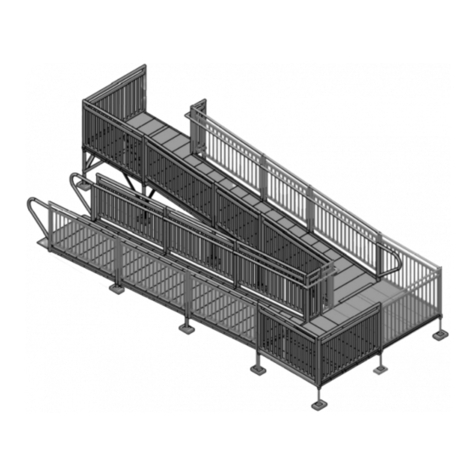
American Access XM User manual

1
Modular Ramp Installation Manual
Ver 2020-0723

2

3
CONTENTS
FOR THE AMERICAN ACCESS “XM” RAMP SYSTEM
TABLE OF CONTENTS 3
ASSEMBLY MANUAL INSTALLER AND END USER NOTES 4
IMPORTANT PROCEDURES 5a
HARDWARE CONTENT REVIEW 5b-7
HARDWARE FOR RAMPS AND PLATFORMS 8
PARTS & ACCESSORIES 9
REQUIRED AND RECOMMENDED TOOLS 10
RAMPS, PLATFORMS AND HANDRAIL SIZES DEFINED 11
PLATFORM EXAMPLES & OPTIONAL USES 12
PLATFORM RAIL DEFINITIONS - IMPORTANT 13
PLATFORM & RAMP IDENTIFIERS 14
PLATFORM CONFIGURATIONS AND PART IDENTIFIERS 15-18
PLATFORM SETUP 19
PLATFORM & RAMP CONNECTION 20
RAMP LEG ASSEMBLY 21
RAMP RUN ASSEMBLY 22
PLATFORM HANDRAIL ASSEMBLY 23
PLATFORM HANDRAIL CLOSURE KIT 24-25
TURNBACK RAILS, LOOPS AND CLOSURES 26
TURNBACK PLATFORM ASSEMBLY 27
RAMP RAIL ASSEMBLY 28
STOP-N-REST INSTALLATION & PHOTOS 29-30
LOOP ASSEMBLY 31
END TRANSITION TREAD ASSEMBLY 32
INSTALLATIONS OVER 30” 33
HURRICANE TIE DOWN INSTALLATION 34-35
FINAL CHECKS AND PERIODIC MAINTENANCE 36
WINTER CARE 37
WARRANTY REGISTRATION 38
CONTACTS AND OTHER ITEMS SOLD BY AMERICAN ACCESS 39

4
LOCAL BUILDING CODES:
It is the responsibility of the homeowner to check with local building code authorities before installing a modular
aluminum ramp.
ATTENTION INSTALLER:
• Read all instructions, including the “PERIODIC MAINTENANCE AND SAFETY”, prior to ramp assembly.
• 1,000 lb. weight capacity
• For residential use only
• Review safety features and instructions with end user and leave Assembly Manual with them
ATTENTION END USER:
• 1,000 lb. weight capacity.
• Residential use only
• Please read and become familiar with the “PERIODIC MAINTENANCE AND SAFETY” information. If you
need to obtain a new copy please contact Customer Service at 888-790-9269.
• Fill out and return the warranty information
VIEW PACKING LIST: Each ramp system is shipped with a packing list. Be sure to check that all items and tools are
present before starting installation. If you are missing the packing list, please call Customer Service at 888-790-9269 to
obtain one before beginning installation.
In addition to your ordered hardware, we have included a courtesy Hardware Care Package (HCP) with the most com-
monly used hardware parts. Some systems may end up with a small amount of “extra” hardware. This hardware may
be kept for spare parts.
ASSEMBLY MANUAL
FOR THE AMERICAN ACCESS “ XM “ SYSTEM

5
IMPORTANT PROCEDURES
FOR THE AMERICAN ACCESS SYSTEM
Please take note that your ramp system may have several different leg types and sizes, ramp sizes and even plat-
form sizes.
INSTALL NOTES:
The “XM” system uses 2 styles of leg supports.
• The ramps use a UCHANNEL style
• The platforms use a SQUARE TUBE design
MOST residential ramp systems will be 36” wide with 2’, 3’, 4’, 5’, 6’, and 8’ long ramp sections.
When a ramp is connected to or pushed against a platform, U-legs and a bridge plate must be installed
Please refer to installation manual for details.
We highly recommend that you lay out your parts until you become more comfortable and familiar with them.
Please evaluate and take notice of the components you have for the layout design you have purchased. If you
are still unclear and need assistance after your evaluation, please call customer service and we will be glad to
help.
888-790-9269 Mon-Fri 8am - 5pm Central time
Lay out all your leg supports so you can identify tallest to shortest. This will allow you to install your modular
ramp at a quicker pace.
Important Note: There may be times that you have a tall starting height, but because the first ramp or
platform begins on a porch or over a set of steps, you will be using shorter legs at that point, then once
you clear these obstacles, you will begin using the taller legs.
Your ramp system will also come with handrail loops. Loops are used when the ramp terminates on platforms or
at the end of the ramp.
Once you have laid out your components and identified them, you may begin your installation.
MAIN HARDWARE FOR THE AMERICAN ACCESS “ XM “ SYSTEM:
The hardware used on the “XM” system is 3/8” Zinc Grade 5 requiring a 9/16” socket:
• RHPN Ramp Hardware Packet
43/8” 16 - 1” Carriage Bolt for support U-Legs
83/8” 16 - 2 1/4” Carriage Bolt for Handrails
12 3/8” 16 - Flange Nut
• PHP Platform Hardware Packet
33/8” -16 - 4.5” SS Bolt
43/8” - 16 - 1/2” SS Bolt
33/8” SS nuts
63/8” SS washer
11 #14 Tek Screw
16 Black Plugs for post holes
2Rail post stabilizer (u channel)

6
CONTINUED: MAIN HARDWARE FOR THE AMERICAN ACCESS SYSTEM
• TSHP Top Support Hardware Pack - (used for extra 2 legs per ramp when required)
43/8” 16 - 1” Carriage Bolt for support U-Legs
43/8” 16 - Flange Nut
• PSCK “XM or Patriot” Series Closure Kit (Parts interchangeable with XM & Patriot Series)
1PSCKH—Patriot Series Closure Kit Hardware Pack (Parts interchangeable with XM & Patriot Se-
ries)
119” x 1” x 2” Angle for CURB USE
1Handrail Loop
1Bridge Plate
• PSCKH “XM or Patriot” Series Closure Kit Hardware * (Parts interchangeable with XM & Patriot Series)
21 1/2” handrail tube pivot swivel connectors (grey plastic) *
21.34” x 5” aluminum tube inserts with rubber “O” ring
7#14 x 1” Tek Screw SS Hex Head—secure pivot and SCH to rail
12 #8 x 3/4” Tek Screw Pan Head Philips
* Note: pivot swivels require a 5/32 allen wrench to tighten them.
• RSK Ramp Starter Kit
1TT36 - Transition Tread 36” x 12” for entrance to ramp system
1TP - Transition Plate 9.25” x 32” for transition from ramp to deck, porch, etc..
2PSLOOP - End Handrail Loops
1RSKH - Ramp Starter Kit Hardware Pack
1CAPHP - (8) 1 1/2” Black Round Plastic End Cap for 1.5” handrails
• RSKH Ramp Starter Kit Hardware
8#8 x 3/4” Tek Screw Pan Head Philips
4#14 x 1” Tek Screw SS Hex Head
41.34” x 5” round aluminum rail insert (loop attachment use)
1CAPHP (8 pack of 1 1/2” round black caps for rails as needed)

7
Hardware Package content review
MAIN HARDWARE USED AS FOLLOWS:
The hardware used on the “XM” Ramp system is 3/8” Zinc Grade 5 requiring a 9/16” socket, 3/8” driver head
and a philips head screwdriver:
• SCH Sleeve Connector Hardware
41.34” x 5” aluminum tube inserts with rubber “O” ring
• HCPP Hardware Care Package Patriot (spare parts) - also used for XM series
15/32 Short Arm Hex Allen Wrench
23/8” - 16 x 2 1/4” Carriage Bolt for ramp rails
23/8” - 16 x 1” Carriage bolt for U-Legs
11/4” - 20 nylon insert - connecting pivot swivel halves
11/4” - 20 x 1” button cap screw - connecting pivot swivel halves
43/8 - 16 Flange Nut
21 1/2” Black Round Plastic End Cap for 1.5” handrails
13/8” - 16 - 4.5” SS bolt, platform handrail use
13/8” - 16 - 1/2” SS bolt, platform leg socket use
13/8” - SS nut
23/8” - SS washer
6#14 x 1” Tek Screw
ALL hardware should be tightened at a torque rate of 40 . lbs for final assembly.
Pushing or pulling the handle of a wrench connected to a nut or bolt produces a torque (turning force) that loos-
ens or tightens the nut or bolt. If using a 12 volt Hitachi impact wrench (Hitachi WH12DMR) it will produce 90 ft lbs of
torque.
FOR THE AMERICAN ACCESS SYSTEM

8
Included Ramp Hardware
* = Optional hardware depending on ramp layout
* 1/4” x 1” cap screw #8 x 3/4” TEK screw * #14 x 1” TEK screw
Use to install U-Leg
3/8” -16 x 1” carriage bolt
Use to Install Handrails
3/8” -16 x 2 1/4” carriage bolt
3/8” Flange Nut
* 1/4” Nylon Insert * 5/32” short arm Hex Allen Wrench
Included Platform Hardware
Use to cross-bolt two Handrails
3/8” - 16 - 4.5” SS bolt 3/8” - 16 - 1/2” SS bolt 3/8” - 16 - SS nut 3/8” - SS flat washer * #14 x 1” TEK screw
5/8” plastic plug Aluminum rail stabilizer

9
Parts and Accessories
Slotted “F” Stringer
TP - Transition Plate 9.5”x34”
TPL - Transition Plate Large 12”x34”
TT36 - Transition Tread
1’ x36”
ULEG (varying sizes)
BP - Bridge Plate 3” x 32” PSCK
For Patriot or XM Series
Closure Kit
PSK (2 per)
Handrail Sleeve Connector
1.34” x 5” aluminum tube inserts with rubber “O” ring Black Handrail Cap
Platform Handrails Ramp Handrails
Loop ASB
Angle Support
bracket
Platform Leg - (varying sizes)
Install Note:
• Platform Angle is 1.5” x 1.5”
• Ramp Angle is 1” x 2” with holes on
each end

10
Required Tools
Cordless Drill
Ex. Dewalt Cordless Drill
Ratchet and 9/16” &
1/2”socket
Philips driver to fit TEK screws
30’ or larger tape measure Rubber Mallet 4’ Level
Optional Impact Wrench for faster
install time
2” tube cutter for aluminum 50’ string and line level or
laser level
Ex. Hitachi impact wrench
25 lb sand for leveling pavers Small Spade for aid in ground
work to level pavers as needed Portable Sawzall

11
Platforms, Ramps and Handrails
Universal—Straight runs or 90 degree turns
Universal—Straight runs or 90° turns
90° turns, 180° turns using (2), 4’ straight through
or 5’ straight through.
90° turns, 180° turns using (2), 5’ straight through
or 6’ straight through.
RAMPS
36” wide—2’, 3’, 4’, 5’, 6’, and 8’
48” wide—2’, 3’, 4’, 5’ and 6’
Standard 2 line handrail
34” tall residenal 4” on center picket rail
RAMPS
5’ X 6’
5’ X 5’
4’ X 5’
4’ X 4’
Picket Rail Loop
XM & Patriot Ramp Loop

12
Platforms Examples and Optional Uses
One (1) closure kit is included with the purchase of each platform.
Additional closure kits can be purchased separately.
ORDERING NOTE: Be specic
when ordering plaorms to insure
proper rails are shipped for your
desired use.

13
Platform Rail Definitions - IMPORTANT
INSTALL NOTE: YOUR PLATFORM RAILS ARE DIFFERENT THAN YOUR RAMP RAILS
The Platform rails on the “XM” system are installed by sliding the proper length rail OVER the exposed leg on the cor-
ners of the platform.
As noted in the platform drawings on pages 15-18, there are 4 sizes of platform rails.
First let’s define “Closed” and “Open” sides of the platform.
Female groove end
Male lip end
Closed side Closed side
(Example of a Set Rail on a 5x5 plaorm)
SET RAIL - rail goes plaorm leg over
plaorm leg on the closed side of the
plaorm.
Top rail is 63” long
(Example of a Universal Rail on a 5x5 turn plaorm)
UNIVERSAL RAIL - 1 side of rail goes over a
plaorm leg and the other side, tech screw into a rail
stabilizer (U-shaped) and bus against the other rail or
closure kit
Top rail is 61.25” long
Female groove end
Male lip end
The “OPEN” side is either where the Female groove or Male lip are
showing.
The “CLOSED” side is capped off with an aluminum C channel to cover
the open end of the treads.
Plaorm Leg
Goes up through welded
socket on the plaorm
SET RAIL
63”
UNIVERSAL RAIL
61.25”
U-stabilizer

14
Platforms are designed to connect to one another to make different sizes
for different applications.
We offer 4 different platform sizes;
• 51” x 51” platform (4’ x 4’)
• 63” x 51” platform (5’ x 4’)
• 63” x 63” platform (5’ x 5’)
• 72” x 63” platform (6’ x 5’)
By combining the different sizes you can create a platform that will best fit
your need.
(Example of Universal Rail on a straight through plaorm)
UNIVERSAL RAIL - goes over 1 plaorm leg and bus against the
other rail or closure kit tech screwed into the rail stabilizer.
Top rail is 61.25” long
Shown here the UNIVERSAL RAIL bus up on the closed side with a
Closure Kit in the corner.
Bridge plate
U-Leg
Plaorm Leg
Loop
Ramp Handrail
Closure Kit
U-stabilizer
Curb

15
63” X 63” Straight Landing
LSP6363
• LSR63S (1)
• LSR63U (1)
• PSCK (1)
• STBLZR (1)
MALE END
FEMALE END
FEMALE END
MALE END
63” X 63” Turn Landing
(requires extra PSCK purchased)
LSP6363
• LSR63S (1)
• LSR63U (1)
• PSCK (2)
• STBLZR (2)
5 X 5 Platform Rails: (Turning Surface 60” - Outside socket to socket is 63”)
SET RAIL Leg over Leg rail on the CLOSED side of the platform - the top rail measures 63”
UNIVERSAL RAIL Over 1 leg used on the OPEN side or Closed side - the top rail measures 61.25”
Used to butt up against the SET rail in a 90 degree turn layout
OR butts up to the Closure Kit Post in a straight run
NOTE* When installing a 90 degree turn and continuing a ramp run, you must purchase an additional closure kit
Closed Side
Closed Side
Closed Side
Closed Side
No tongue-n-
groove this side or
opposite side

16
4 X 5 Platform Rails:
SET RAIL Leg over Leg rail on the CLOSED side of the platform - the top rail measures 51”
UNIVERSAL RAIL Over 1 leg used on the OPEN side or Closed side - the top rail measures 61.25”
Used to butt up against the SET rail in a 90 degree turn layout
Special Ordering of rails are required if you are using a 4x5 platform as a straight run
4’ deep straight uses two (2) 51” rails / 5’ deep straight run uses two (2) 63” rails
INSTALL NOTE: When installing a 90 degree turn and continuing a ramp run, you must purchase an additional closure kit
63” x 51” Turn Landing
(requires extra PSCK purchased)
LSP6351
• LSR51S (1)
• LSR63U (1)
• PSCK (2)
• STBLZR (2)
FEMALE END
MALE END
63” x 51” Straight Landing
LSP6351
• LSR51S (2)
• PSCK (1)
• STBLZR (1)
FEMALE END
MALE END
63” x 51” Straight Landing
LSP6351
• LSR63S (2)
• PSCK (1)
• STBLZR (1)
FEMALE END
MALE END
Closed Side
Closed Side
Closed Side
Closed Side
Closed Side

17
FEMALE END
MALE END
5 x 8 90° turn landing
LSP6351 (2)
• LSR51S (3)
• LSR63U (1)
• PSCK (1)
• STBLZR (1)
4 X 5 Platform Rails: Optional uses as a turnback or a long 90 degree turn
SET RAIL Leg over Leg rail on the CLOSED side of the platform - the top rail measures 51”
UNIVERSAL RAIL Over 1 leg used on the OPEN side or Closed side - the top rail measures 61.25”
Used to butt up against the SET rail in a 90 degree turn layout
Special Ordering of rails are required if you are using a 4x5 platform as a straight run
4’ deep straight uses two (2) 51” rails / 5’ deep straight run uses two (2) 63” rails
INSTALL NOTE: When installing a 90 degree turn and continuing a ramp run, you must purchase an additional closure kit
FEMALE END
MALE END
5 x 8 turnback
LSP6351 (2)
• LSR51S (2)
• LSR63U (2)
• PSCK (2)
• STBLZR (2)
Closed Side
Closed Side
Closed Side
Closed Side

18
4 X 4 Platform Rails:
SET RAIL Leg over Leg rail on the CLOSED side of the platform - the top rail measures 51”
UNIVERSAL RAIL Over 1 leg used on the OPEN side or Closed side - the top rail measures 49.25”
Used to butt up against the SET rail in a 90 degree turn layout
OR butts up to the Closure Kit Post in a straight run
Special Ordering of rails are required if you are using a 4x5 platform as a straight run
4’ deep straight uses two (2) 51” rails / 5’ deep straight run uses two (2) 63” rails
INSTALL NOTE: When installing a 90 degree turn and continuing a ramp run, you must purchase an
additional closure kit
51” x 51” Straight Landing
MP44U
• LSR51S (1)
• LSR51U (1)
• PSCK (1)
• STBLZR (1)
FEMALE END
MALE END
51” x 51” Turn Landing
(requires extra PSCK purchased)
MP44U
• LSR51S (1)
• LSR51U (1)
• PSCK (2)
• STBLZR (2)
FEMALE END
MALE END
Closed Side
Closed Side

19
Platform Setup
NOTE: YOUR PLATFORM LEGS ARE SQUARE TUBES, THIS IS DIFFERENT FROM THE RAMP U-LEGS
* Set out your platform with the FEMALE GROOVE facing in the direction of the first downward ramp run.
* Locate the Platform Hardware Pack (PHP). This is your hardware required to install the leg supports and handrails.
* Open the hardware pack and remove the 4 - 3/8” x 1/2” bolts. Insert the bolts into each leg socket on the platform
making sure to leave room in the leg socket for the leg tube to freely slide into the socket.
* Determine your platform height and find the tubular legs that are approximately 10” or greater than your overall height.
Example: The rise is 28”, so the platform needs to be set at 28" from the ground to the top surface of the
platform. The appropriate leg size for this configuration would be the 40" legs (28"+10"=38").
Platform legs are available 20",30",40", 50” and continuing increments of 10". The platform rails will be installed
over the legs. This is why 10” over the platform surface is ideal for your leg height.
* Next determine the BEST position for your legs. Note that the foot pad is “off set” allowing you to tuck the pad under-
neath the platform when installing.
* Slide the tubular leg into the socket from the bottom side of the platform. Measure from the surface of the platform
down to the bottom of the footpad. Set it at your desired height by slightly tightening the bolt to hold the leg in
place. DO NOT OVER TIGHTEN. Adjust height when using patio blocks under the legs. See note below.
* Install Note: A minimum of 10” or more of the platform leg should be showing above the platform
INSTALL NOTE: When installing legs on grass or uneven surfaces, a 12” x 12” patio paver is required to be set under
the aluminum leg to prevent the leg from sinking into the soft ground over longer periods of time. Level out the patio
paver to acquire level contact between the patio paver and the aluminum footpad. We recommend sand under the patio
paver to help in leveling it out.
After all 4 legs have been installed,
• Set your platform and make level adjustments using a 4’ or 6’ bubble level for accuracy.
• Once level, proceed to tighten your leg socket hardware.
12” x 12” pao paver
Noce how foot pad is
turned so that it is tucked
under the plaorm

20
Platform and Ramp Connection
* Once your Platform is set, you are ready to connect your first ramp section to the platform.
* Determine the length of the first ramp section you are going to install. You will need to locate the ramp leg supports
which are the U shaped slotted tubes as shown on page 9.
* To determine your leg length, deduct the length of the ramp section from the starting height of your platform.
Example: Your starting height was 28” and your first ramp section is an 8’ ramp, (28 - 8 = 20). The smallest
legs for ramps begin at 16” and increase in increments of 10”. The leg best used for a 20” rise is a 26” leg.
Refer to page 21 for installation of leg
* After your legs are installed you can set your first ramp section in place by placing the “MALE” lip of the ramp sec-
tion into the “FEMALE” groove of the platform. Push your ramp to the out most edge leaving a space of approximate-
ly 3” from the edge. This will allow hand clearance between the ramp rail loop and the platform rail when you add
handrails.
Platform with Female Groove
Ramp with MALE lip
INSTALL NOTE: ** Slide ramp section 3” in
from the edge
INSTALL REQUIREMENT: Ramps coming OFF platforms
should ALWAYS have a leg as support even though the
ramp sets in the platform groove.
INSTALL REQUIREMENT:
Bridge Plate—(3”X32”)
Must be installed over every ramp to plaorm
connecon
Table of contents
Other American Access Lifting System manuals
Popular Lifting System manuals by other brands

Bend-Pak
Bend-Pak GP-7 Installation and operation manual

Bend-Pak
Bend-Pak HD-973P Installation and operation manual

Etac
Etac Molift Air 200 user manual

PRO LIFTS
PRO LIFTS VMB TE-076 Operating instructions & user manual

Screen Int
Screen Int SCREEN WINCH SYSTEM installation manual

Bend-Pak
Bend-Pak HDS-18EA Service manual