American Changer AC107 Setup guide

©2018 American Changer
Manual Ticket Dispenser 022018
American Changer
Ticket
Dispenser Series
Installation, Operation,
and Service Manual
Changing the Industry℠
Installers & Service Technicians
Read and understand the instructions
detailed in this manual.
Owners & Operators
Keep this manual in a safe place to
provide to any service technicians
working on this machine.
American Changer
1400 N.W. 65th Place, Ft. Lauderdale, FL 33309
Tel (954) 917-3009 • Fax (954) 917-3079
www.americanchanger.com www.hoffmanmint.com
Models: AC107, AC110,
AC111, AC115, and AC125

2

1
Table of Contents
Section 1 –Product Overview
1.1 –Machine Specifications……………………………………………………………………………………………………………..
2
1.2 –Warranty Information……………………………………………………………………………………………………………….
2
1.3 –Machine Safety…………………………………………………………………………………………………………………………
3
Section 2 –Setup & Installation
2.1 –Setup…………………………………………………………………………………………………………………………………………
5
2.2 –Mounting Instructions……………………………………………………………………………………………………………….
6
Section 3 –Operational Overview
3.1 –Component Description…………………………………………………………………………………………………………..
8
3.2 –Functional Description (AC107 & AC110)…………………………………………………………………………………..
13
3.3 –Out-of-Service Conditions & Error Codes (AC107 & AC110)………………………………………………………
13
3.4 –Programming Menu (AC107 & AC110)………………………………………………………………………………………
15
3.5 –Remote Loading Software to the Flex-2 Board (AC107 & AC110)……………………………………………..
19
3.6 –Functional Description (AC111, AC115, & AC125)……………………………………………………………………..
20
3.7 –Out-of-Service Conditions & Error Codes (AC111, AC115, & AC125)………………………………………….
20
3.8 –Programming Menu (AC111, AC115, & AC125)
21
Section 4 –Maintenance
4.1 –Ticket Dispenser Maintenance.………………………………………………………………………………………………..
25
4.2 –Banknote Validator Maintenance………………………………………………………………………………………………
26
4.3 –Coin Hopper Maintenance………………………………………………………………………………………………………..
30
4.4 –Warranty Terms and Conditions………………………………………………………………………………………………..
31
©2018 American Changer
All rights reserved. No part of this work covered by
copyrights herein may be reproduced or copied in any
form or by means –graphic, electronic or mechanical,
including photocopying, recording, taping or information
storage and retrieval systems –without the written
permission of American Changer

2
Section 1 –Product Overview
1.1 –Machine Specifications
Operating Voltage (selectable by switch on power
supply)
Set at 115VAC: 90 ~ 132VAC 4.0A
Set at 230VAC: 180 ~ 264VAC 6.0A
Power Consumption
100W Max
Operating Temperature
41°F to 104°F / 5°C to 40°C
Interface to Ticket Dispenser
24VDC, 2.5 amps max
*Note: Specifications stated herein may vary without notice. Capacities are approximations and may
vary.
1.2 –Warranty Information
PLEASE REFERENCE SECTION 4.4 ON PAGES 31 AND 32 FOR AMERICAN CHANGER’S DETAILED LIMITED
WARRANTY AND EXCLUSIVE REMEDIES. SOME HIGHLIGHTS FROM SAID SECTION ARE:
Ticket Dispenser(s), Displays, and Logic Board(s)
These items are warranted for one year from date of purchase.
Banknote Validator
This item is warranted for two years from the date of purchase.
COVERED
Manufacturers’ defects in workmanship or materials
NOT COVERED
Damage caused by shipping or physical abuse
Misapplication
Vandalism
End users’ attempt, on their own, to repair components
Cleaning and maintenance
Power surges and lightning strikes
A Return Material Authorization number (RMA #) must be obtained from American Changer
Corporation before returning a unit for repair; warranty or otherwise. A copy of invoices must
accompany any and all warranty work.

3
Section 1.3 –Machine Safety
Your safety and the safety of others are very important to
American Changer.
We have provided important safety messages in this manual and on your machine. Always read and
obey all safety messages.
All safety messages will tell you what the potential hazard is, tell you how reduce the risk of injury, and
tell you what can happen if the instructions are not followed.
This is a safety alert symbol.
This symbol alerts you to potential hazards that can kill or hurt you and others.
All safety messages will follow the safety alert symbol and either “DANGER”,
“WARNING”, or “CAUTION”.
These words mean:
You can be killed or seriously injured if you don’t immediately
follow instructions
You can be killed or seriously injured if you don’t follow
instructions
You can be injured if you don’t follow instructions
Distributors, retailers, operators, and/or service people are to insure the following warning label is
properly affixed on the ACC products to which you/they are using and/or servicing in order to help
meet the applicable Proposition 65 requirements. For more information go to
www.P65Warnings.ca.gov

4
Important Safety Instructions
DANGER: To reduce the risks of severe injury
secure the machine to a stable structure.
WARNING: To reduce the risk of electrical shock,
disconnect all electrical power to the machine
before servicing.
NOTICE: For indoor use only.
NOTICE: Ensure this machine is level when
installed
SAVE THESE INSTRUCTIONS
American Changer does not guarantee machines (products) or services to be 100% secure against criminal
attempts. All machines (products) and services are to be used in accordance with business best practices and the
owner’s or operator’s best judgement.
Installation, use, service and maintenance must be performed in accordance with applicable machine (product)
manuals provided by American Changer and comply with any and all pertinent laws or regulations.
Inspect your machine (product), at a minimum annually, by a qualified service technician.
Dimensions and weights are reasonably close estimates. Specifications in this manual can vary without notice.

5
Section 2 –Setup & Installation
2.1 –Setup
NOTICE: THIS MODEL MACHINE IS FOR INDOOR USE ONLY.
Inspect for any connectors or components that may have been dislodged during shipping. The lock and keys for
your changer will be inside the manila envelope along with this manual and other pertinent information. To install
the lock, insert the cylinder into the hole in the middle of the T-handle and push until it stops. Turn the key until
you hear it “snap." Turn the key counterclockwise ¼ turn and remove the keys.
NOTE: The only way to get a duplicate set of keys made is to save the tag that comes with the keys. The ID #
begins with “AC” or “ACC” followed by digits.” If you purchased Medeco locks with your machine the ID will
begin with “7RA” followed by digits.”
CHECKING SHIPMENT: Be sure to check the shipment against the Bill of Lading for shortages. Also, check for
external damage to the packaging. Note any shortages and/or damage to the packaging on the Bill of Lading in
the presence of the carrier and ask the carrier to initial on the Bill of Lading accordingly. Immediately report any
shortages or damage to the packaging to the carrier and American Changer.
TEST: Before permanently installing the changer, do a functional test to verify that there is no shipping damage to
your new changer.
Plug the power cord into a dedicated, grounded 120VAC outlet. The machine is preset to accept $1, $5, $10 and
$20 banknotes and dispense tickets (unless otherwise specified at the time of purchase).
Fill each of the card dispensers with a minimum of 1 card. On the Main Logic Board, turn the switch on the bottom
right corner “ON.” The rocker switch has an “I” and “O” printed on it. When the “I” is pressed down, the changer is
“ON.”
If the machine does not function properly please contact American Changer’s Technical Support Department at
service@americanchanger.com or 1-888-741-9840.

6
2.2 –Mounting Instructions
This machine must be installed in accordance with local codes. If you are unsure in any way what your
local codes are or unsure of anything in the following steps, please hire a licensed professional to
mount your machine.
1. Disconnect any and all AC power going to the machine. (Unplug AC line cord from the rear of the
machine.)
2. Note: You will need to verify with the building code enforcement to see if it is allowable to plug the
changer into a grounded outlet. If it is not, there must be 120VAC run through conduit or other
means to meet local codes to the changer. If it is not required, proceed to step #6.
3. Have a licensed electrician run the conduit, install the new breaker, wire and help decide how the
wiring will enter the changer (from the back or the bottom).
4. After the conduit has been installed, proceed with securing the machine to a stable structure.
5. Find an appropriate stable structure which to secure the machine to.
6. NOTICE: BEFORE SECURING ENSURE THE MACHINE IS LEVEL.

7
7. : PROPERLY SECURE MACHINE (PRODUCT) TO THE FLOOR SO THE MACHINE
(PRODUCT) CANNOT BE MOVED OR TIPPED. USE STRUCTURAL SOUND FASTENERS THAT CAN BE
PROPERLY TIGHTENED AND SECURE THE MACHINE (PRODUCT) THROUGH EACH OF THE HOLES IN
THE BASE OF THE MACHINE (PRODUCT) TO THE APPLICABLE SURFACE TO WHICH IT IS BEING
SECURED.
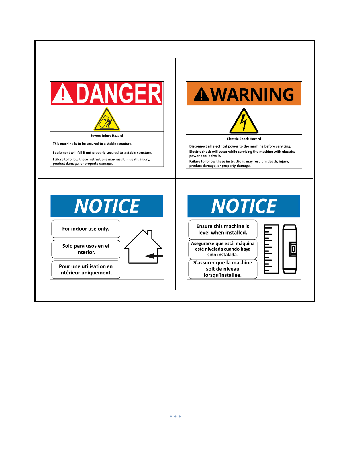
8. Use the four holes located in the bottom of the cabinet to secure the machine to a stable structure.
9. Verify that the machine is properly secured to the stable structure.
10. Connect your AC line to the rear of the changer. Then plug it into the outlet.
a. Do not use an extension cord unless allowed by the building electrical code.
b. Installation is completed. Proceed to the “Programming the Changer” section.
The proper performance of your American Changer machine is directly related to the quality of the power it is
supplied. AC power fluctuations, including blackouts, brownouts, over voltages, sags, surges, and spikes may cause
the machine to miss pay. To ensure the most trouble-free operation, we strongly recommend plugging all of our
machines into a DEDICATED AC outlet (this means there are no other machines on location plugged into the same
AC line). A simple way to check if this is true is to turn off the breaker associated with our machine at the breaker
box. No other equipment on location should lose power.
Additionally, if your unit is located in an area prone to lightning storms or other sources of frequent power
disturbances, we also strongly recommend using an Uninterruptible Power Supply (UPS). If power is lost during a
payout to a customer, a UPS will allow your machines to complete the transaction that would otherwise not be
completed. In some cases, a UPS may also correct long-term under and/or over voltages on the AC line by
converting to the proper line voltage before the power reaches the machine.
Every American Changer machine has a surge suppressor built into the main logic board. This helps eliminate
power related noise problems, but it will not protect from substantial voltage spikes or nearby lightning strikes. If
this is a concern for your area, we recommend purchasing a commercial grade UPS with integrated surge
protection. NOTE: A POWER STRIP IS NOT A SURGE PROTECTOR.

8
Section 3 –Operational Overview
3.1 –Component Description
Card Dispenser
The ticket dispenser is a pulse device that interfaces through the use of a proprietary adaptor board. The
AC107 and AC110 use the Benchmark Intelli-Triple ticket dispenser. All other ticket dispensing model
machines use the Deltronic Labs Inc. DL 1275 ticket dispenser.
BenchMark Intelli-Triple
Deltronic Labs Inc. DL 1275
Loading the tickets into the Intelli-Triple ticket dispenser
Place the tickets in the ticket channel,
positioning them on top of the ratchet and
close the top slide. Be sure the top slide has
magnetically set back into position.
Now press the button under the dispenser
corresponding to the side you just loaded.
The Intelli-Triple will automatically position
the tickets in the proper place.
Repeat the task on the other side and you are
ready to go. If the machine runs out of tickets
or a jam occurs, correct the problem and press
the corresponding button to set the dispenser
for operation.

9
Loading the tickets into the DL 1275 ticket dispenser
Note: It is not necessary to detach the ticket
dispenser from the door (AC111) or cabinet
(AC115/125) in order to load tickets.
1. If there are tickets remaining in the dispenser,
remove them before proceeding, and empty the
ticket bin. Loosen the grip of the embossing rollers
by pressing the metal plate and metal spacer
toward each other, using your thumb and
forefinger (apply pressure at the points indicated
by the two large arrows in the figure to the right).
While the rollers are being held apart, use your
other hand to pull the tickets out of the
mechanism.
2. Refill the ticket bin with a fresh box/pack of fan
fold tickets.
3. Pull the top row of tickets up, directing them
around the ticket router, as seen in the picture to
the right, and feed them face-up into the entrance
of the ticket dispenser mechanism, between the
top and bottom metal ticket guides. If necessary,
gently push the locating spring out of the way with
one hand while feeding the tickets with the other.
4. Making sure the tickets pass through the
channel in the optical sensor, continue to push
them in until the front ticket presses against the
embossing rollers.
5. Locate the UP button on the Main Logic Board
(see figure2). Press and hold the UP button for
approximately 3 seconds until the ticket
dispenser’s motor begins to run, and then release
the button; this initiates the ticket Auto-Feed
feature on the Main Logic Board. During the Auto-
Feed procedure, the tickets are pulled through the
dispenser’s ticket path, and automatically fed to
their appropriate “standby” position, which is flush
with the front of the machine.
Note: One or more tickets may be fed
through the slot during the Auto-Feed operation;
these maybe torn off and discarded.
Ticket Router
Optical
Sensor
Top Ticket
Guide
Locating
Spring

10
Coin Hopper –Only available in the AC107 and AC110
The hopper uses the ccTalk communication protocol. It can dispense coins or tokens ranging in size from
21mm to 30mm in diameter and 1.25mm to 3.30mm in thickness. An option is available to dispense
smaller coins.
I/O Board and External LCD Display –Used in the AC107 and AC110
The I/O board allows the main board to interface with the LCD display and displays the packages to the
customer. The LCD display is located behind the I/O board pictured below.
Flex I/O to Flex-2
Main Logic Board
Harness
Flex I/O to
Internal 12 Key
Keypad
Flex I/O to 4
Arrow Selection
Overlay
Put coins into this opening
Coin Counting Optic
Motor
12-Pin female connector
(located in rear of hopper)

11
Flex-2 Main Logic Board –Used in the AC107 and AC110
Hopper Adaptor Board –Used in the AC107 and AC110
The machine uses a “Hopper Adaptor Board” to control the ticket dispenser. It uses ccTalk protocol.
I/O Board
24VDC Power
Input
Select Switch for
accessing the
programming
menu
SD Card
On/Off
Switch
Hopper
Adaptor Board
Coin Hopper
Printer
Bill
Validator
Nayax
Credit Card
System
Magtek
Credit Card
Reader
Ticket
Dispenser
Harness
Adaptor Board to
Flex-2 Main Logic
Board

12
12 Key Keypad –Used in the AC107 and AC110
The machine uses a 12 key keypad for entering information into the programming menu. It is located
inside of the machine.
Universal Main Logic Board –Used in the AC111, AC115, and AC125
24VDC Power
Input
Up, Down, and Select Buttons.
Used for accessing and
navigating the programming
menu
On/Off
Switch
Ticket Dispenser
Out of
Service
Light
Bill
Validator

13
Bill Validator –Used in all models
This model machine may have been sold without a bill validator. It is intended to operate using a 24VDC
bill validator using the MDB protocol.
6-Pin (MDB) Connector Pinout:
Pin #1 - +24VDC Power
Pin #2 - DC Power return
Pin #3 - Not Used
Pin #4 - Master Receive
Pin #5 - Master Transmit
Pin #6 - Communications Common
3.2 –Functional Description for the AC107 and AC110
1. Dispense
This machine dispenses tickets and coins as change.
2. Payment
The machine accepts payment in the form of cash or credit.
3.3 –Out-of-Service Conditions & Error Codes for the AC107 and
AC110
System
Failures
Below are conditions that will cause the machine to go into an
“Out-of-Service” mode. The message “Temporarily out of
Service” will be displayed on the external LCD display when
the machine is in an “Out-of-Service” mode.
Note: These error messages can only be viewed by
accessing the “Programming Menu”.
Ticket
Dispenser
Ticket Dispenser Error Conditions
Low
Ticket Dispenser is empty.
No Comm.
The Flex-2 main logic board is unable to communicate with
the card dispenser’s Hopper Adaptor Board.
Coin
Hopper
Coin Hopper Error Conditions
Opto’s
Indicates the coin counting optic is blocked. The exit path may
be obstructed, or the Optic Board may be bad.
6-Pin (MDB)
4
1
6
3

14
No Comm.
The Flex-2 main logic board is unable to communicate with
the coin hopper. The hopper may be disconnected, have a
damaged harness, or may need to be repaired or replaced.
High
Current
The hopper motor exceeded its maximum threshold for
current. Inspect for a jammed coin preventing the coin belt
from moving, or a stalled or shorted motor. Repair or replace
the hopper.
Low
The amount of coins in the coin hopper is below its
operational threshold. First ensure there are enough coins in
the coin hopper to completely covert the metal plates located
at the bottom of the hopper. Second use Scotch-Brite to
scrub the metal plates. This is effective on dull plates. Repair
or replace the hopper.
Timed Out
The coin hopper did not complete a payout in its allotted time
frame. Check the hopper for any coin jams or mechanical
obstructions preventing coins from exiting. Have the unit
repaired or replaced.
Bill
Validator
Bill Validator Error Conditions. If the validator fails, the display
shows a “Credit Cards only” message if applicable.
Motor
Validator stacker/transport motor has failed. Repair or
replace the bill validator.
Sensor
Sensor failure. Check for dirty sensors. Repair or replace the
validator.
CheckSum
Indicates error with the firmware file stored on validator main
board. Repair or replace the bill validator.
Jammed
A bill or debris is jammed in the validator bill path. Check bill
path for a jammed bill or debris. Repair or replace the bill
validator.
Cashbox
The cashbox is not installed on the bill validator. Ensure the
bill box is properly installed on the bill validator. Repair or
replace the bill validator.
No Comm
The Flex-2 main logic board is unable to communicate with
the bill validator.
Can’t
Enable
System has tried to enable the validator several times without
success.

15
Credit
Card
Credit Card System error conditions. If the credit card
processing fails, the display shows a “Cash only” message.
No Comm
The Flex-2 main logic board is unable to communicate with
the credit card system.
No Reader
Reader is not connected or defective. (Only if using DataCap
IPTranLT with Magtek Reader)
Coin
Acceptor
Coin Acceptor Error Conditions
Credit Sns.
Credit sensor blockage or failure
Piezo Sns.
Piezo sensor blockage or failure
Exit Sns.
Exit sensor blockage or failure
Reject Sns.
Reject sensor blockage or failure
Return
Mech
Unit failure. Needs to be replaced.
Thermistor
Thermistor failure
No Comm
The Flex-2 main logic board is unable to communicate with
the coin acceptor.
3.4 –Programming Menu for the AC107 and AC110
To enter the programming menu, begin by pressing the “Select Switch” on the Flex-2 main logic board.
Pressing the select switch will bring the display to show “Enter Access Code.”
Use the Flex Programmer Board to enter the access code. The default code from the factory is “1234”
To exit the programming menu or the “Enter Access Code” screens press the “Select Switch”
Use the Flex Programmer Board to navigate the menus. Press the “Cancel” button and enter a menu
number to be brought immediately to that menu or press the Back/Next button to step through the
menus.
All the menus work the same:
No/Yes: Selects status
Back/Next: Selects the item
Exit: Exits the setup menu

16
Menu 01 –Print Help Menu
A list of the menus and their corresponding numbers is printed by the external printer.
Menu 02 –System Info
The payout information and configuration settings are printed by the external printer. Aside from those,
the following information is also included in the System Info printout:
Software Revision
Valid1 Status
Valid2 Status
Ticket Dispenser #1 Status
Hopper #1 Status
Hopper #2 Status
Hopper #3 Status
Credit Status
Printer Status
Coin Acceptor Status
Temperature Info
FTPServer Info
Menu 03 –Button Price
Define the amount charged for each selection (1-3). Selection 4 is used to purchase individual tickets.
Menu 04 –Button Payout
Sets up payout count for the 3 selection buttons.
Menu 05 –Enable Bill
This system only uses MDB validators. Depending on what type of MDB validator is used, the display will
only toggle between the denominations accepted by the bill validator.
Menu 06 –Payout Table
Only bills enabled in Menu 05 will be available in this menu. Enter the # of items dispensed for each bill
denomination.
Menu 07 –Enable Hoppers and Ticket Dispenser
Enable or disable the ticket dispenser.
Enable or disable the coin hopper. Note: The software shows hoppers 1, 2, and 3. This machine only
uses hopper 1.
Menu 08 –Hopper Coin Value and Ticket Value
Set the value of the coin being dispensed. This is for when providing change.
Set the value of the ticket dispensed when using selection 4.
Menu 09 –Enable Coin Acceptor
Select between a Pulse or ccTalk coin acceptor. Enable or disable the coin acceptor.
Pulse –Enable High or Low
ccTalk –Enable Coin Values

17
Menu 10 –System Disable
Puts the machine in an “Out-of-Service” mode if any of the selected devices go offline.
Ticket 1
Hopper 1
Hopper 2 (Not Used)
Hopper 3 (Not Used)
Menu 11 –Promo-Token Payout
Enter the # of items paid for each promotional token.
Menu 12 –Dump Hoppers
Dumps the coins from all hoppers.
Menu 13 –Audit Information
Prints a summary of all the sales. There are separate counters for tokens dispensed from each hopper.
Reset –Prints 2 copies of all the audit values and resets all the “Resettable Counters” to 0.
Every time Reset button is pushed the audit sequence number increases by one.
The “Non-resettable Counters” can be set to 0 by a hidden “Memory Dump”.
Print –Pushing the Print button prints all the audit values without resetting.
All the values are max 99,999 except for the Total Cash value which is $100,000.00.
Menu 14 –Vend Item Name*
Choose from Items, Tickets or Tokens.
Menu 15 –Date Setup
Enter the date in this format: 20YY-MM-DD.
Menu 16 –Time Setup
Enter the time in this format: HH:MM. 24 hour format.
Menu 17 –Machine Number
Assign a machine number that will appear in audit report print out.
Menu 18 –Marquee Timer*
Setup a time to turn On/OFF the marquee.
Menu 19 –Zip Code Enable*
Enable or disable zip code verification for credit card transactions.
Menu 20 –Access Code
Change the access code.
Menu 21 –Key Beep Enable
Enable or disable beep when a button is pressed.

18
Menu 22 –Location Name
Enter location name to print on credit card receipts.
Menu 23 –Printer Options
Credit Card and Cash receipt printing options: Always, Never, or Prompt.
Receipt length options: Long or Short.
Cut options: Full or Partial.
Menu 24 –Validator Enable
Enable or disable the bank note validator.
Menu 25 –Nayax Test Mode
This is used to verify Nayax messages. It is only used for during testing. It must be off during normal
operation.
Menu 26 –Country
Select between U.S and U.K. Selecting U.S. displays “$”. Selecting U.K. displays “£” and “p”.
Menu 27 –FTP Server
Configure WebServer IP, gateway, DNS, port, network password and software update.
Menu 28 –Minimum Credit
Enter a minimum monetary amount for credit card transactions.
Menu 29 –Anti Stringing
Setup maximum cash amount, maximum time and shut-off time for anti- stringing purposes.
Menu 30 –Programmer
Enable or disable dual display mode. In dual display mode the Flex Programmer Board is able to be used
as a secondary display to access the programming menu.
This manual suits for next models
4
Table of contents