4
KEYPAD HIDDEN COUNTER FEATURE
The remote keypad has a hidden resettable counter kept on the
keypad itself. To access this counter hold the keypad and
press the #7-#4-#1 keys SIMULTANEOUSLY. The number
that appears is your meter count. To clear the counter, press
the #9-#6-#3 keys SIMULTANEOUSLY. The meter count
has now been reset to zero.
NOTE: THIS COUNTER IS NOT THE METER COUNTER
THAT IS NON-RESETTABLE LOCATED ON THE LOGIC
BOARD INSIDE THE MACHINE! Please open the door to
access that counter.
FUSE
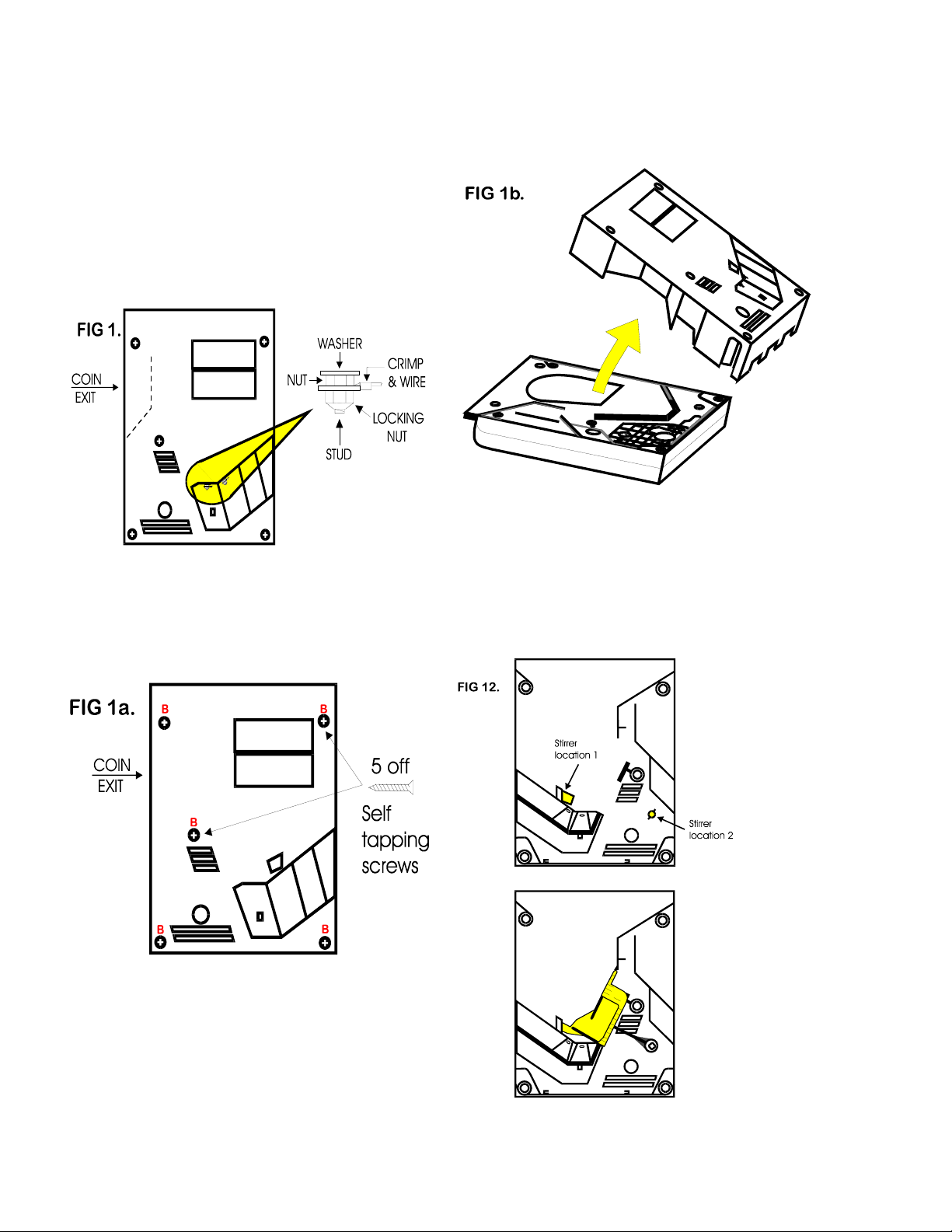
High voltage fuse: This is the primary transformer AC fuse
for the main logic board and the validator. Any direct short of
the Transformer or validator will cause this fuse to blow.
Replace this fuse with a 2-½ amp AS fuse only.
REPLACING THIS FUSE WITH ANYTHING OTHER
THAN A 2 ½ AMP “AS” MAY RESULT IN A FIRE OR AN
UNSAFE WORKING CONDITION!! (See fig. 1 for
location of this fuse.)
Low voltage fuse: This is the secondary transformer fuse for
the 5 - 28 vdc sections of the main logic board and hopper. It
is located to the left of the transformer. (See fig. 1) Replace
this fuse with a 2-½ amp AS fuse only. REPLACING THIS
FUSE WITH ANYTHING OTHER THAN A 2 ½ AMP
“AS” MAY RESULT IN A FIRE OR AN UNSAFE
WORKING CONDITION!!
Functional Description of the Series AC250Changer
To follow along with this walk-through of your changer, fill
the hopper with coins and turn the changer on.
1. When power is applied the out-of-service LED flashes
then goes out. The green LED on the main logic board
comes on steady, and the red LED on the main logic
board will light then go off then flicker on once per
second in the standby mode.
2. During the power-up mode the main logic board relay
clicks twice enabling power (120vac). When this relay is
not enabled it routes 12vdc ground to the out-of-service
LED. Without any power to the validator the changer
cannot accept bills. Since we are not in the error mode,
the red LED on the validator logic board is on steady.
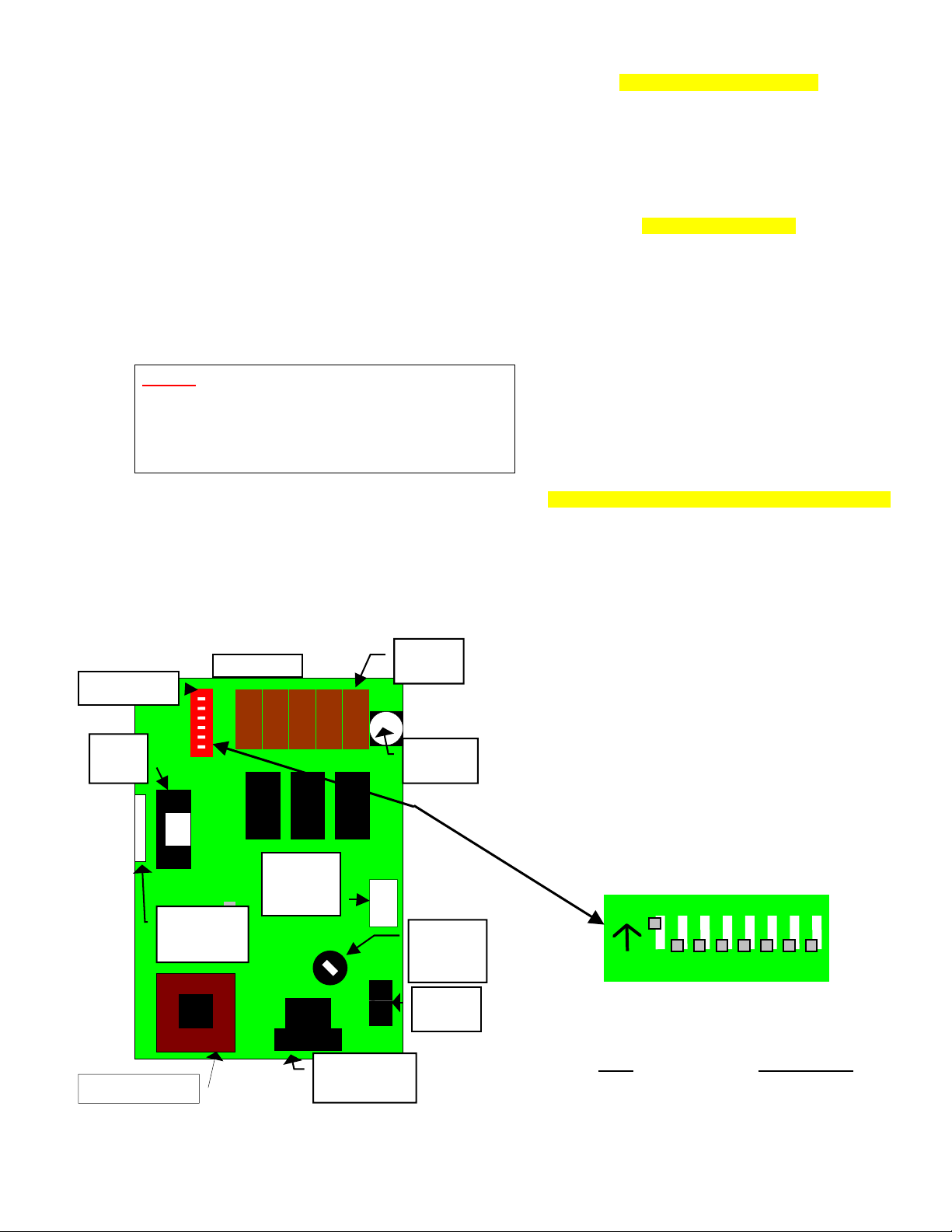
3. When the “Enter” button on the keypad is pressed it
grounds the 5vdc lines causing a pulse along the yellow
and blue validator harness wires to pins 5 and 15 of the
main logic board. Each pulse stands for the number on
the keypad display, i.e. 5 means the ground line was
pulsed 5 times.
4. The 5vdc pulse then travels from pins 5 and 15 to the
EPROM chip (MONO A-31) pin #25. The EPROM
sends a 12vdc pulse to the meter chip (U5) out pins #21
& 22 (one pulse per denomination validated ).The
EPROM also multiplies the ground pulse by the DIP
switch settings (The EPROM reads the DIP switch
settings during the power up mode and stores them into
memory.)
5. The EPROM then sends the hopper pulses out pin #23 to
pins 6 and 7 of the red 12-pin hopper plug. These pulses
travel through the purple and brown wires of the hopper
wire harness to the hopper pins 8 and 12.
6. The hopper turns itself on with the first hopper pulse.
The hopper counts the hopper pulses sent from the
EPROM chip on IN3 (pin 12) while dispensing the coins
at the same time. When the amount of hopper pulses in
equals the coins dispensed through the coin counting
optical sensor the hopper turns itself off.
7. The Changer returns to the standby mode with the red
LED flashing once per second until another bill is
inserted.
NOTE: THE METER ON THE MAIN LOGIC BOARD
CANNOT BE RESET TO ZERO!!!
Functional Descriptions of Out-of-Service Conditions
Out-of-Service conditions occur for the AC250 changer for
the following reasons; low coins, hopper fault error, validator
fault, or a blown fuse.
1. Blown Fuse: an AC power spike in line voltage or a bad
transformer on the main logic board can cause A blown
fuse on the main logic board. If either fuse blows the
indication is the green LED on the main logic board will
not light.
A. Replace the fuse. If the green LED now lights then
there was a spike.
B. If it does not and the fuse blows again the power
transformer is shorted. To test the transformer use a
voltmeter set for ohms and measure across the
primary (40ohms) and the secondary (1.5ohms).
2. Hopper Fault: A hopper fault can either be a jammed
hopper, a blocked coin counting optic or a bad hopper
logic board.
A. Indications for a jammed hopper are the changer
accepts bills, the meter counts up, but nothing or
not enough coins are paid out.
1. After 2 minutes the EPROM shuts off the
validator if the coins are not paid out correctly.
The “Empty” LED will flash once per second.
2. At this point the three options open are to
attempt repair on your own, call your
distributor, or return the hopper to American
Changer.
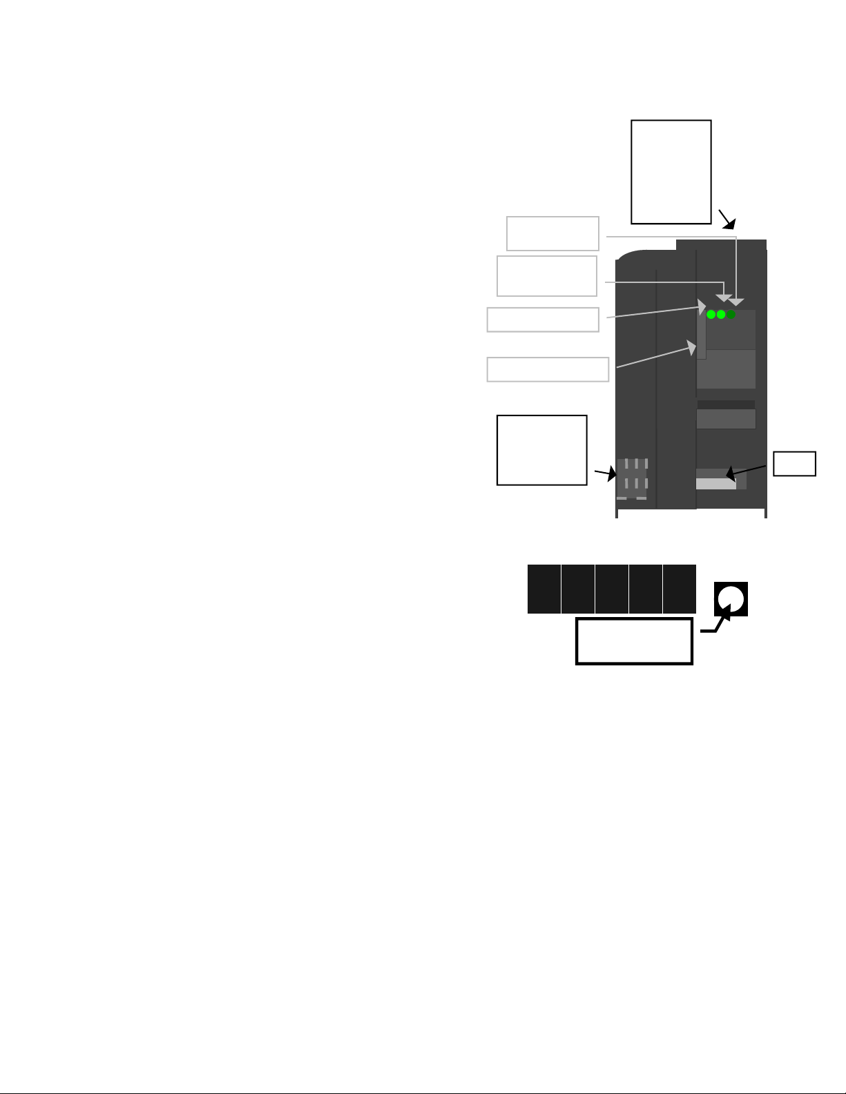
B. Indications for a blocked coin optic or bad hopper
logic board are the out-of-service LED on the
outside of the changer is lit and the red LED on the
main logic board is lit and flickers off once per
second.
1. If two of the 3 green LED’s on hopper logic
board are lit then the hopper logic board is
bad.
2. If there is a coin or foreign object caught in
the coin exit window LED’s #1 and #3 will
be lit on the hopper logic board instead of
LED’s #1 and #2.
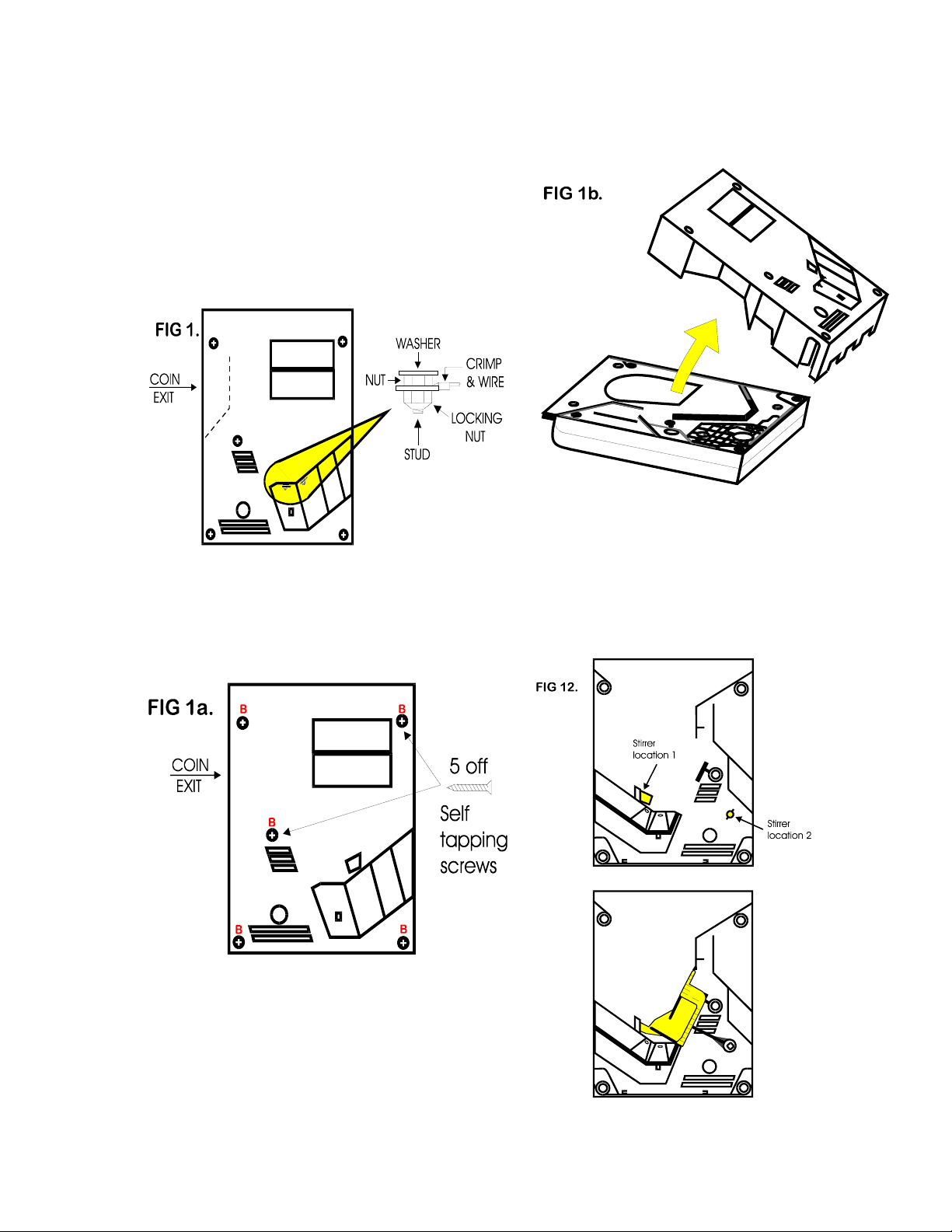
a. Take off the side of the hopper with 5
Philips screws. Pull up on the exit
window logic board and look for the
jammed item.
b. Ensure you have the pins aligned before
reconnecting logic board.
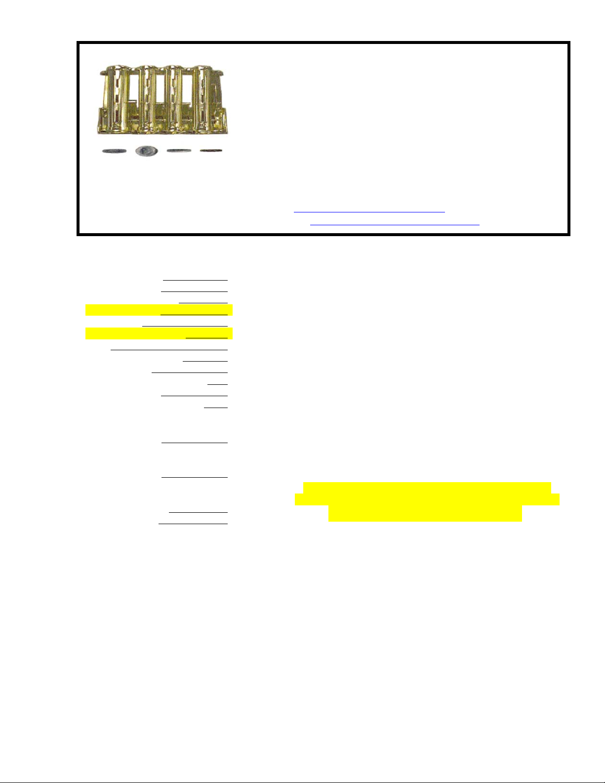
3. Low Coins: The low coin condition is probably the most
common fault. The EPROM on the main logic board is
constantly checking for low coins in the hopper. This is
done with a low current 5vdc signal on pin #3 of the
hopper output connector. The voltage then travels down
the hopper wire harness on the white wire to pin #7 of
hopper plug. The signal is applied to one of the gold low
contact plates at the bottom of the hopper. The 5v travels
through the coins through the other contact gold plate to