American DJ DMX OPERATOR User manual

American DJ®
DMX OPERATOR ™
User Instructions
DMX-512 MIDI
CAPABLE
American DJ Los Angeles, CA 90058 - DMX OPERATOR 2000

TABLE OF CONTENTS
FLOW CHART.....................................................................................................3
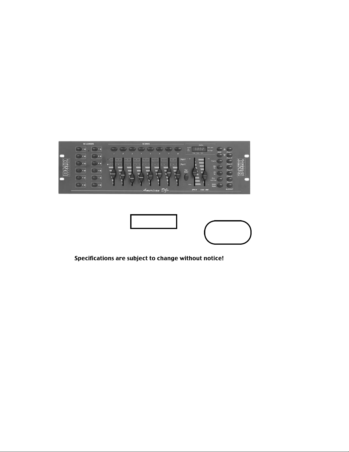
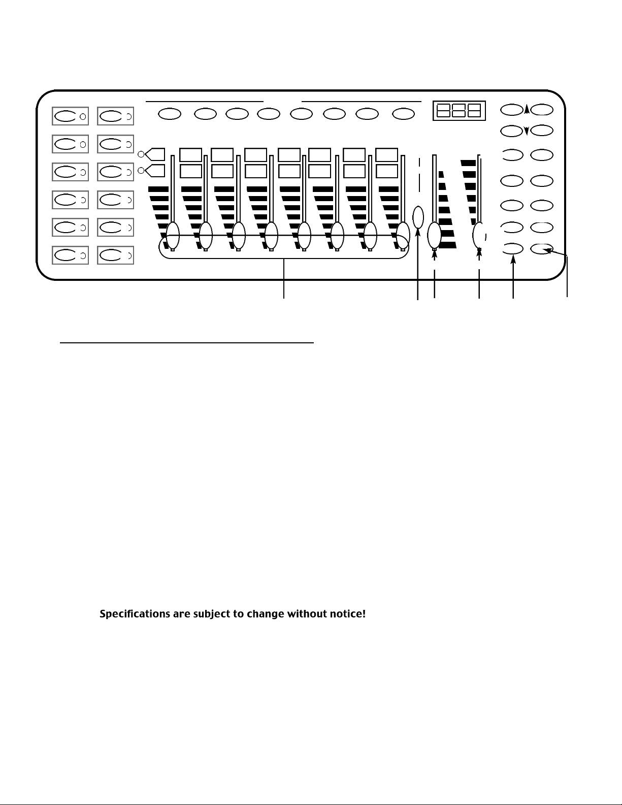
CONTROLS & FUNCTIONS.................................................................................4
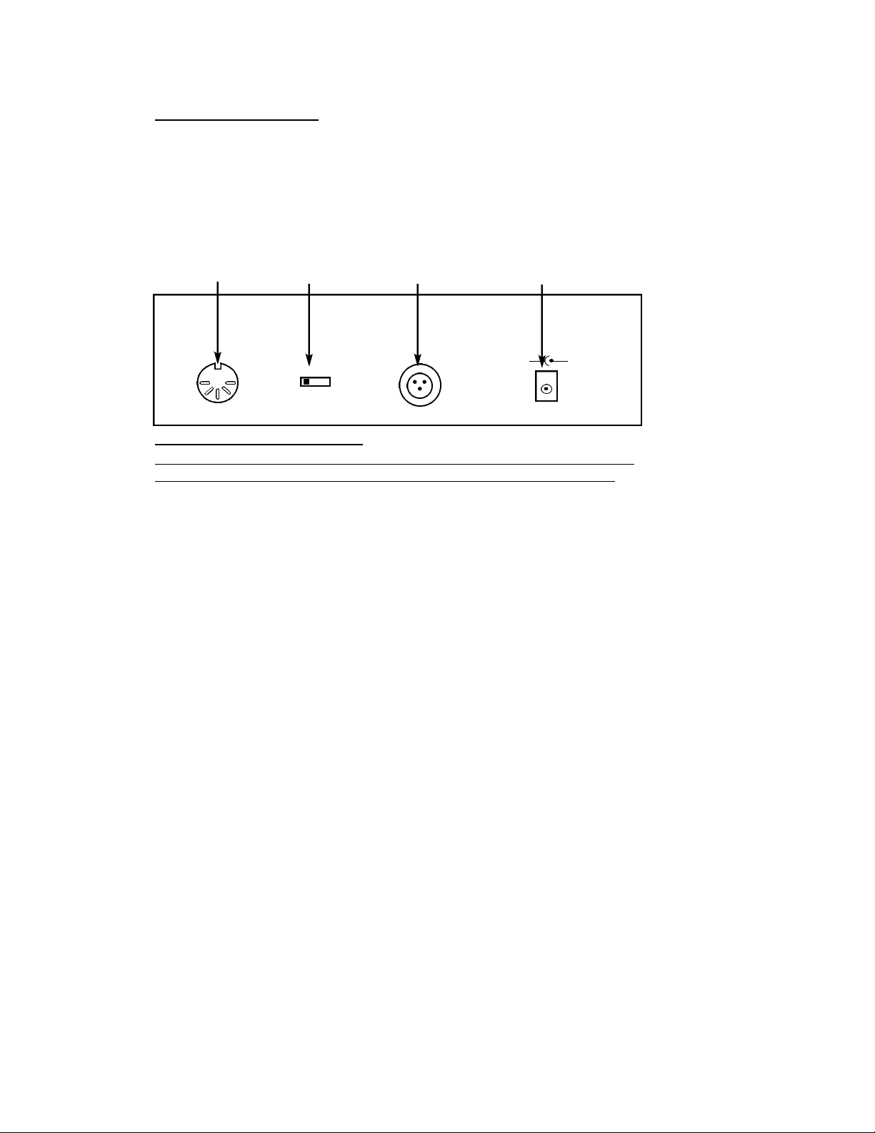
REAR CONTROLS ..............................................................................................6
DMX512 ADDRESSING......................................................................................6
PROGRAMMING SCENES................................................................................10
PROGRAMMING SCENES REVIEW:...............................................................11
SCENE COPY:................................................................................................12
SCENE EDITING:............................................................................................12
DELETE SCENE :.........................................................................................13
COPY BANK OF SCENES:.........................................................................13
DELETE BANK OF SCENES:........................................................................13
RESET ALL SCENES:....................................................................................13
PROGRAMMING CHASES:............................................................................ 14
EDITING CHASES............................................................................................14
INSERT A STEP:.........................................................................................14
DELETE A STEP:..........................................................................................15
DELETE A COMPLETE CHASE:...................................................................15
DELETE ALL CHASES:.................................................................................15
PLAYBACK SCENES & CHASES........................................................................16
MANUAL RUN SCENES:.............................................................................16
MANUAL RUN CHASES:............................................................................16
AUTO RUN SCENES:..................................................................................16
AUTO RUN CHASES:..................................................................................17
MUSIC RUN SCENES:.................................................................................17
MUSIC RUN CHASES:................................................................................17
MIDI OPERATION.............................................................................................18
CABLE TERMINATION............................................................................... 19
SPECIFICATION ............................................................................... 19
TROUBLE SHOOTING.......................................................................................20
DIP SWITCH DMX ADDRESS CHARTS.............................................................21

FLOW CHART
This is the order you program the DMX Operator.
ADDRESS
FIXTURES
pg 4 to 7
PROGRAM SCENES
(up to 240)
pg 8 & 9
PROGRAM CHASES
up to 6 of 240 scenes
pg 12
PLAYBACKCHASES
up to 240
pg 14
PLAYBACKSCENES
8 AT A TIME
30 BANKS OF 8
pg 14
American DJ Los Angeles, CA 90058 - DMX OPERATOR User Manual

1 2 3 4 5 6 7 8
1 2 3 4 5 6 7 8
9 10 11 12 13 14 15 16
123 4
9
5
6
7
8
SCENES
SCANNERS
BANK Chase 1
Chase 2
Chase 3
Chase 4
Chase 5
Chase 6
BLACKOUT
FADE TIME
SPEED
Display
Tapsync
Music
Bank-copy
Auto
Del
Midi
Rec
Program
Page
Select
Page A
Page B
1
2
4
3
5
12
11
10
9
8
7
6
CONTROLS & FUNCTIONS
1. SCANNER BUTTONS- Used to Select any or all of 12 fixtures This is
what selects which DMX channels go to the fixtures.
Scanner 1 controls Channel 1 to 16
Scanner 2 controls Channel 17 to 32
See addressing of fixtures on page 7 for more information
2. SCENE BUTTONS- Used to store Scenes in program mode or
playback your scenes in playback mode
3. LCD DISPLAY- Displays values and settings depending on the
chosen function.
4. BANK BUTTONS ( OR )- Selects which Bank you want to use.
(there are 30 selectable banks total.)
5. CHASE - Used to select chases (1-6).
6. PROGRAM - Used to activate program mode Display blinks when
activated.
7. MIDI / REC - Used to control MIDI operation or to Record each
step for Scene and Chases.
8. AUTO/DEL- Select AUTO speed in chase mode or Deletes Scenes
and or chases .
9. MUSIC / BANK COPY- Used to trigger sound activation in Chase
mode or to copy a bank of scenes from
one to another in Program Mode
American DJ Los Angeles, CA 90058 - DMX OPERATOR User Manual

CONTROLS & FUNCTIONS CONTINUED
10. BLACKOUT - Disables or enables all channel outputs
11. TAP SYNC / DISPLAY - In Auto Chase mode used to change rate
of chase also to change LCD Display in
Manual Chase.
12. FADE TIME SLIDER - Used to adjust the FADE TIME. Fade Time is
the amount of time it takes the DMX Operator to completely
change from one scene to another.
For example; if the fade time slider is set to 0 (zero) a scene change
will be instant. If the slider is set to ‘30s’ it will take the DMX Operator
30 seconds to complete the change from one scene to the next.
13. SPEED SLIDER- Used to adjust the rate of chase speed in Auto
Mode.
14. PAGE SELECT- Used to select faders between PAGE A (1-8) and
PAGE B (9-16) of each Scanner Button
15. FADERS (1-8)- Used to adjust the intensity from 0% to 100% or DMX
output level from 0 to 255 of each channel
American DJ Los Angeles, CA 90058 - DMX OPERATOR User Manual
1 2 3 4 5 6 7 8
1 2 3 4 5 6 7 8
9 10 11 12 13 14 15 16
12 11 101315 14
SCENES
SCANNERS
BANK Chase 1
Chase 2
Chase 3
Chase 4
Chase 5
Chase 6
BLACKOUT
FADE TIME
SPEED
Display
Tapsync
Music
Bank-copy
Auto
Del
Midi
Rec
Program
Page
Select
Page A
Page B
1
2
4
3
5
12
11
10
9
8
7
6

REAR CONTROLS
16. MIDI IN- Receives MIDI data.
17. DMX POLARITY SELECT- Changes the polarity setting of the DMX
output.
18. DMX OUT- Used to send DMX signal to fixtures or Packs.
19. DC INPUT- Accepts a DC 9~12V, 300 mA minimum, power
supply.
+9V-+12V 300mA Min.
DC INPUT
+-
1:GND
2:DATA -
3:DATA +
1:GND
2:DATA +
3:DATA -
DMX OUT
DMX POLARITY
SELECT
MIDI IN
16 17 18 19
DMX512 ADDRESSING
WHEN ADDRESSING YOUR FIXTURES FOLLOW THE STARTING ADDRESS IN
THIS BOOK NOT THE ADDRESSING FOUND IN YOUR FIXTURE MANUAL
DMX 512 is a type of protocol that sends out up to 512 multiplex
channels at once down a common cable. Each channels has a
value from 0 to 255. You set the address for each receiver(fixture) by
using Dip switches or some type of digital readout
While DMX 512 is the standard used to control lighting, at this time,
there are some differences you should know about. One is pin con-
figuration. The DATA + And DATA- are reversed. This can be corrected
by using the reversal switch on the DMX Operator. If you have some
fixtures from each polarity use adapter Z-DMXADAPT between the
fixtures.
Each Dip switch has an ADDRESS based on binary code.
Dip switch #1 #2 #3 #4 #5 #6 #7 #8 #9
Value 1 2 4 8 16 32 64 128 256
YOU SELECT THE ADDRESS WANTED BY ADDING THE TOTAL OF DIP
SWITCHES ON.
Dip switch #10 is not used with DMX but normally to select some
Function ie: Master / Slave, Sound Activation or to receive DMX
Control.
American DJ Los Angeles, CA 90058 - DMX OPERATOR User Manual

American DJ Los Angeles, CA 90058 - DMX OPERATOR User Manual
Most fixtures start receiving on the address selected
EXAMPLE:
Setting ADDRESS at 1 unit starts at CHANNEL 1
Dip switch # 1 on
Setting ADDRESS for Setting ADDRESS for
17 unit starts at 49 unit starts at
CHANNEL 17 CHANNEL 49
Dip switch # 1 = 1 Dip switch # 1 = 1
“# 5 = +16 “ 5 = 16
= 17 “6 = 32
= 49
DIP SWITCH DMX ADDRESS
1 2 3 54 7 9 1086
ON
1 4 16 64 256
2 8 32 128 DIP SWITCH DMX ADDRESS
1 2 3 54 7 9 1086
ON
1 4 16 64 256
2 8 32 128
Dip switch total = 17
unit starts at
CHANNEL 17
Dip switch total = 49
unit starts at
CHANNEL 49

American DJ Los Angeles, CA 90058 - DMX OPERATOR User Manual
Some units start receiving one more than the ADDRESS selected.
Example Max,Patend Light,Mighty Scan
EXAMPLE:
Setting ADDRESS at 0 unit starts at CHANNEL 1 all Dip switches OFF
Setting ADDRESS for Setting ADDRESS for
17 49
Dip switch # 5 = 16 Dip switch # 5 = 16
= 16 6 = 32
= 48
unit starts at 17 unit starts at 49
DIP SWITCH DMX ADDRESS
1 2 3 54 7 9 1086
ON
1 4 16 64 256
2 8 32 128 DIP SWITCH DMX ADDRESS
1 2 354 7 9 1086
ON
1 4 16 64 256
2 8 32 128
Dip switch total = 16
unit starts at
CHANNEL 17
Dip switch total = 48
unit starts at
CHANNEL 49

TYPE 1
DATA IN
XLR MALE SOCKET
3 Data -
Data+ 2
1 Ground
TYPE 2
DATA IN
XLR MALE SOCKET
3 Data +
Data - 2
1 Ground
Addressing Fixtures
In order to have individual control of each fixture with
the DMX operator Fixture addresses should be addressed
as follows.
Scanner Button # 1 starts at 1
Scanner Button # 2 starts at 17
Scanner Button # 3 starts at 33
Scanner Button # 4 starts at 49
Scanner Button # 5 starts at 65
Scanner Button # 6 starts at 81
Scanner Button # 7 starts at 97
Scanner Button # 8 starts at 113
Scanner Button # 9 starts at 129
Scanner Button # 10 starts at 145
Scanner Button # 11 starts at 161
Scanner Button # 12 starts at 177
If you are not sure how to set the starting address of your
Fixture refer to Chart on pages 20 & 21 of manual.
American DJ Los Angeles, CA 90058 - DMX OPERATOR User Manual

PROGRAMMING SCENES:
1. PRESS AND HOLD PROGRAM BUTTON (FIG. 6) for three (3) seconds
to activate program mode. The LCD DISPLAY (FIG.3)will indicate
your in program mode by displaying a continuous fast blinking
light next to ‘PROG.
2. Select a fixture to program, by pressing any or all SCANNER BUTTONS
1 TO 12 (FIG2). Each Scanner Button controls 16 DMX channels,
Faders 1 - 8 on PAGE A and 9 - 16 on PAGE B (FIG. 14).
3. Adjust the faders to the desired settings of the fixture or fixtures your
programming (i.e. Color, Gobo, Pan, Tilt, Speed, etc.), by adjusting
the fader values. Use the PAGE A B BUTTON if your Fixture has more
than eight channels. When selecting from Page A to B you have to
move Sliders to activate channels
4. Once you’ve reached your desired setting and or position for the
Fixture, you can press the SCANNER BUTTON you were adjusting this
stops adjustment of that Fixture(s). You then press another SCANNER
BUTTON to select another Fixture to adjust.You can adjust more than
one fixture at a time by selecting more than one Scanner Button at
a time
5. Repeat steps 2,3and until all the lights are at the setting you want.
6. When entire scene is set to your liking, press and release the
MIDI / REC BUTTON (FIG 7.) ALL LEDS BLINK 3 TIMES.
8. Then press a SCENE BUTTON 1-8 (FIG 2) to store this scene. The LCD
will display the bank and scene to where your scene was stored.
9. Repeat steps 2-8 to record your first 8 scenes.
10. Now select the bank you want to store your next 8 scenes into by
using the UP and DOWN BANK BUTTONS (FIG.4).
There are 30 banks you can store up to 8 scenes per a bank for a
total of 240 scenes.
11. To exit programming mode press and hold the PROGRAM BUTTON
(FIG.6) for 3 seconds.
When you exit programming Blackout LED is on press BLACKOUT BUTTON
to de-activate blackout.
American DJ Los Angeles, CA 90058 - DMX OPERATOR User Manual

PROGRAMMING SCENES REVIEW
To review this is how you would create a simple 4 step box pattern
1. Press and hold PROGRAM BUTTON (FIG. 6) for three (3) seconds
2. Select a fixture(s) to program using the SCANNER BUTTONS 1 TO 12
NOTE: WHEN YOU ARE BEGINNING IT MAY BE EASIER TO USE FOUR
CUPS OR OTHER OBJECTS PLACED ON THE FLOOR AS A GUIDE.
3. Adjust the faders to the desired Color, Gobo, then using the Pan, Tilt,
adjust the mirrors to go to the bottom corner of the dance floor.
4. Press and release the MIDI / REC BUTTON (FIG 7.).
5. Then press SCENE BUTTON 1ALL LEDS BLINK 3 TIMES
6. Adjust the Pan faders to adjust the mirrors to go across to the other
bottom corner of the dance floor.
7. Press and release the MIDI / REC BUTTON (FIG 7.).
8. Then press SCENE BUTTON 2 ALL LEDS BLINK 3 TIMES
9. Adjust the tilt fader to adjust the mirrors to go up to the top corner
of the dance floor.
10. Press and release the MIDI / REC BUTTON (FIG 7.).
11.Now press SCENE BUTTON 3 ALL LEDS BLINK 3 TIMES
12. Adjust the Pan fader to adjust the mirrors to go across to the other
top corner of the dance floor.
By pressing Scene buttons 1 to 4 in
order you should have a box pattern. If you have a problem refer
to Trouble shooting. page??
You can now use these scenes to make scenes 5-8 Same box
patterns with different colors and gobos
1. Press SCENE BUTTON 1 make color and gobo adjustments
2. Press and release the MIDI / REC BUTTON (FIG 7.).
3. Then press SCENE BUTTON 5 ALL LEDS BLINK 3 TIMES
4. Press SCENE BUTTON 2 make color and gobo adjustments
5. Press and release the MIDI / REC BUTTON (FIG 7.).
6. Then press SCENE BUTTON 6 ALL LEDS BLINK 3 TIMES
7. Press SCENE BUTTON 3 make color and gobo adjustments
8. Press and release the MIDI / REC BUTTON (FIG 7.).
9. Then press SCENE BUTTON 7 ALL LEDS BLINK 3 TIMES
10. Press SCENE BUTTON 4 make color and gobo adjustments
11. Press and release the MIDI / REC BUTTON (FIG 7.).
13. Then press SCENE BUTTON 8 ALL LEDS BLINK 3 TIMES
THIS GIVES YOU 8 SCENES 2 DIFFERENT
COLORED BOX PATTERNS.
ONCE YOU HAVE RECORDED ALL THE SCENES
YOU CAN NOW GO TO
PROGRAMMING CHASES PG 12
American DJ Los Angeles, CA 90058 - DMX OPERATOR User Manual
1 2
4 3

Programming Scenes continued
SCENE COPY:
This function allows you to copy the settings of one scene to another.
1. Press the PROGRAM BUTTON (FIG. 6) for three (3) seconds to
activate program mode. The LCD DISPLAY(FIG.3) will indicate
program mode by displaying a continuous fast blinking dot next
to ‘PROG.’
2. Use the UP and DOWN BANK BUTTONS (FIG.4) to locate the bank
that contains the scene you wish to copy.
3. Press the SCENE BUTTON (FIG.5), that contains the scene you want to
copy.
4. Use the UP and DOWN BANK BUTTONS (FIG.4) to select the bank you
want to copy the scene to.
5. Press the MIDI / REC BUTTON (FIG.7) followed by the SCENE BUTTON
(FIG.5) you wish to copy to.
SCENE EDITING:
This function allows you to make changes in a scene after it has been
programmed.
1. Press the PROGRAM BUTTON (FIG. 6) for three (3) seconds to
activate program mode. The LCD DISPLAY(FIG.3) will indicate
program mode by displaying a continuous fast blinking dot next
to ‘PROG.’
2. Use the UP AND DOWN BANK BUTTONS (FIG.4) to select the bank
that stores the scene you wish to edit.
3. Select the scene you want to edit by pressing its SCENE BUTTON
(FIG.5).
4. Use the FADERS (FIG.15) to make your desired adjustments.
5. Once you’ve made your changes, press the MIDI / REC BUTTON
(FIG.7) followed by the SCENE BUTTON (FIG.2) that corresponds to
the scene your editing. This will store the edited scene back into
memory.
Be sure to selected the same scene you selected in step 4, other -
wise you may accidentally record over an existing scene.
American DJ Los Angeles, CA 90058 - DMX OPERATOR User Manual

COPY BANK OF SCENES:
This function will copy the settings of one bank to another.
1. Press the PROGRAM BUTTON (FIG. 6) for three (3) seconds to
activate program mode. The LCD DISPLAY (FIG.3)will indicate
program mode by displaying a continuous fast blinking dot next
to ‘PROG.’
2. Select the BANK (FIG.4) you want to copy
3. Press and release the MIDI/REC BUTTON (FIG.7)
4. Select the BANK (FIG.4) you wish to record to.
5. Press MUSIC/BANK COPY BUTTON (FIG.9), The LCD DISPLAY (FIG.3)
will flash briefly to indicate the function has been completed.
DELETE BANK OF SCENES:
1. Select the BANK (FIG.4) you want to delete
2. Press and hold the AUTO/DEL BUTTON (FIG.8).
3.While holding down the AUTO/DEL BUTTON (FIG.8) press and hold
the MUSIC/BANK COPY BUTTON (FIG.9) at the same time.
4. Release both buttons at the same time, the LCD DISPLAY (FIG.3)
should flash momentarily to indicated the function completion.
DELETE SCENE :
This function will reset all DMX Channels in a single SCENE back to 0.
1. While pressing and holding AUTO/DEL(FIG.8), Press and release the
SCENE BUTTON (FIG.2) 1-8 you want to delete.
RESET ALL SCENES:
This function will erase all scenes in all Banks
(ALL Channels of all scenes are reset to 0 output).
1. Press and hold down the PROGRAM button (fig.6)
2. While holding down the PROGRAM BUTTON (FIG.6), press and hold
the BANK DOWN BUTTON (FIG.4).
3. Disconnect the power and release the buttons.
4. Reconnect the power, all scenes should be erased
American DJ Los Angeles, CA 90058 - DMX OPERATOR User Manual

PROGRAMMING CHASES:
NOTE: YOU MUST PROGRAM SCENES BEFORE YOU CAN PROGRAM CHASES.
1. Press the PROGRAM BUTTON (FIG. 6) for three (3) seconds to
activate program mode. The LCD DISPLAY(FIG.3) will indicate
program mode by displaying a continuous fast blinking dot next
to ‘PROG.’
2. Select any CHASE 1 TO 6 (FIG 5) to program.
3. Select a desired SCENE (FIG2) from any bank that has been
previously recorded.
4. Press the MIDI/REC BUTTON (FIG.7). All LED’s blink 3 times
5. Repeat steps 3 & 4 as many times as you want.
You may store up to 240 steps into one chase.
6. To exit programming press the PROGRAM BUTTON (FIG. 6) for
three (3) seconds to de-activate program mode. The LCD
DISPLAY(FIG.3) will indicate blackout mode by displaying a
continuous fast blinking dot next to ‘Blackout.’
You May now playback the Chase Recorded Pg. 14
EDITING CHASES
INSERT A STEP:
1. Press the PROGRAM BUTTON (FIG. 6) for three (3) seconds to
activate program mode. The LCD DISPLAY(FIG.3) will indicate
program mode by displaying a continuous flashing light next to
‘PROG.’
2. Select the CHASE 1 TO 6 (FIG 5) you wish to add a step to.
3. Press and release the TAP SYNC/DISPLAY BUTTON (FIG.11).
The Display will now change to the step you are now in.
4. After selecting the TAP SYNC/DISPLAY (FIG.11) use the UP and
DOWN BUTTONS, to manually scroll to the STEP you wish to insert a
step after.
5. Press MIDI/REC (FIG.7) the LCD will read one step number higher
6. Press the Scene Button you want to insert
6. Press MIDI/REC (FIG.7) again to insert new step.
7. Press and release the TAP SYNC/DISPLAY (FIG.11) to return the dis
play to normal operation.
American DJ Los Angeles, CA 90058 - DMX OPERATOR User Manual

DELETE A STEP:
1. Press the PROGRAM BUTTON (FIG. 6) for three (3) seconds to
activate program mode. The LCD DISPLAY (FIG.3) will indicate
program mode by displaying a continuous flashing light next to
‘PROG.’
2. Select the CHASE 1 TO 6 (FIG. 5) that contains the step you would
like to delete.
3. Press and release the TAP SYNC/DISPLAY (FIG.11).
4. After selecting the TAP SYNC/DISPLAY (FIG.11) use the UP and
DOWN BUTTONS, to manually scroll to the step you wish to delete.
5. When you have reached the step you wish to delete, press and
release the AUTO/DEL (FIG.8).
DELETE A COMPLETE CHASE:
1. Press and hold down the CHASE BUTTON (FIG.5) that you want to
delete.
2. While holding down the CHASE BUTTON (FIG.5) press and release
the AUTO/DEL BUTTON (FIG. 9).
3. Release the CHASE BUTTON (FIG.5). The chase should be deleted.
DELETE ALL CHASES:
This function will allow you to clear all chase memory
(delete all chases).
1. Press and hold down the AUTO/DEL BUTTON (FIG.8).
2. While holding down the AUTO/DEL BUTTON (FIG.8) disconnect the
power.
3. Holding down the AUTO/DEL BUTTON (FIG.8) reconnect the
power hold for 3 seconds LED’s blink all chase memory should be
erased.
American DJ Los Angeles, CA 90058 - DMX OPERATOR User Manual

PLAYBACK SCENES & CHASES
MANUAL RUN SCENES:
1. When power is first turned on, the unit is in manual scene mode.
2. Make sure AUTO & MUSIC LED’S BUTTONS (FIGS. 8 AND 9) are off .
3. Select BANK (FIG.4), using the UP and DOWN BANK BUTTONS
(FIG.4), that store the scenes you wish to run.
4. Press the SCENE BUTTONS (FIG.2) to run the scene you selected.
MANUAL RUN CHASES:
This function will allow you to manually step through all scenes in
any Chase.
1. Press the PROGRAM BUTTON (FIG. 6) for three (3) seconds to
activate program mode. The LCD DISPLAY(FIG.3) will indicate
program mode by displaying a continuous fast blinking dot next
to ‘PROG.’
2. Execute a chase by selecting one of the eight CHASE BUTTONS
(FIG.5).
5. Press the TAP/SYNC BUTTON (FIG.11).
6. Use the BANK BUTTONS (FIG.4) to scroll through the chase.
Note:Display will show the number of the step in the Chase not
the Scene bank or number
AUTO RUN SCENES:
This function will run a bank of programmed scenes in a sequential
loop.
1. Press the AUTO/DEL (FIG.8) to activate Auto Mode. A flashing
light in the LCD DISPLAY (FIG.3) will indicate auto mode.
2. Use the UP and DOWN BANK BUTTONS (FIG.4), to select a bank of
scenes to run.
3. After selecting the bank of scenes you want run, you can use the
SPEED (FIG.13) and FADE (FIG.12) sliders to adjust the scene chase
Note: you can change banks, to run different scene sequences,
at any time by pressing the UP and DOWN BANK BUTTONS (FIG.4).
Note: when Adjusting fade time never make it slower than the
Speed setting or your scene will not be completed before a new step
is sent.
American DJ Los Angeles, CA 90058 - DMX OPERATOR User Manual

AUTO RUN CHASES:
1. Select your desired chase by pressing any or all of the six
CHASE BUTTONS (FIG.5).
2. Press and release the AUTO/DEL BUTTON (FIG.8).
3. The corresponding LED will flash in the LCD DISPLAY (FIG.3)
indicating Auto mode is engaged.
4. Adjust the SPEED (FIG.13) and FADE (FIG.12) times to your desired
settings.
5. The chase will now run according to your set speed and fade
time.
Note: You can override the speed and by tapping the
TAP SYNC /DISPLAY BUTTON (FIG.11) three times, the chase would
then run according to the time interval of your taps.
Note: when Adjusting fade time never make it slower than the Speed
setting or your scenes will not be completed before a new step is
sent.
Note: If you want to include all the Chases PRESS AUTO/DEL BUTTON
before selecting Chase.
MUSIC RUN SCENES:
1. Press the MUSIC/BANK-COPY BUTTON (FIG.9) to turn on the
corresponding LED in the LCD DISPLAY (FIG.3).
2. Select the bank that holds the scenes you wish to chase by using
UP or DOWN BUTTONS (FIG.4), you may also use a MIDI controller
to change the scenes (see MIDI operation).
3. Press MUSIC/BANK COPY BUTTON (FIG.9) to exit.
MUSIC RUN CHASES:
1. Select your desired chase by pressing one of the six
CHASE BUTTONS (FIG.5).
2. Press and release the MUSIC/BANK-COPY BUTTON (FIG.9).
3. The corresponding LED will flash in the LCD DISPLAY (FIG.3)
indicating Music mode is engaged.
4. Chase will now run sound.
American DJ Los Angeles, CA 90058 - DMX OPERATOR User Manual

MIDI OPERATION
To Activate MIDI operation:
1. Press and hold down the MIDI/REC BUTTON (FIG.7) for three
seconds, the last two digits of the LCD DISPLAY (FIG.3)will BLINK to
indicate MIDI setting.
2. Use the UP AND DOWN BUTTONS (FIG.4) to select the MIDI
Channel 1 to 16 you would like to be activated from.
3. Press and hold down the MIDI/REC BUTTON (FIG.7) for three
seconds,to exit this function and MIDI operation is now on.
MIDI CHANNEL SETTING
BANK (Octave) NOTE NUMBER FUNCTION
BANK 1 00 TO 07 1 to 8 of Bank 1 on or off
BANK 2 08 TO 15 1 to 8 of Bank 1 on or off
BANK 3 16 TO 23 1 to 8 of Bank 1 on or off
BANK 4 24 TO 31 1 to 8 of Bank 1 on or off
BANK 5 32 TO 39 1 to 8 of Bank 1 on or off
BANK 6 40 TO 47 1 to 8 of Bank 6 on or off
BANK 7 48 TO 55 1 to 8 of Bank 7 on or off
BANK 8 56 TO 63 1 to 8 of Bank 8 on or off
BANK 9 64 TO 71 1 to 8 of Bank 9 on or off
BANK 10 72 TO 79 1 to 8 of Bank10 on or off
BANK 11 80 TO 87 1 to 8 of Bank11 on or off
BANK 12 88 TO 95 1 to 8 of Bank12 on or off
BANK 13 96 TO 103 1 to 8 of Bank13 on or off
BANK 14 104 TO 111 1 to 8 of Bank14 on or off
BANK 15 112 TO 119 1 to 8 of Bank14 on or off
CHASES 120 TO 125 1 to 6 Chases
BLACK OUT 126 BLACKOUT
American DJ Los Angeles, CA 90058 - DMX OPERATOR User Manual

American DJ Los Angeles, CA 90058 - DMX OPERATOR User Manual
Specifications
All Scenes,Chases, and Options retained by battery back up
3 space 19” rackmount case
Reversible DMX polarity out put
MIDI input to control Chase and scene s
192 DMX Channels output 12 Scanners buttons (up to 16 Channels
each)
6 Chases of 240 steps
240 Scenes in 30 Banks
Audio Chase
Speed and Fade time adjustments
CABLE TERMINATION
When total run of Control cable is 90” or over it is necessary to terminate
the Cable. This can be accomplished as follows.
1: Many Fixtures have some type of built in termination either auto
matic or by some type of function switch,select this in the last fixture in
the link.
2: Make or buy a Termination Plug and insert it into the last Fixture in the
link.
To make a termination plug use a Male XLR plug and solder a 90 to 120
ohm 1/4 watt resistor between pins 2 & 3 of the plug.

American DJ Los Angeles, CA 90058 - DMX OPERATOR User Manual
TROUBLE SHOOTING.
Mirrors don’t respond when I move faders
Make sure address is correct. See Chart pages 20, 21
Make sure speed is adjusted, if available, for faster
movement.Not all Fixtures have a speed adjustment.
If total of XLR cable is more than 90 feet make sure it is
terminated properly.
Colors don’t respond when I move faders
Make sure address is correct. See Chart pages 20 21
If total of XLR cable is more than 90 feet make sure it is
terminated properly.
Scenes don’t playback after I record them
Make sure to press MIDI/RECORD BUTTON, before pressing
SCENE BUTTON. LED’s should blink after pressing each
SCENE BUTTON.
Make sure you are in the correct Bank that has scenes
recorded.
Scenes don’t playback correctly like I recorded them
Was Scanner for all fixtures recorded.
Is Fade Time to long for Speed selected?
Make sure you are in the correct Bank that has scenes
recorded
If total of XLR cable is more than 90 feet make sure it is
terminated properly.
Chases don’t playback after I record them
Make sure to press MIDI/RECORD BUTTON, after pressing
SCENE BUTTON. LED’s should blink after pressing MIDI/RECORD
BUTTON.
Make sure you are in the correct Chase that has steps
recorded
If in Auto Mode, is It selected in Display. Did you adjust Speed
after selecting Auto?
Is Fade Time to long for Speed Selected?
If total of XLR cable is more than 90 feet make sure it is
terminated properly.
This manual suits for next models
1
Table of contents
Other American DJ Control System manuals
Popular Control System manuals by other brands

Soyal
Soyal AR-716-E16 Parameter-setting manual

Continental Refrigerator
Continental Refrigerator E-Access WI2427LF installation instructions

Simon
Simon Scena Manual and installation guide

IDEAL INDUSTRIES
IDEAL INDUSTRIES Audacy Wireless Controls user manual

Basler
Basler DECS-100 instruction manual

Valeo
Valeo SC600 Marcopolo operating instructions