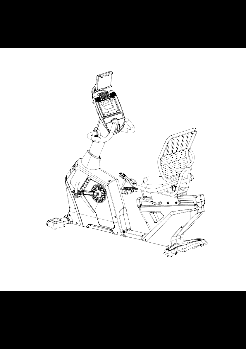
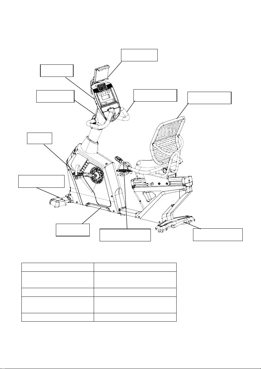
American Fitness R11-V2 User manual

Thank you
Owner’s Manual
Retain this owner’s manual for future reference
Read and follow all instructions in this owner’s manual
Version A
1

Thank you
Thanks for purchasing this product. The product will help you exercise your muscles in the
correct way and to improve your fitness – and all this in a familiar environment.
Precautions
WARN NG: This exercise bike has been designed and constructed to provide maximum
safety. Nevertheless, certain precautions should be taken when using exercise equipment.
Read the whole manual before assembling and using the exercise bike. The following safety
precautions should also be observed: The exercise bike has been designed and constructed
◆This appliance can be used by children aged from 8 years and above and persons with
reduced physical, Sensory or mental capabilities or lack of experience and knowledge if
they have been given supervision or nstruction concerning use of the appliance in a safe
way and understand the hazards involved.
◆Children should not play with the appliance. Cleaning and user maintenance shall not be
made by children without supervision.
◆t is the responsibility of the owner to ensure that all users of the exercise bike are
adequately informed of all precautions.
◆Keep children and pets away from the exercise bike at all times.DO NOT leave them
unsupervised in the room where this exercise bike is kept.
◆nspect and tighten all parts regularly. Replace defective components immediately and/or
keep the equipment out of use until repair. The safety level of the equipment can be
maintained only if it is examined regularly for damage and wear.
◆Place the exercise bike on a level surface, with at least 1.0 m of clearance on each side of
elliptical. To protect the floor or carpet from damage, place a mat under the exercise bike.
◆Keep the exercise bike indoors, away from moisture and dust. Do not put the exercise
bike in a garage or covered patio, or near water.
◆Don’t put any sharp things around the exercise bike.
◆Wear appropriate clothes while exercising; do not wear loose clothes that could become
caught on the exercise bike. Always wear athletic shoes for foot protection while
exercising.
◆Do not put your hands on the moving parts to prevent injures.
◆Keep your pedaling speed in a controlled way. Exercise Bike is speed independent
training equipment, it can also be adjusted by other means than speed.
◆f you find your exercise bike works abnormal, do not use it immediately.
◆No more than one person should operate the exercise bike at one time.
◆WARN NG! Heart rate monitoring systems may be inaccurate. Over exercising may result
in serious injury or death. f you feel pain or faint while exercising, stop exercising
immediately and ask for a doctor.
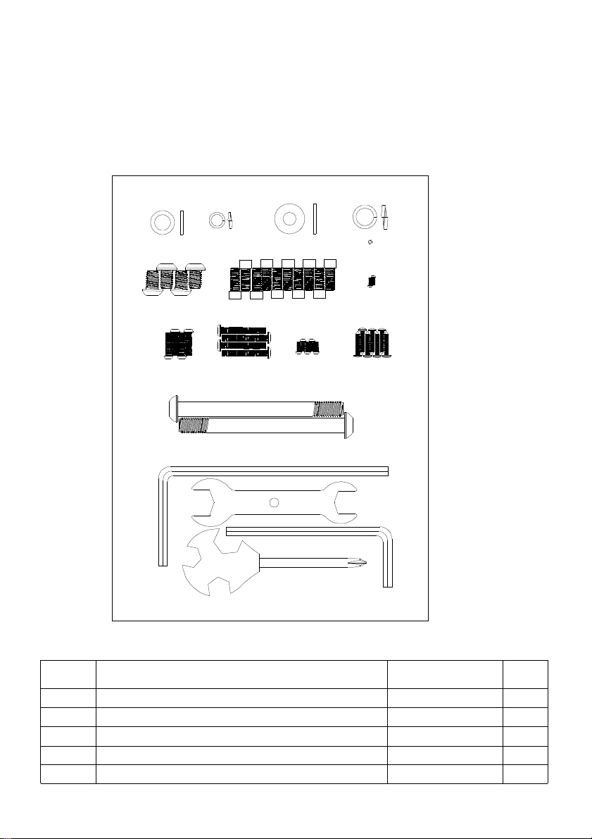
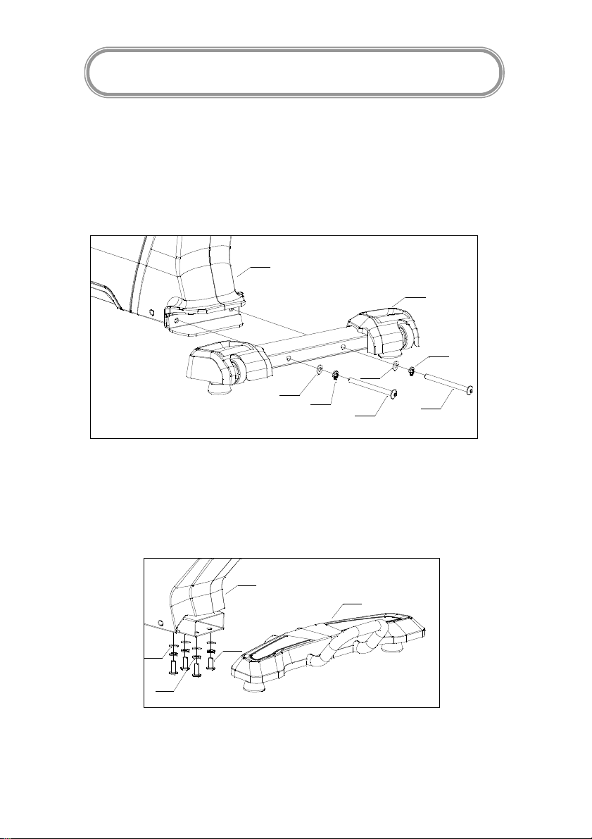
2

Safety notice
When you are remedial or have below symptoms, after discussing with your doctor, then
could use this treadmill.
1. Waist paining now and leg, waist, neck hurt before, legs, waist, neck and hand numbly
please not use
2. Have anamorphic arthritis, rheumatic and gouty
3. Have osteoporosis exceptional
4. Have perfunctory system obstacle (heart disease, blood obstacle, hypertension )
5. Have breath obstacle
6. Using the manpower pulse adjust machine or insert into the body machine
7. Have sarcomata
8. Have thrombus or other symptoms
9. Have diabetes or be caused by diabetes feeling obstacle
10. Have skin broken
11. Sicken caused hyperpyrexia (38 ℃over 38 ℃)
12. Back bone exceptional or back bone bend
13. Pregnant or Menstrual period
14. Feel body exceptional, need convalesce
15. Body condition not very well
16. The aim is to healing
17. Except the upper symptoms, the body feel exceptional.
----Maybe cause the accident or cause the body condition not very well
Before beginning any exercise program, consult your physician. This is especially
important for persons over age 35 or persons with pre-existing health problems. To
reduce the risk of serious injury, read all important precautions and instructions in this
manual and all warnings on your exercise bike before using your exercise bike.
3

PRE-ASSEMBLY NOTES
pen The Boxes
Make sure to inventory all the parts that are included in the box. Check the hardware chart of
a full count of the number of parts included for proper assembly . f any of the parts are
missing, contact with the dealer.
N . NAME SPECIFICATI N QTY
19 Allen C.K.S. full thread bolt M10×20 4
20 Allen cylindrical head full thread bolt M8x20 10
23 Allen C.K.S. half thread bolt M10x110x20 2
25 Allen C.K.S. full thread bolt M6×15 4
28 Phillips pan head full thread bolt M4×10 2
43 Φ8-3 41 Φ8-3
20 M8*20-10
42 10-6
44 Φ10-6
36 M5×15-5
19 M10×20-4
38 ST4×16-7
R11-V2
23 M10*110*20-2
25 M6×15-4
28 M4×10-2
29 M6×30-4
4

GATHER Y UR T LS
Before starting the assembly of your unit ,gather the necessary tools. Having all of the
equipment at hand will save time and make the assembly quick and hassle-free.
CLEAR Y UR W RK AREA
Make sure that you have cleared away a large enough space to properly assemble the unit.
Make sure the space is free from anything that may cause injury during assembly. After the
unit is fully assembled, make sure there is a comfortable amount of free area around the unit
for unobstructed operation.
N TE: Each step number in the assembly instructions tells you what you will be doing. Read
and understand all instructions thoroughly before assembling the treadmill.
29 Allen C.K.S. full thread bolt M6×30 Black 4
36 Phillips pan head full thread bolt M5×15 5
38 Phillips C.K.S. self-taping screw ST4×16 7
41 Flat washer Φ8 3
42 Flat washer Φ10 6
43 Spring washer Φ8 3
44 Spring washer Φ10 6
L- shaped wrench 6×66×140 1
L- shaped wrench 5×40×110 1
Cross-shaped wrench 14×17×75 1
Open end wrench t4.0×110x32 1
5

Product instruction
Technical information
*WE RESERVE THE R GHT TO AMEND THE PRODUCT W THOUT PR OR NOT CE.
TYPE R11-V2
D MENS ON 1615×730×1565mm
(63.58*28.74*61.61inch)
Speed ratio 308:30
Flywheel Φ245/15kg
(Φ9.65inch/33.07lbs)
Resistance fragment 0-20
Console
Handle bar
Stand post Back cushion
Pedal
Front stabilizer
Frame set
Handle pulse set Rear stabilizer
pad Holder
6

ASSEMBLY STEPS
Step 1
1. Attach the front stabilizer(3) to the main frame(1) , locked with flat washer(44) , spring
washer (42) and Allen C.K.S. half thread screw(23).
Step 2
1. Attach the rear stabilizer (4) to the main frame(1) with flat washer(44) , spring washer
(42)and Allen C.K.S. full thread screw(19).
ASSEMBLY
INSTRUCTIONS
23
42
44
23
42
44
3
1
42
44 19
1
4
7

Step 3
First place the riser trim cover (71) on the riser (2) and connect the communication lines (96)
(101) of the riser (2) and the main frame (1) to (95) (102).Then insert the riser (2) into the
main frame (1) and lock the riser with the inner hexagon flat end fixing bolt preinstalled on the
main frame with l-shaped wrench.
Note: The two screws of the riser shall be locked in turn until the riser is secured.
Step 4
1. Connect communication wire (95) (104) with handle pulse wire(101)(105);
2. nstall the console(62)on the stand post(2)and lock with Phillips pan head full thread
screw(36).
36
2105
104
101
95
62
95
96
101
102
2
1
71
8

Step 5
1. Attach handle bar(9) to stand post(2) with flat washer(41), Spring washer(43) and Allen
Column half thread screw(20)
Step 6
1. Attach handle bar cover (77)(76)to stand post(2) with Phillips C.K.S. Self-tapping screw
(38) and Phillips pan head full thread screw (36)
20 43
41
9
2
38
38
36
77
76
38
9

Step 7
1. Assemble the seat cushion fixing group (6). First hold the heartbeat connection line (102)
through the seat cushion fixing group (6), then install the seat cushion fixing group (6) on
the slide seat group (5).Lock with hexagon socket cylindrical head full tooth bolt (20) as
shown.
Step 8
1. nstall the seat cushion (84) on the cushion fixing group (6), and lock it with the hexagon
socket large flat head full-tooth bolt (25).
10
20
20
20
6102
5
84
25
25
6

Step 9
1. Connect the heartbeat connection line (102) (103).
2. After connecting the wire, assemble the pulse tube set (10) onto the seat cushion fixing set
(6) and lock it with the hexagon socket cylinder head full-tooth bolt (20).
3. Assemble the pulse tube cover and lock it with cross-grooved disc head full tooth bolt (28)
Step 10
nstall the back cushion (85) on the cushion fixing group (6) and lock it with the hexagon
socket large flat head full-tooth bolt (25).
20
10
28
110
103
102
6
25
85
6
11

Step 11
1. nstall the left (82) and right (83) pedals on the main shelf.
2. Assemble the PAD stand (109) on the electronic watch group (62) and lock it with
self-tapping screw (38) with large flat head with cross groove.
12
82
83
38
75
62

Drawing for asse bly
Exploded drawing -- Part list
N Description Specification Quantity
1 Main frame set Superficial area:0.924 ㎡1
2 Stand post Superficial area:0.596 ㎡1
3 Front stabilizer Superficial area:0.132 ㎡1
4 Rear stabilizer Superficial area:0.160 ㎡1
5 Saddle connecting piece group Superficial area:0.13 ㎡1
6 The back cushion adjustment group Superficial area:0.238 ㎡1
7 Belt wheel set Superficial area:0.028 ㎡2
8 Adjusted screw piece Superficial area:0.001 ㎡3
9 Handle bar set Superficial area:0.214 ㎡1
10 Handle pulse Superficial area:0.154 ㎡1
11 Brake adjustment bar Superficial area:0.034 ㎡1
23
44
42
23
44
42
38
38
51
86
38
38
51
86
37
93
20
43
41
38
38
36
39
39
20
41
22
22
34
34
34
34
19
44
42
38
38
51
86
38
38
51
86
56
28
41
40
18
36
30
25
26
87
25
26
87
37
93
34
24
34
34
8
50
30
21
50
42
51
1
2
3
4
7
9
8
17
40
34
34
34
34
38
38
38
39
34
36
38
38
38
38
39
39
39
39
39
39
39
39
62
62- 1
62- 2
62- 3
62- 4
45- 5
43
46
47
52
53
54
54
61
60
62
63
64
66
69
70
71
67
68
72
65
73
74
75
77
76
78
79
80
82
83
85
89
89
91
91
72
97
99
98
95
96
101
102
103
102
104
105
27
38
109
100
32
38
36
106
106
36
16
30
30
10
20
88
88
92
107
48
48
108
59
92
59
84
11
6
110
28
29
25
113
15
15
58
50
81
42
55
31
55
55
5
15
50
42
81
31
58
57
81
57
50
50
81
55
42
50
42
31
15
50
81
20
12
13
55
55
90
20
94
45
94
45
14 33
112
110
102
13

12 Slide seat adjustable set(L)Superficial area:0.006 ㎡1
13 Slide seat adjustable set(R)Superficial area:0.007 ㎡1
14 Slide seat/Plate Superficial area:0.023 ㎡1
15 Clearance casing
Φ 16 x Φ 10 x 14 (blue
zinc plating) 4
16 Aluminum rails R11-V2/673×118×82.5 1
17 Allen column full thread screw M6×10 4
18 Allen sunk head full thread screw M10×25 1
19 Allen C.K.S. full thread screw M10×20 4
20 Allen column full thread screw M8×20 14
21 Allen column half thread screw M10×130×35 1
22 Allen headless full thread screw M12×70 2
23 Allen C.K.S. half thread screw M10×110×20 2
24 Allen column full thread screw M8×15 2
25 Allen C.K.S. full thread screw M6×15 6
26 Allen C.K.S. hollow screw Φ8×33×M6×15 2
27 Magnetic fixed seat B11 1
28 Cross grooved disc head full tooth
bolt M4×10 (black)2
29 Allen C.K.S. half thread screw M6×30 (black) 4
30 Allen C.K.S. half thread bolt M8×45×20 (8.8 grade)4
31 Hex head full thread bolt M10×40×20(black/ Fall
prevention liquid 4
32 Controller B11 1
33 Allen column full thread bolt M6×10 5
34 Philips C.K.S. sharp full thread
screw M5×15 12
35 Philips sunk head thread screw M5×20 3
36 Philips pan head full thread screw M5×15 7
37 Hex flange head full thread screw 5/16-18UNC-1" 2
38 Philips C.K.S. Self-tapping screw ST4×16 24
39 Philips C.K.S. Self-tapping screw ST4×10 23
40 Flat washer Φ6 7
41 Flat washer Φ8 7
42 Flat washer Φ10 12
43 Spring washer Φ8 7
44 Spring washer Φ10 6
45 Allen column full thread screw M6×20 4
46 Circlip for shaft Φ20 1
14

47 Circlip for shaft Φ25 1
48 Philips pan head full thread screw ST3×25 4
49 Hex lock nut M8 4
50 Hex lock nut M10 8
51 Hex nut M10 5
52 Hex nut M24×P1.5 1
53 Deep groove ball bearing(JingYe)6004ZZ 2
54 Deep groove ball bearing(JingYe)6005ZZ 2
55 Deep groove ball bearing(TP )6001ZZ 6
56 Belt compact powder Φ13×Φ8.5×8.4 3
57 eccentric shaft Φ15×45 2
58 Pulley adjust plate t4.0×21×21 (bl e zinc
plating)2
59 Hand hold shell 6920EA/192×59×19 2
60 Crank leg (L) B11/228.3×78.5×51 1
61 Crank leg (R) B11/228.3×78.5×51 1
62 Console set LED/ handle HRC/ MP3/
USB 1
63 Self-generator set
Capacity:50-400w/
voltage:690r/min>85v/
Unidirectional electricity
generation/
1
64 Belt pulley Axis set Φ108×192 1
65 Belt pulley set(8500-49) Φ308.9×22.2 1
66 Motor belt 480PJ8 1
67 Saddle cover (L) R11/734×500×69.5 1
68 Saddle cover (R) R11/734×500×69.5 1
69 Outer cover (L) R11/738×649×95.5 1
70 Outer cover (R) R11/738×649×95.5 1
71 Fixing cover R11/208×128.5×143 1
72 Crank cover B11/Φ174×16 2
73 Rear stabilizer cover B11/591×154.5×50 1
74 Front stabilizer (L) B11/151.5×154.5×66.2 1
75 Front stabilizer (R B11/151.5×154.5×66.2 1
76 Handle bar front cover B11/289×168.5×144 1
77 Handle bar rear cover B11/312×168.5×88.7 1
78 Outer back cover B11/135×71×79.2 1
79 Cover (R ) B11/164.4×230.5×30.8 1
80 Cover (L ) B11/164.4×230.5×30.8 1
15

81 Wheel R11-V2/Φ47×17 6
82 Pedal (L) (8020-21) 8020/JD-36A 1
83 Pedal (R ) (8020-22) 8020/JD-36A 1
84 Saddle (8010-22) ST-169 cushion 1
85 Back cushion (8010-23) SB-R7.4 1
86 Feet pad(8200-76) Φ49×10.5×M10×22 4
87 wheel (8500-56) Φ54.5×23.5 2
88 Handle key 59*44.5*13.5(186C red) 2
89 Circle Tube plug φ32×t1.5 2
90 circlip for shaft; external circlip Φ10(black plating) 2
91 Foam Grip Φ29×t3.0×530 2
92 Handle pulse 192×59×19 2
93 Crank set cover 2
94 Saddle cushion block set Φ20×20 4
95 Stand post communication wire B11/L-800mm 1
96 Main frame communication wire B11/L-800mm 1
97 Magnetic sensor B11/L-800/2P N 1
98 Brake wire XH-2P/L-600mm 1
99 Magnetic wire XH-3P/L-600mm 1
100 Battery 1
101 Stand post handle wire R11/L-800mm 1
102 Handle pulse wire-2 R11/L-2400mm 1
103 Handle pulse wire -4 R11/L-900mm 1
104 Console wire 1
105 Console handle pulse wire 1
106 Aluminum rails plug R11/143.3×71×45 2
107 Bottle holder R11/147*147*34.3 1
108 Bottle 1950CA/Φ100×118 1
109 pad Holder 1
110 Pulse wire cover R11-V2/127×65×85 1
111 torsional spring 1 Φ20×Φ3.5×3rolls
(bl e zinc plating) 1
112 torsional spring 2 Φ20×Φ3.5×3rolls
(bl e zinc plating) 1
113 Allen column full thread screw M6×15(8.8/black) 2
Console Set
62-1 Console cover (down) 1
16

62-3 phone holder 1
62-5 Ark clamp 2
62-2 Console cover (upper) 1
62-4 Air outlet 1
Half-drawing for asse bly
Asse bly Part list
N Description Specification Quantity
1 Main frame set 1
2 Stand post 1
3 Front stabilizer 1
4 Rear stabilizer 1
6 Fixed seat cushion 1
9 Handle bar set 1
10 Handle pulse 1
19 Allen C.K.S. full thread screw M10×20
(Black/fall prevention) 4
20 Allen column full thread screw M8×20 10
20
43
41
36
36
62
76
77
71
95
101
96
102
2
104
105
85
1
3
4
82
83
23
44
42
23
42
19
44
42
44
9
38
75
38
20
110
28
10
84
6
29
25
20
20
102
103
17

23 Allen C.K.S. half thread screw M10×110×20
(Black/fall prevention) 2
25 Allen C.K.S. full thread screw M6×15
(Black/fall prevention) 4
28 Cross recess full thread bolt M4×10 2
29 Allen C.K.S. half thread bolt M6×30(Black) 4
36 Cross recess full thread bolt M5×15 5
38 Cross recess Self-tapping screw ST4×16 7
41 Flat washer Φ8 3
42 Flat washer Φ10 6
43 Spring washer Φ8 3
44 Spring washer Φ10 6
62 Console set
LED display /12
programs/with fat
measurement
function/hand
HRC/MP3/USB
1
71 Fixing cover R11/208×128.5×143 1
76 Handle bar front cover B11/289×168.5×144 1
77 Handle bar rear cover B11/312×168.5×88.7 1
82 Pedal (R) JD-36A(9/16 R) 1
83 Pedal (L ) JD-36A(9/16 L) 1
84 Seater ST-169 cushion 1
85 Back cushion SB-R7.4 1
95 Stand post communication wire B11/L-800mm 1
96 Main frame communication wire B11/L-800mm 1
101 Stand post handle wire R11/L-800mm 1
102 Handle pulse wire-2 R11/L-2400mm/3.5 audio
/with 200mm wire 1
103 Handle pulse wire -4 R11/L-900mm/2P N*2+3.5
audio 1
104 Console wire 1
105 Console handle pulse wire 1
109 pad Holder 1
110 Pulse wire cover R11-V2/127x65x85 1
18

Use Instruction
1. Exercise --- sitting on the seat cushion group, hold handle bar sets with hands, start to do
exercise after stepping on the pedals.
2. Adjust the foot pad : when the bikes is not stable, adjust the feet pads.
Adjust the foot pad
Adjust the foot pad
19

Machine diagra surface
Button function:
START
/STOP START or STOP trainin
RESET
1. Press to return to main menu when system is STOP .
2. Press RESET in 5 seconds,reset the system.
3. Press to return to the previous when settin data.
MODE 1.Press to set up or adjust data.
2.Press to switch trainin data display in trainin mode.
RESISTANCE
+/-
1. For resistance adjustment, press for lon er than 1 second, then add/subtract
continuously.
2. When you press the button in motion, the resistance increases or decreases by 1.
Pro ram Select pro ram under standby mode.
20
Table of contents
Other American Fitness Exercise Bike manuals
Popular Exercise Bike manuals by other brands

VQ ActionCare
VQ ActionCare CFC-180 owner's manual

CAPITAL SPORTS
CAPITAL SPORTS Azura Air manual

Sole Fitness
Sole Fitness UPRIGHT owner's manual

Weslo
Weslo Vector 403 Bike Manual Del Usuario

York Fitness
York Fitness Excel 310 owner's manual

ICON Health & Fitness
ICON Health & Fitness NordicTrack S27i user manual