American-Lincoln 7765 56514750 Troubleshooting guide

A-English
B-Español
3/08 revised 4/08 Form No. 56041713
Instructions for Use
Instrucciones de uso
American-Lincoln Models: 56514750 (VD Gas), 56514851 (VD LP),
56514853 (VD Diesel), 56514855 (MD Gas), 56514856 (MD LP GM3.0L),
56514857 (MD Diesel S4Q2), 56514858 (VD LP)
7765

TABLE OF CONTENTS
Page
Table of Contents ................................................................A-2 -A-3
Introduction..................................................................................A-4
Introduction...........................................................................A-4
Parts and Service.................................................................A-4
Nameplate............................................................................A-4
Un-Crating............................................................................A-4
Machine Operation......................................................................A-5
Preparing the Machine for Operation....................................A-5
Cautions and Warnings...............................................................A-6
Consignes De Prudence Et De Securite.................................... A-7
Operation of Controls and Gauges.................................A-8 – A-15
Ignition Switch ......................................................................A-8
Light Switch..........................................................................A-8
Turn Signal (Option).............................................................A-9
Glow Plug Switch..................................................................A-9
Horn Push Button.................................................................A-9
Side Broom Lift.....................................................................A-9
Main Broom Switch.............................................................A-10
Side Broom Switch.............................................................A-10
Dust Control Switch............................................................A-10
Filter Shaker Switch............................................................A-10
Water Temperature Gauge.................................................A-11
Hour Meter..........................................................................A-11
Fuel Gauge.........................................................................A-11
Oil Pressure Gauge............................................................A-11
Volt Meter ...........................................................................A-11
Scrub Brushes Switch ........................................................A-12
Brush Rotation Switch........................................................A-12
Brush Pressure Switch.......................................................A-12
Squeegee Blade Switch .....................................................A-12
High Recovery Warning Light.............................................A-12
Low Solution Warning Light................................................A-12
Hopper Lift..........................................................................A-13
Hopper Safety LockArm.....................................................A-13
Hopper Dump Door.............................................................A-13
Manual Dump Hopper ........................................................A-13
Solution Control..................................................................A-13
Sweeping Broom Lift Control..............................................A-13
Throttle ...............................................................................A-14
Check Engine Light ............................................................A-14
Parking Brake.....................................................................A-14
Foot Brake..........................................................................A-14
Accelerator & Directional Control Pedal.............................A-15
Back-UpAlarm Switch........................................................A-15
SeatAdjustment .................................................................A-15
A-2 / ENGLISH
A-2 - FORM NO. - 56041713 - 7765

TABLE OF CONTENTS
Page
Scrubbing System Operating Instructions..................A-16 –A-18
ESP System Operating Instructions........................................ A-16
ESP Recycling Control Panel.............................................A-16
ESP Recycling System On/Off Switch................................A-16
Solution High Warning Light...............................................A-16
Detergent Low Warning Light.............................................A-16
Detergent Flow Knob..........................................................A-16
The Scrubbing System - How It Works...............................A-17
Non-Recycling Scrubbing System - How It Works..............A-17
Recovery or ESP System - How It Works...........................A-18
Dust Control Operating Instructions....................................... A-19
The Sweeping & Dust Control System - How It Works.......A-19
Operating Instructions...................................................A-20 – A-22
Filling the Solution Tank - Non-Recycling (Standard).........A-20
Filling the Solution Tank - ESP...........................................A-20
Pre-Start Checklist..............................................................A-20
Before Starting the Engine .................................................A-20
Starting the Engine.............................................................A-20
Post-Start Checklist............................................................A-21
Transporting the Machine...................................................A-21
Beginning the Cleaning Operation......................................A-21
Helpful Hints for Cleaning Operation..................................A-22
Post-Operation & Clean-Up Instructions......................A-23 – A-25
To Stop the Cleaning Operation .........................................A-23
Post-Operation Checklist....................................................A-23
To Drain the Solution Tank..................................................A-23
To Clean the Solution Tank.................................................A-23
To Drain the Recovery Tank................................................A-23
To Clean the Recovery Tank...............................................A-24
To Empty the Debris Hopper...............................................A-25
Towing Instructions.............................................................A-25
Service Chart..................................................................A-26 – A-27
General Machine Maintenance......................................A-28 – A-33
Lubrication..........................................................................A-28
Engine ................................................................................A-29
Main Broom Removal.........................................................A-29
Main Broom LevelAdjustment............................................A-30
Adjusting Main Broom Wear Pattern..................................A-30
Side Broom LevelAdjustment ............................................A-30
Side Broom Replacement...................................................A-30
Flaps...................................................................................A-31
Scrub Brush Replacement..................................................A-32
Covers and Latches............................................................A-32
Solution Warning Light........................................................A-32
Recovery Warning Light.....................................................A-32
Solution Control - Standard................................................A-32
Solution Control - ESP........................................................A-32
Recycling Pump ESP System.............................................A-33
ESP System Storage..........................................................A-33
Rear Squeegee ..................................................................A-33
Squeegee Caster Wheels...................................................A-33
Adjusting Casters ...............................................................A-33
General Troubleshooting...............................................A-34 – A-35
Technical Specifications........................................................... A-36
ENGLISH /A-3
FORM NO. - 56041713 - 7765 - A-3

INTRODUCTION
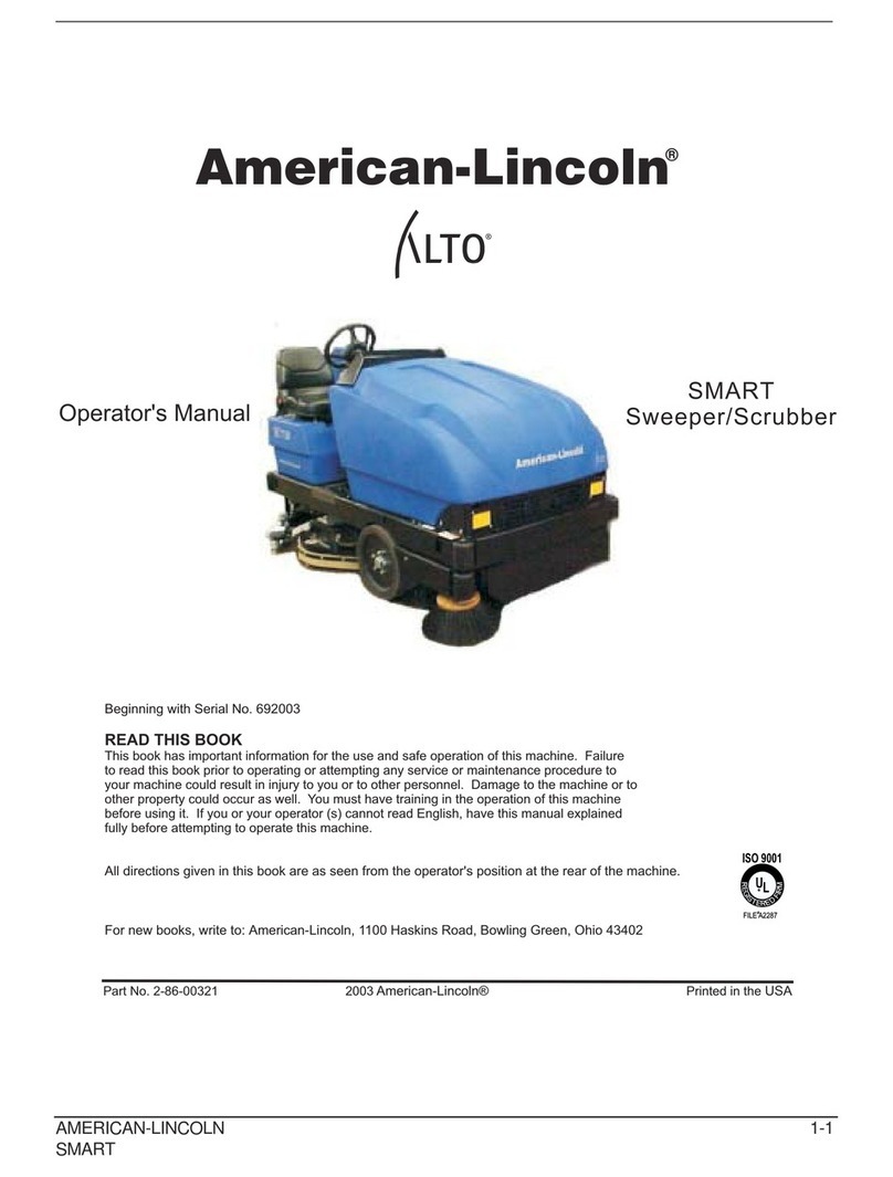
This manual will help you get the most from yourAmerican-Lincoln sweeper / scrubber. Read it thoroughly before operating the machine.
PARTSAND SERVICE
Repairs, when required, should be performed by yourAuthorizedAmerican-Lincoln™Service Center, who employs factory trained service
personnel, and maintains an inventory ofAmerican-Lincoln™original replacement parts and accessories.
Call theAMERICAN-LINCOLN INDUSTRIAL DEALER named below for repairs or service. Please specify the Model and Serial Number when
discussing your machine.
(Dealer, affix service sticker here.)
NAMEPLATE
The Model Number and Serial Number of your machine are shown on the Nameplate, located on the wall of the operator’s compartment. This
information is needed when ordering repair parts for the machine. Use the space below to note the Model Number and Serial Number of your
machine for future reference.
MODEL _______________________________________________
SERIALNUMBER_______________________________________
Note: Reference the separately supplied engine manufacture’s maintenance and operator manual for more detailed engine specification and
service data.
UNPACKING THE MACHINE
Upon delivery, carefully inspect the shipping crate and the machine for damage. If damage is evident, save all parts of the shipping crate so that
they can be inspected by the trucking company that delivered the machine. Contact the trucking company immediately to file a freight damage
claim.
A-4 / ENGLISH
A-4 - FORM NO. - 56041713 - 7765

MACHINE OPERATION
FIGURE 1
YOUR 7765 MACHINE HAS BEEN SHIPPED COMPLETE, BUT DO NOT ATTEMPT TO OPERATE WITHOUT FOLLOWING THESE
INSTRUCTIONS.
PREPARING THE MACHINE FOR OPERATION
1. Connect and tighten battery cables.
2. Fill the tank with REGULAR GRADE unleaded gasoline; Diesel fuel if equipped with diesel engine.
WARNING
Never fill tank while engine is running.Always be sure fuel container and sweeper are
electrically connected before pouring fuel. This can easily be done by permanently attaching one end of an insulated wire to the
container with battery clip on the opposite end.
3. Check engine crankcase oil level.Although properly lubricated at factory, check before starting engine. No special brand oil is used.
Recommended number of operating hours before the initial oil change is the same as normal. See Maintenance.
4. Check radiator coolant level. Permanent type antifreeze is added at the factory to provide protection to approximately -35° F (37° C). To
retain this protection level, always mix 1 part water to 1 part antifreeze.
5. Check oil level in the hydraulic reservoir located at center of machine beside the engine. Oil fill level should be two (2) inches (5 cm.) below
filler neck assembly. If oil is required, add HYDRAULIC FLUID ONLY, automatic transmission fluid FORD type “F”.After the first 50 operating
hours, service must be performed on your engine to insure future high performance and trouble-free operation. See Maintenance.
ENGLISH /A-5
FORM NO. - 56041713 - 7765 - A-5

CAUTIONSAND WARNINGS
SYMBOLS
American-Lincoln™uses the symbols below to signal potentially dangerous conditions.Always read this information carefully and take
the necessary steps to protect personnel and property.
DANGER!
Is used to warn of immediate hazards that will cause severe personal injury or death.
WARNING!
Is used to call attention to a situation that could cause severe personal injury.
CAUTION!
Is used to call attention to a situation that could cause minor personal injury or damage to the machine or other property.
Read all instructions before using.
GENERAL SAFETY INSTRUCTIONS
Specific Cautions and Warnings are included to warn you of potential danger of machine damage or bodily harm.
DANGER!
•This machine emits exhaust gases (carbon monoxide) that can cause serious injury or death, always provide adequate
ventilation when using machine.
WARNING!
•This machine shall be used only by properly trained and authorized persons.
•While on ramps or inclines, avoid sudden stops when loaded. Avoid abrupt sharp turns. Use low speed down hills. Clean only while
ascending (driving up) the ramp.
•To avoid hydraulic oil injection or injury always wear appropriate clothing and eye protection when working with or near hydraulic system.
•Turn the key switch off (O) and disconnect the batteries before servicing electrical components.
•Never work under a machine without safety blocks or stands to support the machine.
•Do not dispense flammable cleaning agents, operate the machine on or near these agents, or operate in areas where flammable liquids exist.
•Do not clean this machine with a pressure washer.
CAUTION!
•This machine is not approved for use on public paths or roads.
•This machine is not suitable for picking up hazardous dust.
•Use care when using scarifier discs and grinding stones. American-Lincoln™will not be held responsible for any damage to floor surfaces
caused by scarifiers or grinding stones.
•When operating this machine, ensure that third parties, particularly children, are not endangered.
•Before performing any service function, carefully read all instructions pertaining to that function.
•Do not leave the machine unattended without first turning the key switch off (O), removing the key and applying the parking brake.
•Turn the key switch off (O) before changing the brushes, and before opening any access panels.
•Take precautions to prevent hair, jewelry, or loose clothing from becoming caught in moving parts.
•Use caution when moving this machine in below freezing temperature conditions.Any water in the solution or recovery tanks or in the hose
lines could freeze.
•Before use, all doors and hoods should be properly latched.
SAVE THESE INSTRUCTIONS
A-6 / ENGLISH
A-6 - FORM NO. - 56041713 - 7765

CONSIGNES DE PRUDENCE ET DE SECURITE
SYMBOLES
American-Lincoln™utilise les symboles reproduits ci-dessous pour attirer l’attention de l’opérateur sur des situations potentiellement dangereuses.
Il est donc conseillé de lire attentivement ces indications et de prendre les mesures adéquates en vue de protéger le personnel et le matériel.
DANGER !
Ce symbole est utilisé pour mettre l’opérateur en garde contre les risques immédiats pouvant provoquer des dommages corporels graves, voire
entraîner la mort.
ATTENTION !
Ce symbole est utilisé pour attirer l’attention sur une situation susceptible d’entraîner des dommages corporels graves.
PRUDENCE !
Ce symbole est utilisé pour attirer l’attention de l’opérateur sur une situation qui pourrait entraîner des dommages corporels minimes ou des
dommages à la machine ou à d’autres équipements.
Lire toutes les instructions avant d’utiliser l’appareil.
CONSIGNES GENERALES DE SECURITE
Les consignes spécifiques de prudence et de sécurité mentionnées ici ont pour but de vous informer de la survenance de tout risque de
dommages matériels ou corporels.
DANGER !
•Les gaz d’échappement (monoxyde de carbone) évacués par la machine peuvent entraîner de graves dommages corporels, voire la mort.
Veillez donc toujours à bénéficier d’une ventilation suffisante lorsque vous utilisez la machine.
ATTENTION !
•Cette machine ne pourra être utilisée que par du personnel parfaitement entraîné et dûment autorisé.
•Evitez les arrêts subits lorsque la machine est chargée et se trouve sur des rampes ou des plans inclinés. Evitez les virages serrés.Adoptez une
vitesse réduite lorsque la machine est en descente. Ne nettoyez que lorsque la machine monte la pente.
•Lorsque vous utilisez le système hydraulique ou travaillez à proximité de celui-ci, veillez à porter une tenue appropriée et des lunettes de protection
afin d’éviter tout risque de blessures ou toute projection d’huile.
•Positionnez la clé de contact sur off (O) et déconnectez les batteries avant de procéder à l’entretien des composants électriques.
•Ne travaillez jamais sous une machine sans y avoir placé, au préalable, des blocs de sécurité ou des étais destinés à soutenir la machine
•Ne déversez pas d’agents nettoyants inflammables, ne faites pas fonctionner la machine à proximité de ces agents ou d’autres liquides
inflammables.
•Ne nettoyez pas cette machine avec un nettoyeur à pression.
PRUDENCE !
•Cette machine n’est pas conçue pour une utilisation sur les chemins ou voies publiques.
•Cette machine n’est pas conçue pour le ramassage des poussières dangereuses.
•Faites extrêmement attention lorsque vous utilisez des disques de scarificateur et des meules.American-Lincoln™ne pourra, en aucun cas, être tenu
pour responsable des dommages occasionnés à vos sols par ce type d’équipement.
•Lors de l’utilisation de cette machine, assurez-vous que des tiers, et notamment des enfants, ne courent pas le moindre risque.
•Avant de procéder à toute opération d’entretien, veuillez lire attentivement toutes les instructions qui s’y rapportent.
•Ne laissez pas la machine sans surveillance sans avoir, au préalable, coupé le contact, enlevé la clé de contact (O) et tiré le frein à main.
•Positionnez la clé de contact sur off (O) avant de remplacer les brosses ou d’ouvrir tout panneau d’accès.
•Prenez toutes les mesures nécessaires pour éviter que les cheveux, les bijoux ou les vêtements amples ne soient entraînés dans les parties mobiles
de la machine.
•Faites attention lorsque vous déplacez cette machine dans un endroit où la température peut descendre sous 0°. Car l’eau contenue dans la
solution, dans les réservoirs de récupération ou dans les conduites risquerait de geler.
•Avant utilisation, toutes les portes et capots doivent être correctement fermés.
CONSERVEZ SOIGNEUSEMENT CES INSTRUCTIONS
ENGLISH /A-7
FORM NO. - 56041713 - 7765 - A-7

OPERATIONS OF CONTROLSAND GAUGES
A Water Temperature Gauge
B Hour Meter
C Fuel Gauge
D Oil Pressure Gauge
E Volt Meter
F Main Broom Switch
G Side Broom Switch
H Dust Control Switch
I Filter Shaker Switch
J Ignition Switch
K Light Switch
L Glow Plug Switch (Diesel Only)
M Side Broom Lift
N Horn Push Button
O Foot Brake
P BackupAlarm Switch
Q Accelerator & Directional Control Pedal
R SeatAdjustment
S Parking Brake
T Check Engine Light (Gasoline/LP)
U Turn Signal
V Throttle Diesel
W Throttle Gasoline/LP
X Solution Control
Y Sweeping Broom Lift Control
Z ESP Option
AA Detergent Flow Knob
AB Detergent Low Light
AC Recycling System Switch
AD Solution High Light
AE Hopper Dump door
AF Hopper Lift
AG Low Solution Warning Light
AH High Recovery Warning Light
AJ Brush Pressure Switch
AK Scrub Brush Lift Switch
AL Squeegee Switch
AM Brush Rotation Switch
AM
AL
AK
AJ
AH
AG
AF
AE
AD
AC
AB
AA
Y
X
U
T
S
F
G
H
I
J
K
L
M
N
O
P
Q
R
A
B
C
D
E
W
V
Z
IGNITION SWITCH
ThekeyedIgnitionSwitch(J)islocatedtotherightofthesteering
column on the front face of the instrument console. It has four
positions.
1. The key turned to the center “OFF” position will shut off
the engine. The following items can be activated in the “OFF”
position.
(a.) Horn
(b.) Light Options
2. The key turned to the right “IGN/ON” position will allow
all the following items to be activated (but will NOT start the
engine):
(c.) Horn
(d.) Light Options
(e.) Turn Signals
(f.) Instrument Panel Gauges
3. The key turned to the far right “START” position will start
the engine. This position is a momentary position.The key will
revert to the “IGN/ON” position when it is released.
LIGHT SWITCH
TheLightSwitch (K) is located above thehornbuttonto the right
of the steering wheel. It will work various light options that are
available for this machine, such as:
* HEAD LIGHTS
* TAIL LIGHTS
* INSTRUMENT LIGHTS
All gauges, with the exception of the hour meter, can have an
optional internal instrument light.
FIGURE 2
A-8 / ENGLISH
A-8 - FORM NO. - 56041713 - 7765

OPERATIONS OF CONTROLSAND GAUGES
4-WAY TURN SIGNAL (OPTION)
The Turn Signal Option (U) is located on the steering column and works as automotive turn signals work, forward on the lever for right and back on
the lever for left. The 4-way flasher will activate when the turn signal lever is pulled out.
GLOW PLUG SWITCH (DIESEL)
Under no circumstances should any other unauthorized starting aids be used at the same time as Glow Plugs. The Glow Plug Switch (L) is located
to the right of the steering column on the front face of the instrument console. Use the following procedure to operate:
1. Before operating the starter motor, press the “GLOW PLUG” button for 20 to 30 seconds.
2. With the “GLOW PLUG” button still depressed, engage the starter motor until the engine starts.
3. Continue to press the “GLOW PLUG” button for a few seconds after the engine has started until even running has been obtained.
4. If the engine does not start, disengage the starter motor, but keep the “GLOW PLUG” button depressed for an additional 10 to 15 seconds.
Keep the Glow Plugs energized while starting the engine and for a few seconds after the engine has been running smoothly.
HORN PUSH BUTTON
The Horn Button (N) is located to the right of the steering column on the front face of instrument console. The horn button is always active. Push
the horn button to sound the horn.
SIDE BROOM LIFT (OPTIONAL FOR MANUAL DUMP)
The Side Broom Lift Lever (M) is located to the right of the instrument console. The handle pulled back and turned to the right will raise the side
broom and lock it into position.
FIGURE 3
ENGLISH /A-9
FORM NO. - 56041713 - 7765 - A-9

OPERATIONS OF CONTROLSAND GAUGES
MAIN BROOM SWITCH
The Main Broom Switch (F) is located on the console to the right of the steering wheel in the SWEEPING section. This switch will activate the Main
Broom. This switch has two positions “ON” and “OFF”. See Sweeping Broom Lift Control.
SIDE BROOM SWITCH (OPTION FOR MANUAL DUMP MACHINES)
The Side Broom Switch (G) is located on the console to the right of the steering wheel in the SWEEPING section. This switch will activate the Side
Broom. This switch has two positions “ON” and “OFF”. See Side Broom Lift Control.
DUST CONTROL SWITCH (WET SWEEP BYPASS OPTION - OPTION FOR MANUAL DUMP
MACHINE)
The Dust Control Switch (H) is located on the console to the right of the steering wheel in the SWEEPING section. This switch will activate the dust
control system.
FILTER SHAKER SWITCH (VARIABLE DUMP MACHINES ONLY)
The Filter Shaker Switch (I) is located on the console to the right of the steering wheel in the SWEEPING section.
NOTE - (Variable Dump Machines Only)
THE MAIN BROOM SWITCH MUSTALWAYS BE PLACED IN THE OFF POSITION BEFORE SHAKING THE FILTER. FAILURE TO DO SO
WILL RESULT IN DUST REMAINING ON THE SURFACE OF THE FILTER ENVELOPES INSTEAD OF DROPPING INTO THE HOPPER.
The button can be used when the ignition key is in the “ignition” position. The filter shaker control button is used during the sweeping cycle and the
hopper unloading cycle. Use the filter shaker control switch to remove dust from the filter. Use the following procedures to operate the filter shaker
control switch:
1. After the machine has made a long sweeping run, turn the broom switch to the “OFF” position.
2. Push the filter shaker control switch for 5 to 15 seconds to allow the filter to unload.
3. Turn the broom switch to the “ON” position. Repeat this procedure after each long sweeping run.
NOTE - (Variable Dump Machines Only)
The main broom, side broom, dust control and filter shaker turn off automatically when the hopper is dumping and/or the dump door is
in a closed position. SEE HOPPER LIFT and HOPPER DUMP DOOR.
FG
I
H
FIGURE 4
A-10 / ENGLISH
A-10 - FORM NO. - 56041713 - 7765

OPERATIONS OF CONTROLSAND GAUGES
WATER TEMPERATURE GAUGE
The Water Temperature Gauge (A) is located on the console panel above the steering wheel in the gauge cluster. The gauge is mechanical and
activated by a sender in the engine. It displays the engine coolant temperature in Fahrenheit.
HOUR METER
The Hour Meter (B) is located on the console panel above the steering wheel in the gauge cluster.This meter is activated when the engine begins
running. The meter indicates actual “run” time of the machine.The meter can used to determine machine maintenance intervals.
FUEL GAUGE
The Fuel Gauge (C) is located on the console panel above the steering wheel in the gauge cluster.This gauge indicates the level of fuel contained
in the fuel tank.
OIL PRESSURE GAUGE
The Oil Pressure Gauge (D) is located on the console panel above the steering wheel in the gauge cluster.The gauge is mechanical and activated
by a sender in the engine. It displays the engine oil pressure in PSI.
VOLT METER
The Volt Meter (E) is located on the console panel above the steering wheel in the gauge cluster. The gauge indicates the charge level of the
battery.
BD
CE
A
WATER
TEMP
100
170
°F 195 220
280
77 91104
138
°C
0
1/4 1/2
FUEL BATTERY
10
12 14
16
-+
HOURS
00
001
1/10
PSI
0
20 40 60
80
278
553
kPa
OIL
PRESS
FIGURE 5
ENGLISH /A-11
FORM NO. - 56041713 - 7765 - A-11

OPERATIONS OF CONTROLSAND GAUGES
SCRUB BRUSHES SWITCH
TheBrushes Switch(AK) is located on the console to the left of the steering wheel in the “SCRUBBING”section. This switch in the position marked
“LOWER” will lower the scrub brush deck and activate the three scrub brushes. The Brush Rotation Switch (AM) and the Brush Pressure Switch
(AJ) can not be activated unless this switch is in the “LOWER” position. This switch in the “RAISE” position will stop the brushes from rotating and
raise the scrub brush deck.
BRUSH ROTATION SWITCH
The Brush Rotation Switch (AM) is located on the console to the left of the steering wheel in the “SCRUBBING” section. This switch reverses the
rotationof thescrubbrushes. Thisswitch hastwopositions,“NORMAL”and“REVERSED”. Thisswitchcannotbeactivatedunless theScrubBrush
Lift Switch is in the “LOWER” position. The switch will light when activated.
BRUSH PRESSURE SWITCH
TheBrushPressureSwitch(AJ)islocatedontheconsoletotheleftofthesteeringwheelinthe“SCRUBBING”section.Thisswitchappliesadditional
downwardpressuretothe scrub brushes.Thisswitchhastwopositions,“NORMAL”and “HEAVY”.ThisswitchcannotbeactivatedunlesstheScrub
Brush Lift Switch is in the “LOWER” position. The switch will light when the switch can be activated.
SQUEEGEE BLADE SWITCH
The Squeegee Blade Switch (AL) is located on the console to the left of the steering wheel in the “SCRUBBING” section. This switch in the position
marked “LOWER” will lower the squeegee and activate the squeegee vacuum. This switch in the “RAISE” position will stop the squeegee vacuum
and raise the squeegee.Aswitch activated by the forward-reverse foot pedal will automatically raise the squeegee if it is in the lowered position and
the machine is in reverse.
HIGH RECOVERY WARNING LIGHT
The High Recovery Warning Light (AH) is located on the console to the left of the steering wheel beside the “SCRUBBING” section. The recovery
warning light will illuminate approximately 5 minutes before the recovery tank is full, giving ample time to complete the scrubbing cycle before the
mechanical float shuts off the vacuum to the recovery tank.
LOW SOLUTION WARNING LIGHT
The Low Solution Warning Light (AG) is located on the console to the left of the steering wheel beside the “SCRUBBING” section. The Solution
Warning Light will illuminate when the solution tank is empty, marking the end of the scrubbing cycle.
AH
AG
AL
AM
AK
AJ
FIGURE 6
A-12 / ENGLISH
A-12 - FORM NO. - 56041713 - 7765

OPERATIONS OF CONTROLSAND GAUGES
HOPPER LIFT - (VARIABLE MACHINES ONLY)
The Hopper Lift Lever (AF) is located to the left of the steering wheel on the left side of the driver compartment. This lever, which is marked
“HOPPER”, raises and lowers the debris hopper to ease unloading.
WARNING
The hopper may drop unexpectedly and cause injury, always engage the safety arm before working under the hopper.
HOPPER SAFETY LOCKARM (VARIABLE DUMP ONLY)
WARNING
When the hopper is raised the safety arm must be engaged before any work is done under the hopper
The Hopper Safety LockArm is located under the hopper assembly.After the work is complete, the safety arm must be disengaged.
HOPPER DUMP DOOR - (VARIABLE DUMP MACHINES ONLY)
TheHopper Dump Door Lever (AE) is located to theleft of the steering wheelon the leftof the driver compartment. This leveropens and closes the
hopper door. This lever is located below the Hopper Lift Door and is marked “DUMP DOOR”.
MANUAL DUMP HOPPER - (MANUAL DUMP HOPPER ONLY)
The Manual Dump Hopper Lever is located under the front bumper. To dump debris, pull the manual dump lever all the way to the position marked
open. Leave the handle in the dump position and back the machine off the pile of debris. When clear of the debris, pull the manual dump lever to
the position marked closed.
SOLUTION CONTROL
To apply solution to the scrubbing brushes, push the Solution Control Lever (X) forward until the desired setting is reached. The solution rate is
continuously variable from off to approximately 1-3/4 GPM at low and 3-1/2 GPM at high. To stop application of solution, pull back on the lever until
it stops at the “off” position.The solution warning light will illuminate when the solution tank is empty, marking the end of the scrubbing cycle.
NOTE
For best results, discontinue application of solution 10 feet
before stopping or making a 90° or 180° turn.
SWEEPING BROOM LIFT CONTROL
The Main Broom Lift Control (Y) is located to the left of the driver
seat. To lower the main broom, grasp the lever and pull back to
clear the locking notch. Move the lever forward tothe first or second
notch in the elongated slot. The first notch, “SWEEP”, is for normal
sweeping (2 to 3 inch [5 to 8 cm.] broom pattern). The second
notch, “FLOAT”, is for heavy sweeping (4 to 5 inch [10 to 13 cm.]
broom pattern).
Toraisethemainbroom,pulltheleverbackandslideintothelocking
notch. You may operate the main broom in either the “SWEEP” or
“FLOAT” position. However, the “SWEEP” position should be used
for normal sweeping and will result in increased broom life. The
“FLOAT” position should be used only when sweeping extremely
uneven areas.
NOTE - (Variable Dump Machines Only)
Aswitch triggered by the hopper and dump door position
controls the sweeping functions, main broom, side broom,
dust control, and filter shaker. The hopper must be down and
the dump door open before these functions will work.
FIGURE 7
AF
AE X
Y
ENGLISH /A-13
FORM NO. - 56041713 - 7765 - A-13

OPERATIONS OF CONTROLSAND GAUGES
THROTTLE CONTROL
See Figure 2. TheThrottle Control (V or W) is located on the left side console. Gas and LP equipment have a Throttle Switch (W). Diesel
versions have a Lever (V). To operate the diesel: For full throttle, grasp the lever and push up and right to the locking notch. To reduce to idle,
grasp the lever and push it up and to the left (away from the locking notch). Let the lever lower until it rests at the bottom of the slot. “Load”
(brooms and/or brushes and/or dust control operating) and “No Load” (brooms, brushes & dust control off) RPMs are the same for gas and
LP equipment. There will be a slight drop between “Load” and “No Load” RPMs with diesels. Always return the throttle switch/lever to the idle
position before turning off the key to stop the engine.
MACHINE RPM’s
IDLE “NO LOAD”
SWEEPER / SCRUBBER
(1 speed) Gas/LP 950 2050
Diesel 950 2150
SWEEPER
(2 speed levels)
Gas/LP 1st 950 2050
2nd 950 2450
Diesel 1st 950 2150
2nd 950 2550
CHECK ENGINE LIGHT (MIL) - GAS, LP ONLY
The Check Engine Light “MIL” (T) is located on the left side console. If the light comes on, it indicates a problem with the engine. Go to the GM
Engine Service Manual, Section 7, for directions on how to diagnose the problem.
PARKING BRAKE
The Parking Brake Lever (S) is located in the left side of the driver compartment floor. See Figure 8. This lever, when raised to the upright position
(a), will “lock” the foot brake pedal in the down position.
FOOT BRAKE
SeeFigure 2. The FootBrake Pedal (O) is locatedto the rightof the steeringcolumn on thefloor of thedriver compartment. See Figure9. The foot
brake on the front wheels is a mechanical system actuated by the brake pedal.
FIGURE 8 FIGURE 9
a
S
A-14 / ENGLISH
A-14 - FORM NO. - 56041713 - 7765

OPERATIONS OF CONTROLSAND GAUGES
ACCELERATOR & DIRECTIONAL CONTROL PEDAL
See Figure 2. The Accelerator and Directional Control Pedal (Q) is located on the floor of the driver compartment, to the right of the brake pedal.
The accelerator and directional control pedal controls machine direction and travel speed.
1. Put foot pressure on the upper portion of the pedal (b). The machine will move forward.
2. Increase the foot pressure on the upper portion of the pedal to increase the forward speed.
3. Put foot pressure on the lower portion of the pedal (c). The machine will move in reverse.
4. Increase the foot pressure on the lower portion of the pedal to increase the reverse speed.
5. To stop the machine, put light foot pressure on the opposite end of the accelerator and directional control pedal. If the machine is moving
forward put light foot pressure on the lower portion of the pedal. If the machine is moving in reverse put light foot pressure on the upper
portion of the pedal.
BACKUPALARM SWITCH
See Figure 2. The Backup Alarm Switch (P) is located under the lower section of the accelerator and directional control pedal and operates the
backup alarm. The alarm makes a loud audible noise when the machine is being driven in reverse.
SEATADJUSTMENT
See Figure 2. The SeatAdjustment Lever (R) is located on the right of the seat. This lever allows the seat to be adjusted forward or back when the
lever is moved.
b
c
FIGURE 10
ENGLISH /A-15
FORM NO. - 56041713 - 7765 - A-15

SCRUBBING SYSTEM OPERATING INSTRUCTIONS
THE ESP RECYCLING CONTROL PANEL
LOW
DETERGENT
ON
OFF
HIGH
SOLUTION
RECYCLING
SYSTEM DETERGENT FLOW
OFF MAX
D
B
C
A
FIGURE 11
THE ESP RECYCLING SYSTEM ON/OFF SWITCH
See Figure 11. The ESP Recycling System ON/OFF Switch (A) turns the ESP recycling system on and off.
SOLUTION HIGH WARNING LIGHT
The Solution High Warning Light (B) will come on if the solution tank is too full of water from the recycling system.
DETERGENT LOW WARNING LIGHT
The Detergent Low Warning Light (C) will illuminate when the detergent tank is low, warning the operator to add detergent.
DETERGENT FLOW KNOB
TherotaryDetergentFlowKnob(D) controlsthedetergentflowintothescrubbingsolution. Theoperatormaychoosefromanydetergentsetting,for
light to heavy cleaning applications. The detergent light will illuminate when the detergent tank is low, warning the operator to add detergent.
A-16 / ENGLISH
A-16 - FORM NO. - 56041713 - 7765

SCRUBBING SYSTEM OPERATING INSTRUCTIONS
THE SCRUBBING SYSTEM - HOW IT WORKS
There are two scrubbing systems available for the 7765 machine, the non-recycling or
standard scrubbing system and the recycling or ESP scrubbing system.
THE NON-RECYCLING OR STANDARD SCRUBBING
SYSTEM - HOW IT WORKS
During the scrubbing process (shown in Figure 13), detergent solution water from the
solution tank is fed to the solution line. There it is fed to the floor where three disc
scrubbing brushes work to dislodge soil.
After scrubbing, the dirty solution is vacuumed from the floor and discharged into the
containment chamber in the forward portion of the recovery tank, where a system of
baffles helps to clarify the solution. Sensors in each tank will indicate by lights on the
control panel when the water in the solution tank is too low or when the water in the
recovery tank is too high.
AB
C
A
D
B
FIGURE 13 FIGURE 14
A Recovery Tank
B Solution Tank
C Baffle
D Detergent Tank
E Check Valve
F Solution Pump
G Orifice
H Filter
I Flow Valve
J Autofil Valve
K Detergent Pump
L Scrub Brushes
M Fill Coupling
N Squeegee
O Floor Contact
P Solution Line
Q Vacuum
BA
H
I
G
J
E
LN
M
O
H
F
K
D
P
B
A
C
Q
NON-RECYCLING RECYCLING
FIGURE 12
ENGLISH /A-17
FORM NO. - 56041713 - 7765 - A-17

SCRUBBING SYSTEM OPERATING INSTRUCTIONS
THE RECOVERY OR ESP SCRUBBING SYSTEM - HOW IT WORKS
During the scrubbing process (shown in Figure 15), filtered water from the solution tank is fed to the solution line, where it combines with detergent
from the metering pump. This mixture is then fed to the floor where three disc scrubbing brushes work to dislodge soil.
After scrubbing, the dirty solution is vacuumed from the floor and discharged into the containment chamber in the forward portion of the recovery
tank,where a systemof baffles helps to clarifythe solution onits way tothe pumping chamber in therear of therecovery tank.At intervals, a system
of sensors activates the recycling pump, which sends filtered solution from the pumping chamber on its way to the solution tank. Here, it is ready to
be mixed with fresh, metered detergent and repeat the cycle.
A Recovery Tank
B Solution Tank
C Baffle
D Detergent Tank
E Check Valve
F Solution Pump
G Orifice
H Filter
I Flow Valve
J Autofil Valve
K Detergent Pump
L Scrub Brushes
M Fill Coupling
N Squeegee
O Floor Contact
P Solution Line
Q Vacuum
BA
H
I
G
J
E
LN
M
O
H
F
K
D
FIGURE 15
A-18 / ENGLISH
A-18 - FORM NO. - 56041713 - 7765

DUST CONTROL OPERATING INSTRUCTIONS
THE VARIABLE DUMP SWEEPINGAND DUST CONTROL SYSTEMS - HOW THEY WORK
Variable Dump 7765 machines are equipped with a sweeping and dust control system. Figure 16 shows the highest position for the variable
dump.
AE Hopper Door Lever
AF Hopper Lift Lever
FIGURE 17
The debris from sweeping is thrown into the hopper (Figure 17). The baffle system that is built into the variable dump debris hopper is designed to
minimize dust in the air while the machine is sweeping. The impeller vacuum fan pulls the lighter dust up and through a baffle system. The Pre-
Clean Flap separates the heavier dust particles to an area below the filters. The dust filters capture the lighter dust particles. This allows the dust
filters to remain cleaner and need less shaking to remove dust. When the dust filters become clogged the filter shaker switch should be pushed to
start the dust shaker cycle. This will extend the life of the filters. NOTE
TURN MAIN BROOM OFF FIRST
AF
AE
FIGURE 16
ENGLISH /A-19
FORM NO. - 56041713 - 7765 - A-19

OPERATING INSTRUCTIONS
FILLING THE SOLUTION TANK
NON-RECYCLING OR STANDARD SCRUBBING SYSTEM
1. Make sure the solution control lever is in the “Off” (rear) position.
2. Open the solution tank cover (right hand side).
3. Fill the tank with 100 gallons (378 L) of water and the correct mixture ofAmerican-Lincoln #100 Industrial Cleaner for the job.
4. Close the solution tank cover.
RECYCLING OR ESP SYSTEM
1. Make sure the solution control lever is in the “Off” (rear) position.
2. Open the solution tank cover (right hand side).
3. Fill the solution tank as outlined above with 100 gallons (378 L) of pure water.
4. Fill the detergent tank with 5 gallons (19 L) ofAmerican-Lincoln #100 Industrial Cleaner.
5. Close the solution tank cover.
NOTE
Fill recovery tank halfway with water for the ESP system
WARNING
To prevent over-sudsing and machine damage,
use onlyAMERICAN-LINCOLN Industrial Cleaning Solution #100.
WARNING
DO NOT put gasoline, combustible or other flammable material
in the solution, recovery or detergent tanks.
NOTE
Before starting the engine, perform the pre-start checklist.
PRE-START CHECKLIST
1. Clean engine air filter element if needed
2. Check engine oil level
3. Check radiator coolant level
4. Check hydraulic fluid level
5. Check fuel level
6. Check all systems for leaks
7. Check brakes and controls for proper operation
BEFORE STARTING ENGINE
1. Set parking brake
2. Make sure all controls are in the “Off” position
TO START ENGINE
1. Be sure accelerator and directional control pedal is in neutral.
2. Turn key to “On” position and hold it until the engine starts.
3. If engine fails to start after following the above procedures, refer to Engine Manual.
WARNING
The manufacturer does not advise storing the machine in below-freezing temperatures unless all fluids have been drained from the
detergent, solution and recovery tanks and associated systems. When machine has been stored in below-freezing temperatures, run
engine at lowest possible settings and let machine sit 5-10 minutes to warm engine and hydraulic oil.
A-20 / ENGLISH
A-20 - FORM NO. - 56041713 - 7765
This manual suits for next models
6
Table of contents
Other American-Lincoln Floor Machine manuals

American-Lincoln
American-Lincoln Encore L25HD User manual

American-Lincoln
American-Lincoln 3366 Installation and operation manual

American-Lincoln
American-Lincoln 3366XP User manual

American-Lincoln
American-Lincoln 6150 User manual

American-Lincoln
American-Lincoln SMART Sweeper/Scrubber 692003 User manual

American-Lincoln
American-Lincoln 4366XP 56516751 User manual

American-Lincoln
American-Lincoln 6150 User manual

American-Lincoln
American-Lincoln MPV 60 User manual