INTRODUCTION
2
1 Introduction and Features
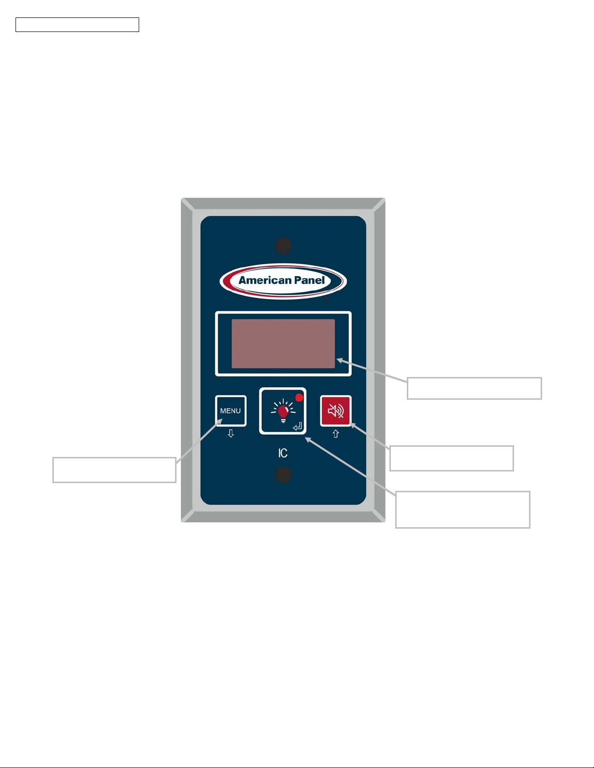
Intelligent Controller IC was designed by American Panel Corporation to control various walk-in door devices
and to monitor the temperature of the walk-in cabinet.
IC features:
Temperature monitoring
High and low temperature alarm with onboard buzzer and alarm time delay
Door frame heater and window heater control
Electronically controlled light switch with light On indicator
Automatic light off
External switch connection for CAL-OSHA back-to-back light control (Optional)
Adaptive setting
1.1 Temperature Monitoring
IC monitors the walk-in cabinet temperature via a probe mounted in the warmest part of the cabinet which is
near the door. The alarm delay will ensure that the alarm does not go off during normal door openings.
For an accurate air temperature reading do not restrict the airflow over the temperature probe. To monitor the air
temperature at a different location an extended temperature probe is available for purchase.
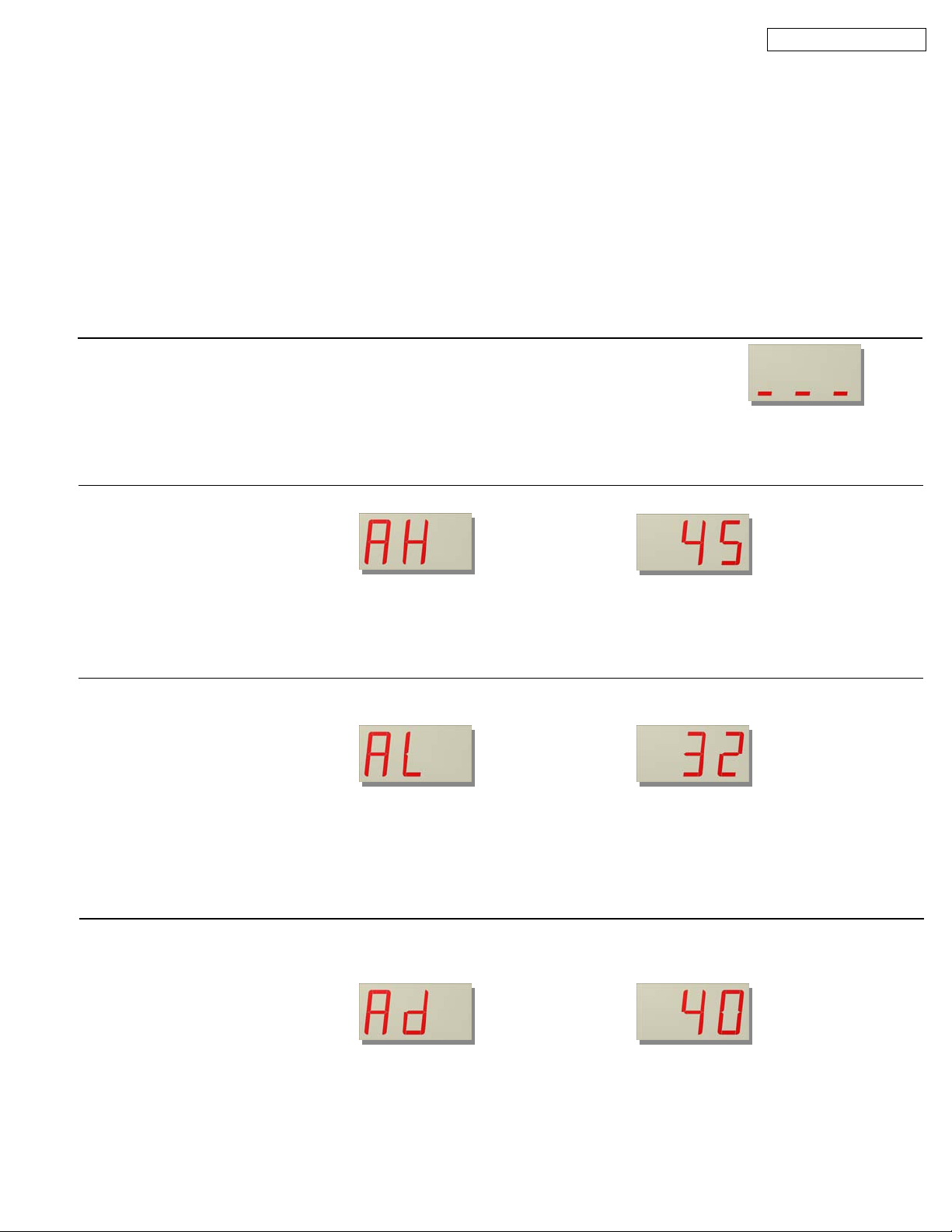
1.2 Temperature Alarms
If the temperature inside the walk-in cabinet goes above the high alarm threshold or below the low alarm
threshold, the temperature reading on the display will blink indicating that the alarm time delay has been
triggered. If the temperature does not return to normal limits within the delay time, the buzzer will go off and
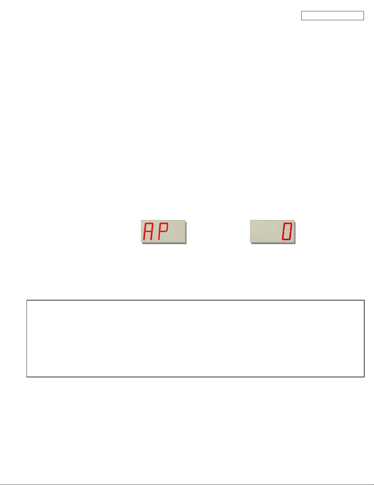
the display will show the alarm message “AH” alternating with the temperature reading. The buzzer can be
silenced by pressing the alarm mute button.
The alarm’s set points and delay times are fully programmable to user’s needs.
Default set points:
High Alarm Trigger Point
(AH) Low Alarm Trigger Point
(AL) Alarm Delay
(AD)
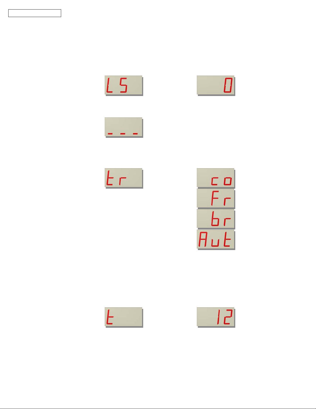
Coole
45oF 32oF40 MinutesFreeze
20oF -25oF
Beer Coole
34oF 30oF
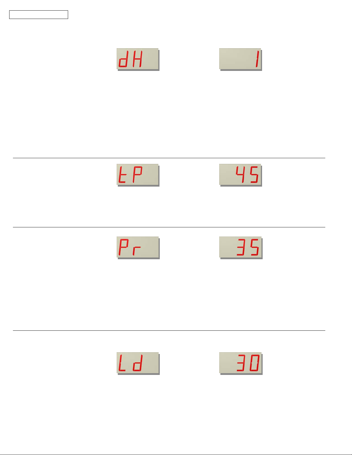
Door Frame Heater and Window Heater Control
IC controller switches on the door frame heater and the window heater (if so equipped) when the air temperature
drops below the preset threshold of 45oF and then cycle them on and off based on a time cycle. On coolers, by
default, the heaters stay on for 35% of a 6-minute cycle and then will stay off for 65%, the cycle will repeat. On
freezers, by default, controller keeps the heaters on until the temperature of the cabinet goes above 45oF. The
alarm’s set points and delay times are fully programmable to user’s needs.
Default set points:
Heaters On (Pr) Heaters Off Heaters switched on below:
(tP)
Coole
35% of a 6-minute c
cle 65% of a 6-minute c
cle 45oFFreeze
100% of a 6-minute c
cle 0% of a 6-minute c
cle
Beer Coole
65% of a 6-minute c
cle 35% of a 6-minute c
cle