American QRP Club NUE-PSK User manual

NUE-PSK Digital Modem
Rev. A19
Modem Connections
1) Power: Either connect two 9V batteries to the clips in the battery compartment (accessible on the underside of the modem), or
connect a standard 2.1mm coaxial power plug to supply a DC power source in the range 10-18 volts (center positive). [If using
batteries, they do indeed fit, connector ends facing center, one at an angle and overlapping the other connector. See Operator’s
Manual for photo.] IMPORTANT: Batteries must be removed when powering the modem from an external supply! (Unless
the “Power Supply Mod” is made to the pc board … see www.amqrp.org/kits/nue-psk31/batt_mod)
2) Radio: Use supplied cable to connect three signals (and ground) to your SSB transceiver. See diagram on next page.
3) Kbd: Connect a standard PC keyboard with PS2-style 6-pin mini-DIN plug to the Kbd connector. A combination PS2/USB-
capable keyboard is also supported when used with the common PS2-USB adapter.
Operation
1) Power On: Turn on the modem using the On/Off switch. The initial splash screen information will display product name, version
number and copyright information. In 2.5 seconds the display will change to show a straight horizontal spectrum baseline with the
frequency cursor. The spectrum display represents 500 Hz on the left to 2500 Hz on the right, with the cursur initially positioned
in the center at 1500 Hz.
2) Tuning: Turn on the SSB transceiver and tune to the digital portion of the desired band – e.g., 7070 kHz or 14,070 kHz. If the
radio cable is wired correctly, and PSK31 signals can be heard on the band, the modem’s spectrum display will show these
signals. The spectrum display indicates relative strength of the audio signals in the band. The digital signals present will have a
distinctive appearance and you can use any of three methods to tune to the signal of interest. You can: (a) adjust the rig’s dial to
place the digital audio spectrum over the modem’s cursor; (b) use the modem’s Tune control to move the cursor to a frequency
where a digital signal is seen; or (c) use the keyboard’s right/left arrow keys to move up/down at low frequency increments, or the
up/down keys to move with bigger steps. When you get close to the digital signal while using the keyboard arrow keys for tuning,
the modem software will recognize the presence of a decodable digital signal and will “snap” precisely to it. When using the Tune
control you can force a “snap” to the closest digital frequency by tapping the Select pushbutton or by pressing the Enter key on
the keyboard.
3) Transmitter Set-up: It is essential to have the modem Tx Audio drive level and your transceiver power level set properly when
using the digital modes. Using a dummy load on the transceiver, set up the rig for normal SSB operation (see your radio’s user
manual), at the normal power level (say 100 watts PEP). Press F8 on the modem keyboard to generate a continuous tone, and
the PTT line should put the rig into transmit. Next adjust the Tx Audio control on the modem to set the transmit level between 15-
14% of the rig’s rated level (15 watts in this example of a 100 watt rig). Press F8 again to discontinue the modem’s Tune mode,
remove the dummy load and connect your antenna. You are now ready to use your modem on the air without overmodulating.
4) “Configure” Menu Selection: Various operating modes and user-configurable settings are available in the Configure menu,
accessed by a pressing and holding the Select pushbutton for one second. The selectable items are then shown individually on
the screen, as controlled by rotating the Tune control. When the desired item is displayed, you can select it by tapping the Select
pushbutton. The Config menu may also be accessed by hitting the keyboard’s F10 key. See the table on page two for all
available configurable items. When you have completed making the desired settings, tap Select when Exit is showing in order to
go back to normal modem use.
5) Typical Operation: As simple usage scenario may be helpful to illustrate initial modem use. After a digital signal is tuned as
described above, and when you are ready to respond to a CQ, press the keyboard’s F12 key to go into Tx mode. The display will
be cleared and characters you enter on the keyboard will be simultaneously echo’d to the display and sent to the rig via audio
tones. When you are finished typing, hit F12 again to toggle back to Rx mode. See the many other macro controls listed on the
next page. Enjoy the QSO!
Page 1

Keyboard Hot Keys
Play Macros: Function Keys F1 to F7
Record Macros: Ctrl-Fn Initiates recording. Enter keystrokes. When finished, Press F9
Erase Macros: Alt-Fn to delete Macro associated with Fn
F8 toggles TUNE mode. May be accessed only in RX or TX. (Not in Setup, or Macro Recording)
F11 displays the first few bytes stored in EEPROM
F12 toggles between RX and TX (again, not in Setup, or Macro Recording)
F10 displays the main Setup Screen. (Accessible only in RX mode). A numeric selection from the Main Menu, selects a submenu,
which is then displayed on the LCD. Another numeric selection activates your selected parameter
Ctrl-K clears the keyboard buffer (in case errors made) before entering callsigns
Ctrl-M saves keyboard entries into a fixed location in EEPROM (for recording your callsign, for use in Macros)
Ctrl-T saves keyboard entries into a RAM location (for recording the other station’s callsign—also for use in Macros)
Alt-M enters a control character into a Macro, that when played back, will insert your callsign
Alt-T does the same as Alt-M, but it forces the entry of the other station’s recorded callsign into the macro playback
Ctrl-F saves the current frequency into EEPROM so that it can be restored at the next power-up
Alt-F retrieves the saved frequency and makes it the current frequency
Ctrl-Tab displays the current frequency (audio) on the character LCD
Ctrl-O toggles display backlight on and off
Parameters Selectable by Hot keys
Ctrl-A Enable AFC
Alt-A Disable AFC
PgUp Increase PGA gain
PgDn Decrease PGA gain
Ctrl-L clears the Character LCD
Ctrl-B clears the internal buffers
Ctrl-Q inserts a TX-OFF control character
in the TX buffer, or Macro
Page 2
Specifications
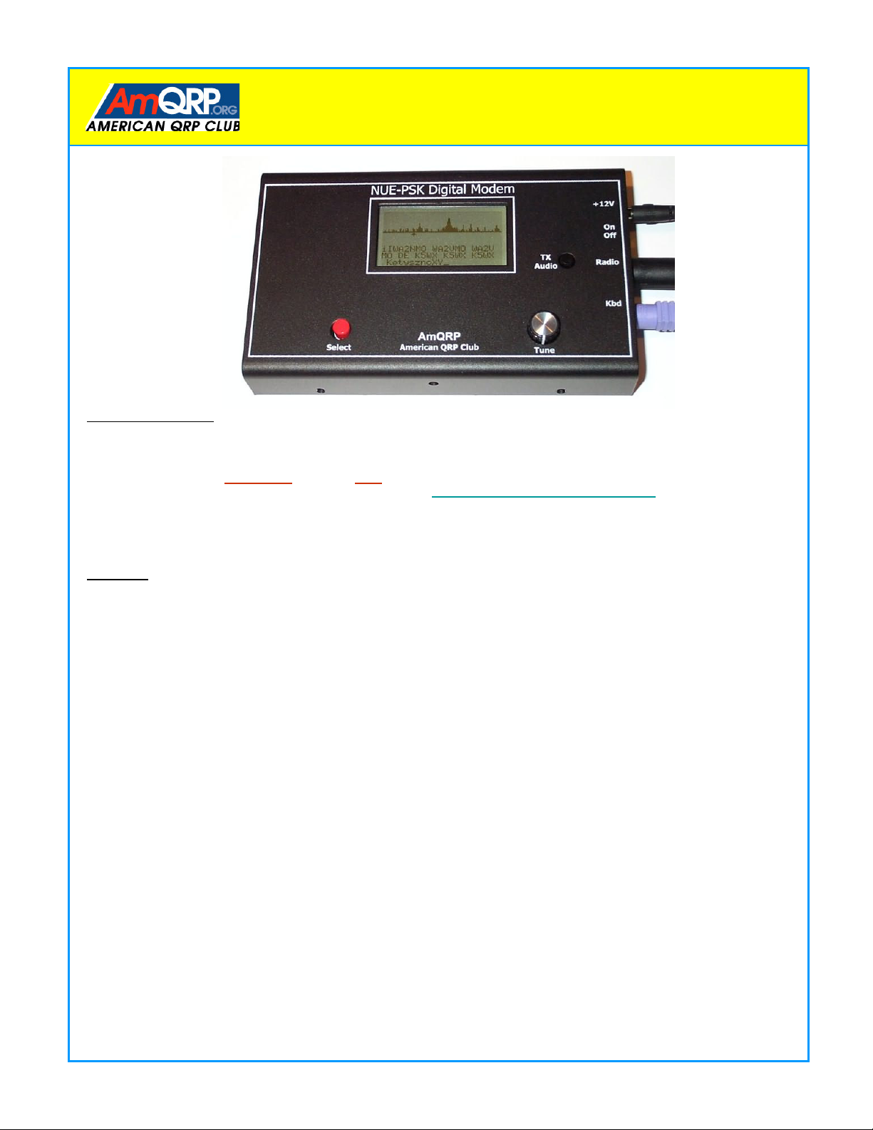
>Standalone, half-duplex modem for digital modes
>Handheld unit ... no PC required
>Menu selects modes, squelch, input audio gain, CW ID, and more
>128x64 pixel graphic LCD displays audio signal spectrum 500 Hz-to-2.5 kHz
(with backlight) and display of TX/Rx typing buffers
> Tune controls modem position along audio spectrum
>Modes currently supported: BPSK31, QPSK, QPSK/R
>External keyboard jack: 6-pin mini-DIN, PS2-compatible, or PS2/USB combo kbd
>Keyboard provides text input for Tx entry, command/mode selection and
modem frequency adjustment
>Connection to SSB transceiver: 8-wire cable (audio in, audio out, PTT)
>Powered internally by two 9V batteries or externally through 2.1mm coaxial jack
>Power requirements: 10-18V DC at 45 ma (typical at 16V supply voltage)
>Field reprogrammability of internal microcontroller to allow for software updating
>GPL open source software - source freely available
>Rugged aluminum enclosure: 6.75" x 4" x 1"
>Single 3.75” x 5.0” pc board
>Lightweight: < 1 pound
> Tx Audio control adjusts for precise audio level to transceiver
Config Menu
Mode: BPSK, QPSK, QPSK/R
Squelch Threshhold: 25, 50
CWID: On, Off
PGA Gain: x1, x5, x16, x32
Tune Increment: Single, Double
Battery Voltage:
TX Audio Level:
Exit
For further information, including a full Operating Manual, visit www.amqrp.org/kits/nue-psk.
An active discussion group is maintained on Yahoo Groups in the NUE-PSK section. Visit http://groups.yahoo.com to get started.
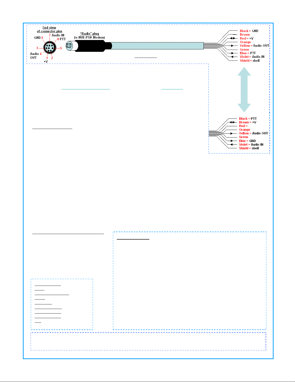
Radio Cable
Connect right end according to recommended data connection for your SSB rig
Radio Cable: Use supplied cable for connection to your SSB transceiver.
Audio OUT: Provides modem tones to the transmitter. Tx Audio control adjusts
transmit audio to an acceptable level for your transceiver. Be careful not to over
modulate. See manual for use of HI-DRIVE shunt to further control Tx drive level.
See http://ne.mara.net/psk31.pdf or other online information at www.arrl.org for
proper setup of transceiver for PSK31 operation. (Search keyword: “PSK31”)
Audio IN: Provides receiver audio to the modem. Ideal signal levels in 10-100 mV
range.
PTT: Provides low level when modem in Tx mode. (The internal FET driver can sink
up to 50ma.)
+V: Can provide power to the modem when modem switch is OFF. It may also
supply power from the modem with modem switch is on.
Two types of cables are provided.
TYPE A is determined by
continuity from connector pin 8
and the blue wire.
TYPE B is determined by
continuity from connector pin 8
and the black wire.
Be sure to use the correct color
coding for your cable
Other manuals for NUE-PSK
2
Table of contents
Other American QRP Club Modem manuals