AmeriFlow Water Systems Inc. ET6500GRO User manual

07\15 RO Manual A
Owners Manual
FOR REVERSE OSMOSIS SYSTEMS
MODEL | ET6500GRO (P/N 10-02-1330GRO)
Includes: Installation and Service Procedures, Specications and Operation Guidelines

107\15 RO Manual
INTRODUCTION
Congratulations, you have purchased one of the highest quality Reverse Osmosis, “RO”
systems available today. This unit combines a series of different ltration processes into one
single module that makes bottle-quality water right in your own home or ofce. This system
has been engineered with only the nest quality components and materials. The system works
connected to most potable city water supplies.
TABLE OF CONTENTS
Introduction 1
Uses and Benets 2
Specication Limitations 2
Warnings 3
Photo of ROs and Contents List 4
Installation Procedures 4
System Position 4
Faucet Installation 4
Figure 1 Diagram 5
Easy Tap Adapter Installation 5
Drain Saddle Clamp Installation 5
Figure 2 Diagram 6
Storage Tank Preparation 6
Tubing Connections 6
System Start-Up Procedures 7
Refrigerator Icemaker Hookup 8
Recommended Filter Service Life 7
Filter Replacement List 8
Filter Change Instructions 9
Recommended Sanitizing Instructions 9
Service and Maintenance Recommendations 9
RO Schematic 10
Replacement Parts List 10
Troubleshooting Guide 11
Performance Data Sheet 13
Manufacturers Warranty 14
Warranty Registration Card 15

07\15 RO Manual 2
SPECIFICATIONS AND LIMITATIONS
I M P O RTA NT: ONLY USE ON POTABLE WATER SUPPLIES Obtain all materials and tools
needed for installation before starting. Please read entire manual carefully before proceed-
ing with installation. Failure to follow manual’s guidelines could cause personal injury or
property damage. Be sure to check household plumbing for signs of leaks, corrosion and
aging. Correct these problems before attempting to install your new RO system.
MANY USES AND BENEFITS OF REVERSE OSMOSIS WATER
1. Quality Drinking Water.
2. Quality Ice Cubes.
3. Car Batteries and Window Washer.
4. Removing some carpet stains.
5. Drinking water for pets.
6. Watering plants.
7. Some humidiers.
8. Washing windows.
9. Making coffee, juice and teas.
10. Use for cooking.
11. Rinsing vegetables.
12. Brushing teeth.
13. Rinsing hair after washing.
14. Steam irons.
15. Ofce coolers.
16. Bottled Water.
CONTENTS OF PACKAGE
1. Filter Pac/RO module
2. Storage Tank
3. Owner’s Manual
4. Warranty Registration Card
5. Standard air-gap faucet or optional col-
ored faucet
6. Parts Bag:
• Easy Tap Adapter w/washer (plastic)
• Drain Clamp (black plastic)
• ¼” Coupler (plastic) for use w/air gap
faucet
• Faucet Adapter plastic (7/16” p × 3/8”
push)
• Tank Ball Valve
• Mounting Screws
7. Water quality monitor
TOOLS & MATERIALS RECOMMENDED FOR NORMAL INSTALLATION
1. Adjustable Wrench (2)
2. Phillips Screw Driver
3. 3/8” drill motor with a 3/8” drill bit
4. Teon Tape
5. Safety Glasses
6. (Optional) Faucet Installation - Step 2 |
1-1/4” hole saw appropriate for sink mate-
rial to be drilled
7. (Optional) Refrigerator Icemaker Hook-Up
- Step 8 | 3/8” polyethylene or polypro-
pylene tubing, 3/8”×3/8”×3/8” plastic
compression T-tting
INCOMING WATER SUPPLY:
pH 3 min. to 11 max.
Water Pressure 40 PSI min. to 85 PSI max. 2000 ppm max.
Total Dissolved Solids (TDS) 40° F min. to 110° F max.
Temperature: 40° F min. to 110° F max.
Air and Water Hardness Water Softener recommended over 10 GPG
Iron Content <1 PPM max.

307\15 RO Manual
WARNINGS
1. Only use with potable water supplies (Water must be microbiologically safe).
2. Installation of RO system must comply with state and local laws and regulations.
3. Check for leaks after installation or service as system is reaching standard operating
pressure and temperature. Check for leaks periodically thereafter. A system may be
inadvertently moved or jarred while other items are moved under the sink. If a tting is ac-
cidentally loosened, a leak could result causing damage to your cabinet.
4. Do not let system freeze. Allow system to warm up to room temperature before installing.
It is best to be installed indoors with air temperature between 60° - 85° F.
5. Attach to cold water supply only.
6. A water-softening appliance is recommended if hardness of incoming water supply is over
10 grains of hardness to increase lter life.
7. Never drain RO tank completely without rst turning off the refrigerator icemaker.
8. Air-gap faucet may cause a slight noise at rst but noise should diminish in about a week.
If noise continues, adjusting drain clamp may help reduce noise. Also, install faucet so
air-gap faucet hole will drain into the sink if drain line gets plugged from obstruction in the
drain line.
9. Water containing iron in excess of 1ppm will require some pretreatment. Consult your local
water authority.
10. This reverse osmosis system contains a replaceable component critical to the efciency
of the system. Replacement of the reverse osmosis component should be with one of
identical specications, as dened by the manufacturer, to assure the same efciency and
contaminant reduction performance.
11. Failure to follow recommended service intervals or use of lters and parts other than those
recommended by the manufacturer may void warranty.
12. Drain RO tank completely at least twice a year. If daily use averages less than a gallon per
day, drain every two weeks. (See page 2 for Uses and Benets)
13. We recommend having all porcelain/enamel-coated sinks professionally drilled.
14. Sanitizing most RO systems on a yearly basis is important for reducing bacteria build-up.
SYSTEM:
System Dimensions 16”×15.5”×7”
Storage Tank Dimension 15.5”×11”
Rejection Rate Up to 98% TDS *
Storage Capacity Up to 3.2 Gallons*
Production Capacity Membrane Rating 50 gallons per day *
*NOTE: These specifications are not the certified results and can vary greatly depending on feed water
makeup, i.e. pressure, temperature, TDS, and hardness. Regular maintenance and filter replacement are
necessary forsystem’s performance andlongevity.

07\15 RO Manual 4
PHOTOS OF RO AND CONTENTS LIST
1. Faucet and tubing
2. Drain clamp
3. Easy Tap Adapter
4. Screws
5. Union Coupling
6. R/O tubing
7. Storage tank with ball
valve
8. FilterPac Unit
9. Re-Min module attached
to top of FilterPac
10. Water quality monitor
INSTALLATION PROCEDURES
STEP 1 SYSTEM POSITION
The RO system needs both a water supply and access to a drain. The RO system is designed
to t under most sinks. The kitchen sink is the most common location for the RO install. Re-
move all system components from boxes and determine the location for placement of the Filter
Pac/RO module, tank, and faucet.
If you desire to hang the Filter Pac/RO module, use mounting screws, placing them to align
with holes in the bracket (make sure the cabinet wall is thick enough to support the Filter
Pac/RO module and that the mounting screws will not pierce through the wall). Hang
Filter Pac/RO module to assure sufcient space is allowed. Remove Filter Pac/RO module
from the wall for now and continue with install.
STEP 2 FAUCET INSTALLATION
1. Check for an extra hole in the sink You must drill a 1 ¼” hole for the faucet if the sink
does not have one. Determine Location of Faucet Hole Check underneath sink before
drilling. Make sure there are no obstructions. Drilling a Stainless Steel Sink Drill a 1 ¼”
hole with a hole-saw or hole punch for an air-gap faucet. Smooth out rough edges with a
le if necessary. A Porcelain/ Enamel-Coated Stainless or Cast Iron Sink The manu-
facturer recommends having this type of sink professionally drilled because of possibility of
chipping or cracking. If you are attempting to drill, use extreme caution. Obtain the proper
tools necessary to drill through the sink material. Follow the drill manufacturers instructions
1
2
5
4
6
7
3
8
9
10

507\15 RO Manual
STEP 3 EASY TAP ADAPTER INSTALLATION
Turn off cold water supply to the sink faucet and relieve pressure by opening the cold water
faucet. (Repair any existing plumbing sink leaks before continuing). Follow water supply from
the cold water supply valve, toward the sink faucet, until you reach a coupling nut (may be at
the base of the faucet). Unscrew the coupling nut. Place rubber washer into the plastic easy
tap faucet adapter and screw adapter onto location of coupling nut. Hand-tighten, then tighten
one more complete turn with a wrench. Re-attach the supply line to the adapter with the cou-
pling nut. Leave the cold water off.
CAUTION:
1. When tightening easy tap, make sure the tube to which you are attaching the easy tap is
not twisted. Use two wrenches to hold existing tube while tightening the easy tap adapter.
2. Examine existing cone shaped washer on water supply tube, adjust or replace if damaged
or worn (not included).
3. If self-piercing valve is used instead of easy tap, attach to hard copper tubing only. Do not
over tighten screws (see instructions on piercing valve package, not included).
NOTE: Push-In style ttings are designed for ease of use. Simply push the tubing in until it seats. Give a tug
on it to make sure it is secure. Insert red locking clip between tting and collar. If you need to remove the
tubing, remove the red locking clip, hold the locking ring collar against the tting while pulling out the tubing.
No inserts or nuts are used with the Push-In style ttings.
STEP 4 DRAIN SADDLE CLAMP INSTALLATION
Location of Drain Clamp
SINK WITH DISPOSAL
Select location to place drain saddle clamp. Best choice is the vertical pipe as near the sink as
possible making certain that the drain clamp is above the horizontal garbage disposal waste
pipe. When connecting the black drain tube to drain saddle clamp keep the tube run as straight
FIGURE 1
countertop
faucet stem
B
A
F
slot washer
white spacer
washer
lock washer (optional)
9/16” nut
5/8” nut × 3/8” tube
adapter
for your type of sink. Place an old towel under
the sink to catch any metal lings and to make
clean up easy. After drilling, clean up metal lings
quickly to avoid staining the porcelain.
2. Install Air-gap Faucet Pre-assemble faucet prior
to installing on the sink. Place the white spacer
onto faucet stem at side toward tubing and open
end upward. Slide spacer up the stem leaving
enough room for the thickness of the sink. Place
the washer onto the stem and thread on the 7/16”
nut up to the spacer. Attach the plastic 3/8” faucet
adapter tting to the base of the faucet stem (do
NOT over-tighten). See A in Figure 1 on the right.
3. Guide the (2) tubes and the faucet stem
through the hole on the sink until the faucet rests
on top of the sink. Center the faucet over the hole.
Position the faucet so the air-gap hole and the
faucet lever point toward the sink basin (in case
drain tube plugs causing water to spill out of the
air-gap hole). Insert the slotted washer under the
sink between the white spacer and the base of
the sink. Tighten the 7/16” nut securing the white
spacer tight against the sink. (see B in Figure)
Faucet may require repositioning before nal
tightening. Remove short packing tubing from top
of faucet and insert faucet spout by pushing spout
straight into the hole until it seats.

07\15 RO Manual 6
as possible and that there are no dips, loops, low spots or kinks. (See D in Figure 2 above).
Also, to reduce noise, assure that RO drain line enters the vertical pipe from a direction other
than the direction of entry of the garbage disposal pipe.
SINK WITHOUT DISPOSAL
Best choice is the vertical pipe about 4” above the water level in the trap.
To Install Drill a 3/8” hole through one side of the drainpipe. Align the hole in the drain clamp
with the hole in the drainpipe. Tighten down the drain clamp snuggly so it will not move on
drain pipe.
STEP 5 STORAGE TANK PREPARATION
1. Wrap the threads on top of the tank with 6 3wraps of Teon tape (do not use any type of
pipe compounds).
2. Screw tank ball valve onto the top of the tank (approximately 4 to 5 full turns - do NOT
over-tighten). Check for leaks once RO is pressurized and while tank is lling and again
when tank is full.
3. Tank is pre-charged with air pressure. Tank can be laid on its side if necessary (tank will
hold approximately 2 to 3 gallons of RO water depending on water pressure, tank position-
ing, and tank air pressure).
4. Tank pressure can be increased to improve water ow to the faucet or refrigerator. Air
pressure can only be tested when tank is completely empty of water. Air pressure of 5-PSI
minimum, 12-PSI maximum is recommended. The higher the air pressure the smaller the
volume of water the tank will hold. Pressure of 10-12 PSI may be necessary to feed a line
to the refrigerator. Over pressurizing may ruin the tank.
STEP 6 TUBING CONNECTIONS
I M P O RTA NT: Fitting manufacturer requires ttings to be re-checked after system reaches
full operating pressure and temperature, Re-tighten and secure as necessary.
1. ¼” White Supply Tube on Filter Pac/RO module Connect the supply (white) tube rmly
into the push-in port on the side of the easy tap adapter installed on the cold water supply
line. Optional If self-piercing valve is used, connect to valve using brass nut, tubing sup-
port, and ferrule, (not included).
2. ¼” red Drain Tube on FilterPac RO Module Air-Gap faucet system Use the coupler
from the parts bag to connect the ¼” red drain tube from the faucet to the red tube from
Filter Pac/RO Module. (See C in Figure 2 on page 6). Push rmly so tubes will not pull out
of coupler or leak.
FIGURE 2
NO DIPS
in LINE
Red line connects to RO drain line
Faucet supply from RO system
C
D

707\15 RO Manual
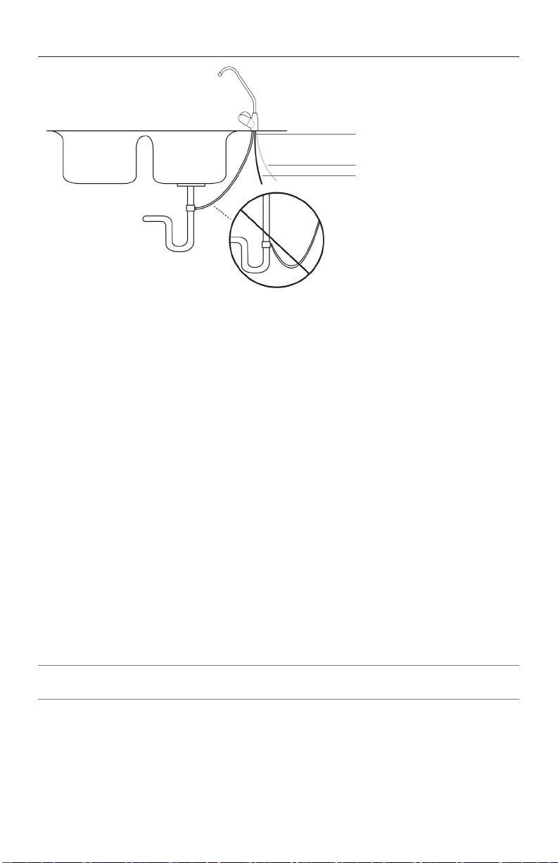
3. 3/8” black Drain Tube from Faucet Connect this tube to the black 3/8” drain clamp. (See
D in Figure 2 on page 6). Tighten rmly so tube will not pull out of drain clamp. IMPOR-
TANT: Do not leave excessive slack in drain tubing. Shorten tubing so that it ows
directly to the drain with no dips, loops, low spots, or kinks.
4. Post Filter Connection to Faucet Depending on the model, connect the 3/8” blue tube
from either the outlet side of the post-lter bowl or the outlet tting from the 10” inline post-
lter cartridge to the 3/8” Push-In adapter tting on the RO faucet.
5. RO Tank Connection Depending on the model, connect the 3/8” blue tube from either the
tee of the inlet side of the post-lter bowl or the tee of the inlet side of the 10” inline post-
lter cartridge to the Push-In ball valve on top of the RO storage tank.
STEP 7 SYSTEM START-UP PROCEDURES
Turn your sink cold water supply valve to the on position while leaving the Filter Pac/RO mod-
ule and RO tank ball valves in the off position (horizontal, which is perpendicular to the valve).
Check for leaks and adjust as necessary.
1. Slowly turn Filter Pac/RO module ball valve to the on position (blue valve vertical, which is
in line with the valve). As water enters the lter bowls and makes its way through the lters
to the membrane element you will hear air escaping through the drain. This is normal.
Open RO faucet on the sink until the water starts coming out. (Water ow will only be a
trickle and may take up to 20 minutes before water starts to come out of the faucet spout
on some units). Shut RO faucet off and check for leaks and adjust as necessary.
2. Open the tank ball valve by turning handle a ¼ turn toward the tubing. Let tank ll for 4 to
6 hours (if you are changing lters, your tank may already be full, so you would not need
to wait). Then turn on RO faucet and drain tank completely, (approx. 5 minutes). Shut RO
faucet off, allow tank to rell, and drain again in 4 to 6 hours. The RO system is shipped
with a food grade preservative and must be ushed out prior to use. DO NOT DRINK THE
RO WATER UNTIL TANK HAS BEEN DRAINED TWICE.
3. Shut RO faucet off and let system ll again. RO water is now ready for use.
I M P O RTA NT: Check carefully for small leaks every few hours for the rst few days to assure
there are no leaks. It is wise on any RO system to inspect for leaks since the system sits
unseen underneath your sink and a small leak may not be detected without close inspection.
Check for leaks occasionally thereafter and make adjustments as necessary.
STEP 8 REFRIGERATOR ICEMAKER HOOK-UP
1. If there is not an ice-line from the RO to the refrigerator, you may choose to run an ice-line
so that your ice and water dispenser will have ltered water. If the distance from the refrig-
erator to the RO is more than 50’, we recommend 3/8” polypropylene or polyethylene tub-
ing for best results. DO NOT USE COPPER. (Be sure you have the recommended water
pressure to your icemaker according to the refrigerator manufacturer’s specications.) 3/8”
tubing, a supplemental storage tank, more RO air pressure, or different usage patterns,
may be required to supply adequate pressure!
2. Connect tube (not included) to appropriate refrigerator connection and to a plastic “T”
tting (not included) spliced into the 3/8” blue tube between the post lter and faucet. It
is recommended to install a ball valve on the tube to the refrigerator for service and start
up purposes. Keep ball valve off until start up procedures are completed and RO tank is
completely full after the second tank draining.
I M P O RTA NT: Never turn on icemaker before RO tank is full of water to avoid damaging re-
frigerator solenoid. If your refrigerator has a water dispenser in the door, upon initial start-up
you will need to depress the water supply lever 2 to 3 minutes before the water will dispense.
STEP 9 RECOMMENDED FILTER SERVICE LIFE
The types of lters listed below vary depending on RO system style. The manufacturer
provides very high capacity carbon lters and replacement intervals are based on our lters.

07\15 RO Manual 8
Other lters may not have the same capacity as original factory lters and may not last as long.
Water conditions vary greatly by region and can affect lter change intervals. For lter change
interval recommendations, follow the guidelines below. If in doubt, contact the manufacturer.
Sediment Pre-lter
These are the only lter(s) that you can visually inspect. They are white when new and will turn
dark with dirt and sediment when changing is necessary. A water softener will extend the life of
the lter(s). Inspect every 6 months or sooner in bad water conditions.
Carbon Pre-lter
These lters should be changed at least once a year. Changing these lters is necessary to
help insure membrane life and water quality. Use of high capacity carbon block lters is rec-
ommended. Granular carbon lters are not recommended because they release excessive
carbon nes at initial start-up, which can reduce the life of the membrane element.
RO Membrane
The RO membrane element is a replaceable component critical for effective reduction of TDS
(Total Dissolved Solids). The RO membrane should be changed when TDS rejection rate falls
below 75%. The rejection rate should be tested periodically to insure optimal performance.
The membrane typically lasts 2-5 years depending on inuent water quality and hardness. See
Performance Indicator information listed below. *
Carbon Post-lter/ Carbon MAP Filter
These lters need to be changed at least every 12 months to insure quality water. Do not wait
until taste is a problem.
*Performance indicator The RO system contains a replaceable treatment component criti-
cal for effective reduction of TDS (Total Dissolved Solids). The product water shall be tested
periodically to verify that the system is performing properly. Testing can be accomplished by
contacting the service company that installed your RO system or an authorized dealer. If a
service company is not available in your area a water sample may be sent to AmeriFlow™ for
a free TDS test of your RO water. Additionally a water quality monitor is available for purchase
from the manufacturer that will allow the product water to be tested at home.
To send water samples for TDS testing to the manufacturer do the following. Using 2 clean
containers put approximately ½ cup of tap water in one container and ½ cup of RO product
water in the other container. Send both samples to the manufacturer along with your contact
information.
To order replacement lters or locate a source in your area call the factory: AmeriFlow™ Water
Systems Inc. 6 02-275 - 4188.
REPLACEMENT FILTERS – PART NUMBERS – REPLACEMENT FREQUENCY
ET6500GRO RO
P1 #13 6 -1110 -1 6 month - 1 year.
CB05 #135 -1210-1 1 year
TFC-50 #138-150GRO 2 - 5 years
CB-A #135 -1210-2 1 year
#135 - 3110 -1 1 year
Re-Min 1 year

907\15 RO Manual
STEP 10 FILTER CHANGE INSTRUCTIONS
1. Sediment and Carbon Turn Filter Pac/RO module ball valve to off position. Turn tank ball
valve off. Turn on RO faucet to help de-pressurize system. Unscrew lter bowls by turning
counter-clockwise. Remove old lters and discard. Clean lter bowls if needed in warm,
soapy water. Insert new lters into appropriate lter bowls. Make sure o-ring at top of lter
bowl is clean, lubricated and seated properly when tightening. If changing the post lter, do
so now following the same procedure as the pre-lters. Follow Step 7 - System Start-Up
Procedures. Check for leaks and adjust as necessary.
2. RO Membrane Turn RO tank and water supply off. Turn on RO faucet to help de-pres-
surize system. Disconnect white tube going into membrane housing. Unscrew end cap of
membrane housing. Have a towel and a bucket handy because some water will pour out.
Pull out old membrane and clean membrane housing if necessary with warm, soapy water.
Insert new membrane in the same direction as old membrane. Push rmly up to properly
seat RO membrane. Replace end cap and reconnect white tube to membrane housing.
Follow Step 7 - System Start Up Procedures. System should be sanitized each time mem-
brane is changed. (See Recommended Sanitizing Procedures on page 9). Test TDS (Total
Dissolved Solids) rejection rates and be sure the rates are over 75%. A TDS monitor is
optional on some models and included on others. If your unit did not come with a monitor,
you can order one or seek advice from a local water treatment service company. A new
membrane should
STEP 11 RECOMMENDED SANITIZING PROCEDURE
The manufacturer recommends having your system professionally sanitized once a year. The
best time to sanitize is when changing all the lters and/or when changing the membrane.
3. Drain all water from RO tank by turning on RO faucet until water stops owing. Follow Filter
Changing Procedures (assuring ball valve on tank and Filter Pac/RO module are in off po-
sition). Remove old pre-lters and membrane from housings. Remove the post-lter. On the
ET5000 a 3/8” union, and on the ET6000 a ¼”×3/8” reducer union, (not included), will be
necessary to reconnect the tubing together without the post-lter installed during sanitizing
procedures.
4. Carefully put 2 capfuls of household bleach into the empty lter bowl canisters. Re-install
lter bowls without lters. CAUTION: Be careful not to splash bleach on hands or surfaces.
5. Turn water supply on (open ball valve on tank and RO module) and let system ll for 4
minutes with tap water. Shut system off. Turn RO faucet on until water comes out and then
shut it off.Let entire system sit for about 30 minutes to sanitize. Then turn on RO faucet and
let system drain until empty. Turn off water supply valves and empty water in lter bowls.
Re-install lter bowls. Turn the water supply on again. Turn off faucet and let system rell
with tap water as before. Drain again. Install new lters following the Filter Change Instruc-
tions - Step 10. Follow System Start-Up Procedures Step - 7.
STEP 12 SERVICE AND MAINTENANCE RECOMMENDATIONS
All Reverse Osmosis systems require periodic maintenance to insure the continuation of water
quality. Test TDS rejection rates at least every 6 months. Changing lters is important for con-
tinuous good water quality. Filters need to be replaced at recommended intervals as old lters
may retain a considerable amount of debris and contaminants. Failure to change lters, use of
lower quality lters, or improper sanitization can dramatically reduce membrane life and water
quality. DO NOT WAIT UNTIL YOUR WATER TASTES BAD TO REPLACE YOUR FILTERS.
REMEMBER: Most contaminants do not have a foul taste except in extreme quantities. Testing
the check valve, ow restrictor, incoming water pressure, water hardness, and TDS levels peri-
odically are important to help extend membrane life and overall water quality. Your local water
professional can easily perform these tests. Failure to follow proper maintenance instructions,
use of lters or parts other than those recommended by the manufacturer, or use of an unau-
thorized service agent may void your warranty.

07\15 RO Manual 10
RO SCHEMATIC
WT= White
BK6= 3/8” Black
BL= B lue
BL6= 3/8” Blue
RD= Red
RO WATER
FAUCET
CARBON FILTER
REMIN
GRO MEMBRANE
WATER
CONSERVATION
SHUT-OFF
BL
BL
BL6
BK6
RD
TO
DRAIN
JG
EASY
TAP
COLD
SEDIMENT
FILTER A . A .C.T. CARBON
FILTER RO WATER
STORAGE
TANK
BL6
BL6
BL6
BL6
BL
WT
WT
WT
REPLACEMENT PARTS LIST
QUANTITY PART NO. DESCRIPTION
1103-38148-JGPL JG Easy Tap
1419-1404-1 ¼” JG 90 Ball Valve
2804-11-04 ¼” Hex Nipple
1419 -1406 3/8” JG 90 Ball Valve, Storage Tank
2 (3)* 805-40-02 Fitting ¼” mpt × ¼” JG Elbow *(ET6000)
1123-541 Water Conservation Shut-Off Valve
1138-150GRO 50 GPD GRO Membrane
1128-R O-ring, Membrane Housing
2805-40-04 Fitting 1/8” mpt × ¼” JG Elbow
1121-1604-1 Check Valve Fitting 1/8” mpt × ¼” JG Elbow
1129-260 Flow Restrictor, 260 ml
1110 - 0 3181 3.2 Gallon Storage Tank
1805-40-042 Fitting 3/8” stem × ¼” JG Elbow
1805-70-06 Fitting Union 3/8” JG Tee
1805-S10-06 Fitting ¼” mpt × 3/8” stem
1805-40-06 Fitting ¼” mpt × 3/8” JG Elbow
1125-124 RO Faucet, Specify Color

11 07\15 RO Manual
REPLACEMENT PARTS LIST
1805-25-04 Faucet Adapter 3/8” × 7/16” fpt
1805-15-04 ¼” Union JG
1124- 462 Drain Saddle Clamp
3127-1101 Filter Bowl Canister
3127-1R O-ring, Filter Bowl canister
6805-LC-06 3/8” Locking Clip JG
11 805-LC-04 ¼” Locking Clip JG
2122-321 Clips, Membrane
2 (4)* 122-24321 Clips, Post Filter
1120-131 Bracket
1114-10 Water Quality Monitor
TROUBLESHOOTING GUIDE
PROBLEM CAUSE SOLUTION
Cloudy ice
cubes or milky
colored water.
Bad membrane. Replace Membrane and sanitize when below 75%
rejection
Water supply. High oxygen content
Refrigerator. Some refrigerators freeze differently, leaving the ice
cube looking cloudy. Let cube dissolve in glass of water.
If just air, will oat to surface and dissipate.
System is still new. This is normal and should clear up in two weeks.
Noisy drain or
faucet.
Air gap faucet. A little noise is common with air gap faucets. Check
manual to be sure installed in proper location. Allow two
weeks for air to work out of system.
Drain tube. Check that drain tube from faucet is continuously down
hill to drain. Loops or dips will cause noise. Disconnect
drain tube and clean free of debris.
Hole on faucet
is leaking.
Drain clamp slipped. Align drain clamp hole with drainpipe hole.
Drain tube loops or
dips
Shorten drain tube from faucet until smooth down hill
ow to drain.
Restriction in drain
tube.
Disconnect drain tube and clean out restriction.
Filter bowl
canister leak.
O-ring not sealed
properly.
If damaged, replace. If dirty, clean, lubricate and re-
tighten lter bowl. Hand tighten rmly.

07\15 RO Manual 12
Water does not
taste or smell
right.
Bad membrane. Replace membrane when below 75% rejection and
sanitize.
Filters have expired. Replace lters. Should be replaced every 6 to 12
months.
Little water use. Drain or use entire tank. Should be done every 2 weeks
if low water use.
System needs sani-
tizing.
Sanitize (see Step 11: Recommended Sanitizing In-
structions) and replace lters.
Little water from
faucet.
Over pressurized
tank.
When empty, tank pressure should be between 5-12
PSI.
Incoming water pres-
sure is below 40 PSI.
Increase pressure to 40 PSI with a pump.
New system or lters
just changed.
System takes 4 to 12 hours to completely ll.
Bad check valve. Replace check valve.
Tank valve not open. Open valve.
Bad storage tank. Replace storage tank. If not bad check that tank air
pressure is between 5-12 PSI when empty.
Filters clogged. Replace lters.
Kinked tube. Un-kink tube. If damaged, replace tube.
System is con-
tinually running.
Shut off valve not
working.
Replace shut off valve.
Low city supply water
pressure.
Increase water pressure to 40 PSI with a pump.
Bad check valve. Replace check valves.
Ice being made in
refrigerator.
Nothing you can do, ice is made on demand.
System is new. Allow 2 weeks for air to bleed.
Ice maker not
working.
Ball valve to ice line
is off.
Turn on ball valve.
Ice maker in refrig-
erator is off.
Turn to on position.
Ice maker line frozen. Thaw with hair dryer. Make sure you have a full tank of
water before turning ice maker on.
Tube to refrigerator is
kinked.
Find kink and repair.
No water out
of refrigerator
door.
1-quart reservoir
not full.
Hold down dispenser handle for approximately 3 min-
utes until water comes out. Make sure R/O tank is full.
Makes water
slowly.
Normal R/O process. Your R/O system makes water a drop at a time. 3-gallon
storage tank should be full in 4-12 hours.
Low city water pres-
sure.
Increase to 40 PSI. with a booster pump.
Kinked tubing. Find kink and repair.
Filters plugged. Replace lters.
Bad membrane. Replace membrane.

13 07\15 RO Manual
PERFORMANCE DATA SHEET
REVERSE OSMOSIS SYSTEM MODEL NUMBERS 1-1310-10, 1-1320-10
REPLACEMENT TREATMENT COMPONENTS SEE STEP 9, PAGE 8
GENERAL INSTALLATION — OPERATION — MAINTENANCE REQUIREMENTS
• Do not use with water that is microbiologically unsafe or of unknown quality without adequate
disinfection before of after the system.
• This reverse osmosis system contains a replaceable treatment component critical for effective
reduction of total dissolved solids. The product water shall be tested periodically to verify that
the system is performing properly.
• While testing was performed under standard laboratory conditions, actual performance may
vary.See Owner’s manual for Manufacturer’s limited warranty.
• This system has been tested and shown to operate at its calculated recovery rating and ef-
ciency rating under standard test conditions.
• Chlorine in the inuent water may affect the R/O membrane polymers.
• See Owner’s manual for complete installation / operation and maintenance requirements, as
well as user responsibility and parts and service availability.
*PERFORMANCE INDICATOR. The product water shall
be tested regularly to verify that the system is perform-
ing properly. Testing can be accomplished by contacting
the service company that installed your RO system or an
authorized dealer. If a service company is not available in
your area a water sample may be sent to AmeriFlow™ for a
free TDS test of your RO water. Additionally a water quality
monitor is available for purchase from the manufacturer
that will allow the product water to be tested at home.
Test parameters: 25°+ 1°C, 45 PSI, and pH of 7.3
*Recovery Rating means the percentage of the inuent water to the membrane portion of the system that
is available to the user as reverse osmosis treated water when the system is operated without a storage
tank or when the storage tank is bypassed. *Efciency Rating means the percentage of the inuent water
to the system that is available to the user as RO treated water under operation conditions that approximate
typical daily usage.
Pentair Membrane 655006-00 RODTP Contaminant Reduction Information for PDS
Daily Production Capacity
Rejection Rate
Storage Capacity
Recovery Rating*
Efciency Rating*
System Weight
System Dimension
Storage Tank Dimension
Min./max. pressure
Min./max. temperature
7.7
93.3%
2.6 gallons
22.4%
11.7%
27 lbs.
16” x 15.5” x 7”
15.5” x 11”
40 – 85 PSI
40° - 110° F

We have any parts you need for
this unit.
We are happy to give you
advice and instruction relating
to the operation of this unit.
Contact us at AZH2O.COM
Table of contents
Other AmeriFlow Water Systems Inc. Water Filtration System manuals
Popular Water Filtration System manuals by other brands

AQUAMAXX
AQUAMAXX HOB-1 installation guide

Duramaxx
Duramaxx 10028064 manual

Brita
Brita AquaAroma Crema operating instructions

Atlantic Ultraviolet
Atlantic Ultraviolet Mighty Pure MP16A owner's manual

BEGA
BEGA 116 Instructions for use

Evoqua
Evoqua Neptune Benson Defender FP Series Installation and operation manual

GE
GE GNUL30B Owner's manual and installation

Ispring
Ispring DF1 Series user manual

stefani
stefani Whole Of House Installation and operation manual

Quincy Compressor
Quincy Compressor EWS 20 Instructions for installation and operation

JRC
JRC NSVS616 manual

OptiPure
OptiPure OP350 Installation, operation & maintenance manual