Worldwide Energy and Manufacturing (Nantong) Co., Limited
2
Do not drop the module or allow objects to fall on the module.
Do not leave the module unsupported or unsecured.
Keep all electrical contacts clean and dry.
4. Product identification
Each Amerisolar module has two identical barcodes with 15 digits for its unique identification
(one is in the laminate, and the second is on the backsheet).
A nameplate is affixed on the backside of the module. This nameplate describes main
characteristics of the module, which include the product type, maximum power, open circuit
voltage, short circuit current, maximum power voltage, maximum power current, all as
measured under standard test conditions; maximum system voltage, weight, dimensions etc..
Do not remove any labels from the module. If the label was moved out, the module will void
the warranty.
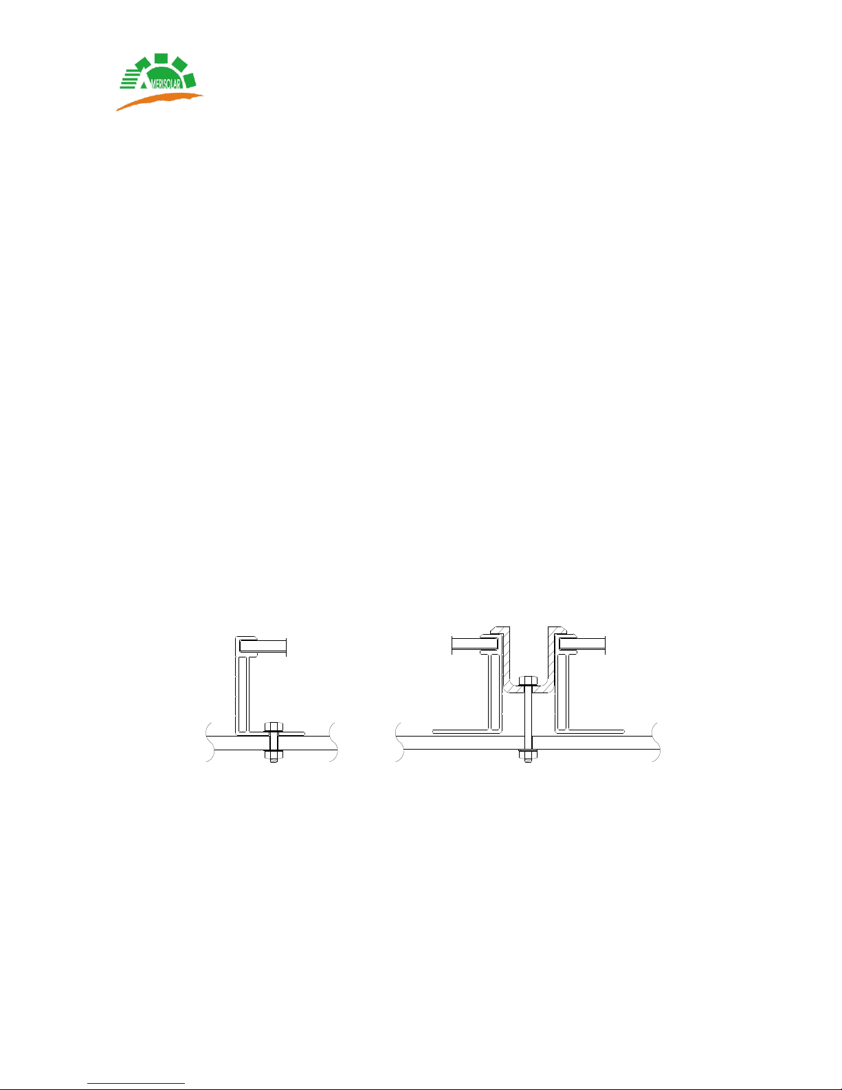
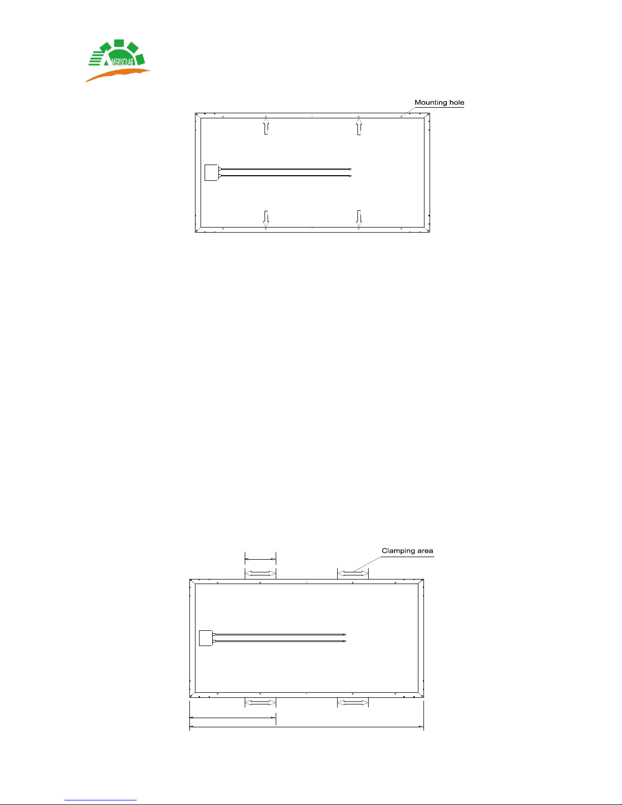
5. Mechanical installation
5.1 Climate condition
Amerisolar modules should be installed in the following conditions:
Ambient temperature: -20°C to +40°C
Operating temperature: -40°C to +85°C
Storage temperature: -40°C to +40°C
Humidity: below 85RH%
Wind load: below 2400Pa
Snow load: below 5400Pa
5.2 Site selection
Amerisolar modules should be installed in a location where they will receive maximum
sunlight throughout the year. In the northern hemisphere, the modules should typically face
south, and in the southern hemisphere, the modules should typically face north.
When choosing a site, avoid trees, buildings or obstructions, which could cast shadows on
the modules especially during the winter months when the arc of the sun is lowest over the
horizon. Shading causes loss of output, even though bypass diodes have been fitted in the
junction box of the module to minimize any such loss.
Amerisolar modules have a Class C fire resistance rating in accordance with IEC61730-2
standard. For roof installation, modules should be mounted over a fire resistant covering, with
adequate ventilation between the module backsheet and the mounting surface. In order to