manuals.online logo
Brands
  1. Home
  2. •
  3. Brands
  4. •
  5. AMES
  6. •
  7. Control Unit
  8. •
  9. AMES 1000SS Series User manual

AMES 1000SS Series User manual

1
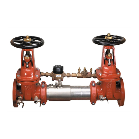
RP/IS-A-1000SS
Detector Check Valve
Assemblies
Sizes: 4" – 10" (100 – 250mm)
• Installation
• Service
• Repair Kits
• Maintenance
A Division of Watts Industries
875 National Drive • Suite #107 • Sacramento, CA 95834 • Phone: 916-928-0123 • Fax: 916-928-9333
www.amesfirewater.com
For other repair kits and service parts, send for
Ames Repair Parts Price List, PL-A-RP-BPD.
For technical assistance, contact your local
Ames representative.
IMPORTANT: Inquire with governing
authorities for local installation requirements.
Its important that this device be tested
periodically in compliance with local codes,
but at least once per year or more as service
conditions warrant. If installed on a fire
sprinkler system, all mechanical checks,
such as alarm checks and backflow
preventers, should be flow tested and
inspected internally in accordance with NFPA
13 and NFPA 25.
Limited Warranty: Ames Company warrants each
product to be free from defects in material and
workmanship under normal usage for a period of one
year from the date of original shipment. In the event of
such defects within the warranty period, the Company
will, at its option, replace or recondition the product
without charge. This shall constitute the sole and
exclusive remedy for breach of warranty, and the
Company shall not be responsible for any incidental,
special or consequential damages, including without
limitation, lost profits or the cost of repairing or
replacing other property which is damaged if this
Series 1000SS
product does not work properly, other costs resulting
from labor charges, delays, vandalism, negligence,
fouling caused by foreign material, damage from
adverse water conditions, chemical, or any other
circumstances over which the Company has no
control. This warranty shall be invalidated by any
abuse, misuse, misapplication or improper installation
of the product. THIS WARRANTY IS IN LIEU OF ALL
OTHER WARRANTIES, EXPRESS OR IMPLIED,
INCLUDING ANY IMPLIED WARRANTIES OF
MERCHANTABILITY OR FITNESS FOR A PARTICULAR
PURPOSE. Any implied warranties that are imposed by
law are limited in duration to one year.
Some States do not allow limitations on how long
an implied warranty lasts, and some States do not
allow the exclusion or limitation of incidental or
consequential damages. Therefore the above
limitations may not apply to you. This Limited
Warranty gives you specific legal rights, and you
may have other rights that vary from State to State.
You should consult applicable state laws to
determine your rights.
1000SS
2
NOTE: Ames assemblies require minimum maintenance. All
assemblies must be retested once maintenance has been
performed. Before servicing be certain shut off valves are closed.
A. The installation and maintenance of any Ames Detector
Check Valve should be performed by a qualified licensed
technician. Failure to do so may result in a malfunctioning
assembly. All instructions should be read thoroughly by the
technician before installation or performing any maintenance
on the assembly.
B. Before installing an Ames Detector Check Valve, flush the
lines thoroughly to remove all debris, chips and other foreign
objects. Failure to do so may make the assembly inoperable.
C. Allow sufficient clearance around the installed assembly to
conduct testing, servicing and inspection. Allow a minimum of
12" from the flood level to the bottom of the assembly.
D. Be sure to contact local code authorities for proper
installations.
INSTALLATION NOTE: The flange gasket bolts for the gate valves
should be retightened during installation as the bolts may have
loosened due to storage and shipping.
ATTENTION INSTALLER: After installation, please leave this
Instruction Sheet for occupant’s information.
Installation Instructions
Removing Cam-Check
Place yourself so that the water flow through the valve is left to right.
1. Shut down water system by closing two gate valves and lock out
system if possible. Slowly open bleed port to relieve internal pressure.
After pressure is relieved, loosen bolts on groove coupler and remove
groove coupler and copper plate from valve body.
2. Unscrew (counter clockwise as viewed through the port facing the
check) the Cam-Check. Insert the two grooved coupler bolts into the
holes in the face of the seat. Be sure that the pins or bolts are
installed with one on each side of the cam bar as shown. Insert a long
screwdriver or pry bar between opposing pins and loosen the check
counter clockwise) until it comes free to turn by hand. Finish unscrew-
ing the Cam-Check by hand using the support ears for the clapper
and cam bar to turn the check. (See fig #1A)
3. Lift the Check straight up and out of the port access hole.
4" and 6" Cam-Check Removal
4" and 6" Cam-Check Installation
Install the Cam-Check
Prior to installing the Cam-Check, ensure that all threads are clean
and free of debris, grit, or other particles. Thoroughly clean O-rings
grooves and lubricate O-rings with an FDA approved lubricant.
1. Insert the Cam-Check through the cover port with the clap-
per facing down. Align the threads of the Cam-Check with
the threads in the body and start to thread the Check in by
hand - using the ears which extend from the seat ring to
turn the check assembly. DO NOT use the clapper or the
cam bar to turn the check assembly.
2. Tighten the Cam-Check. Insert grooved coupler bolts into
the holes in the face of the seat (or use the bolts from the lid
groove coupler). Be sure that the pins or bolts are installed
with one on each side of the cam bar. Insert a long screw
driver or pry bar between opposing pins and tighten the
check (clockwise as viewed through the port facing the
check) until it comes to a solid stop. The back the check
out about 15 degrees or from the 1:00 position to the 12:00
position. (See Fig #1B).
START UP: After re-installation of the cover plate and groove coupler — the downstream shutoff valve should be closed. Open upstream
gate slowly, fill the valve and bleed the air through bleed port. When valve is filled, open the downstream shut off slowly. Failure to bleed air
from assembly may cause water hammer or shock damage to the water system.
Figure #1A
Figure #1B
3
Repair Parts
Ames Part No.
Item # Part Description Qty. 4" 6"
1. Cam-Check Assembly 1 7015580 7016695
2. Cam-Check O-ring (removable) 1 7013229 7013301
3. Groove Coupler 1 7013194 7013287
4. Groove Coupler Gasket 1 7013248 7013308
5. Cover Plate 1 7013241 7013289
#1 Cam-Check
Figure 3
Figure 2
Cam bar
2
3
4" and 6" Cam-Check Disassembly
Please use caution when disassembling cam-check.
Figure 4
Using a thin rod or screwdriver, lift the cambar up so that the
clapper is free to swing upwards away from the seat.
Figure 5
Using your free hand, swing the clapper open until the roller is
almost to the free end of the cambar. Align the maintenance
lockout holes in the cambar and the hinge arms.
Secure the check assembly in the maintenance position by
inserting a rod or thin screwdriver through the lock-out holes.
Figure 6
Remove 1 c-clip from the center pivot pin. Withdraw the
centerpivot pin from the clapper and the hinge arms. Remove
the clapper assembly from the check assembly module.
Note: You may replace this item as an assembly.
Figure 4 Figure 5 Figure 6
Repair Parts
Ames Part No.
Item # Part Description Qty. 4" 6"
1. 1st Cam-Check O-ring (removable) 1 7013229 7013301
2. Clapper Assembly (removable) 1 7016899 7016900
3. Pivot Arm Pin (removable) 2 c-clips 1 7013853 7013841
Figure 7
1
453
21
4
RP/IS-A-1000SS 0310 ©Ames Co. 2002 Printed in U.S.A.
EDP# 7016818
A Division of Watts Industries www.amesfirewater.com
875 National Drive • Suite #107 • Sacramento, CA 95834 • Phone: 916-928-0123 • Fax: 916-928-9333
Ames Part No.
Item # Part Description Qty. 4" 6"
1Knuckle Joint Assembly (Complete Unit) 1 7015552 7015552
2Clapper Plate With Attached Link (not shown) 1 7011413 7011413
3Springs 3 7011323 7011323
43/8" Stainless Steel Bolts 2 7014619 7014619
5Washer (not shown) 2 7014585 7014585
6Bronze Seat (Replaceable in Line) 1 7011163 7011163
7Seat O-Ring 1 A300706 A300706
8Cover Plate 1 7011016 7011016
9Groove Coupler 1 A605530 A605530
10 Clapper Retainer Clip (Diagram 1) 1 7013913 7013913
8" and 10" Knuckle Joint Assembly Removal and Installation
1. Shut down water system and lock out if possible.
2. Loosen vent screw in lid slowly to ensure system pressure
has been relieved.
3. Loosen and remove all inspection port bolts and remove lid
and gasket from valve.
4. Install proper size clapper retainer clip (see diagram 1). Be
sure clip is pushed to within 1⁄2" of linkage.
5. Loosen equally the two knuckle joint mounting bolts, until
assembly is free. As bolts are loosed linkage will release
slightly and lock clapper retainer clip in place.
6. Remove knuckle joint from body assuring clapper retainer
clip is not disturbed, as preloaded knuckle joint springs have
considerable tension in this position.
7. Bolt the knuckle joint to the outside of the body using the new
3⁄8" bolts supplied with the new knuckle joint (see diagram 2).
8. Push on clapper plate to release clapper retainer clip,
remove and slowly release tension on clapper. Unbolt
knuckle joint assembly from outside of body.
9. Bolt replacement knuckle joint assembly to body as in step 7.
10. Push on clapper plate to extend springs and install clapper
retainer clip, making sure springs are seated on pins. Unbolt
knuckle joint assembly from body bolt hole.
11. Insert two new 3⁄8" mounting bolts and washers through
mounting holes in body. Position knuckle joint in place inside
body, and finger tighten both bolts.
12. Torque knuckle joint mounting bolts to 60 inch-pounds.
Remove clapper retainer clip.
13. Replace lid and gasket.
Diagram 2
Knuckle Joint Assembly
Housing Half Section
Diagram 1
Direction of flow
Clapper Retainer
Repair Parts
1
2
4
3
189
7
6

Other AMES Control Unit manuals

AMES A200 User manual

AMES

AMES A200 User manual

AMES SILVER BULLET 2000SS Series User manual

AMES

AMES SILVER BULLET 2000SS Series User manual

AMES SILVER BULLET 2000SS Series User manual

AMES

AMES SILVER BULLET 2000SS Series User manual

AMES 2000B Series User manual

AMES

AMES 2000B Series User manual

AMES Colt Series Use and care manual

AMES

AMES Colt Series Use and care manual

AMES 400 Series User manual

AMES

AMES 400 Series User manual

AMES 910GD-01 Installation and operating instructions

AMES

AMES 910GD-01 Installation and operating instructions

AMES 2000 CIV Series Setup guide

AMES

AMES 2000 CIV Series Setup guide

AMES Colt Series Instruction Manual

AMES

AMES Colt Series Instruction Manual

AMES Maxim M300 Series Setup guide

AMES

AMES Maxim M300 Series Setup guide

AMES 2000SS Series Instruction Manual

AMES

AMES 2000SS Series Instruction Manual

AMES 972GD-19 Installation and operating instructions

AMES

AMES 972GD-19 Installation and operating instructions

Popular Control Unit manuals by other brands

Automationdirect.com Productivity 1000 P1-15TD2 manual

Automationdirect.com

Automationdirect.com Productivity 1000 P1-15TD2 manual

EVGA GTX 1080 Ti FTW3 HYBRID installation guide

EVGA

EVGA GTX 1080 Ti FTW3 HYBRID installation guide

National Instruments PXIe-8861 Getting started guide

National Instruments

National Instruments PXIe-8861 Getting started guide

Carel EVD ice user manual

Carel

Carel EVD ice user manual

Proficient Audio Systems VCS60 owner's manual

Proficient Audio Systems

Proficient Audio Systems VCS60 owner's manual

Emotron EMX-B instruction manual

Emotron

Emotron EMX-B instruction manual

Nibe VCC 28 installation instructions

Nibe

Nibe VCC 28 installation instructions

Sygonix 2446222 operating instructions

Sygonix

Sygonix 2446222 operating instructions

Omega OM-USB-TC-AI user guide

Omega

Omega OM-USB-TC-AI user guide

Fasel Elektronik FCU2000 Series operating manual

Fasel Elektronik

Fasel Elektronik FCU2000 Series operating manual

DKS 6004 owner's manual

DKS

DKS 6004 owner's manual

Madas EVPF/NC Technical manual

Madas

Madas EVPF/NC Technical manual

Honeywell TS131 installation instructions

Honeywell

Honeywell TS131 installation instructions

CTC Union ETU-01A Installation and operation manual

CTC Union

CTC Union ETU-01A Installation and operation manual

StarTech.com BOX4MODULE quick start guide

StarTech.com

StarTech.com BOX4MODULE quick start guide

EXPO MiniPurge D825/ET manual

EXPO

EXPO MiniPurge D825/ET manual

Norriseal Flow-Lift 7100 Series Operation & installation

Norriseal

Norriseal Flow-Lift 7100 Series Operation & installation

Grundfos CIM 500 manual

Grundfos

Grundfos CIM 500 manual

manuals.online logo
manuals.online logoBrands
  • About & Mission
  • Contact us
  • Privacy Policy
  • Terms and Conditions

Copyright 2025 Manuals.Online. All Rights Reserved.