manuals.online logo
Brands
  1. Home
  2. •
  3. Brands
  4. •
  5. AMES
  6. •
  7. Control Unit
  8. •
  9. AMES A200 User manual

AMES A200 User manual

SPECIFICATION SHEET
A200 PRESSURE VACUUM BREAKER
P.O. BOX 1387 1485 TANFORAN AVE. WOODLAND, CA 95776 (916) 666-2493 FAX (916) 666-3914
þDurable Bronze Body
þSilicone Seat Discs
þReplaceable Seat
þTest Cocks Designed for
Easy Testing and Draining
þCompact Design
þNo Special Tools Required
for Service
AMES MODEL A200 PRESSURE VACUUM
BREAKERS are designed to prevent backsiphonage of
contaminated water into a potable water supply.
The Model A200 is ideal for turf irrigation systems, indus-
trial process water systems and other continuous pressure
piping system applications where the water enters the equip-
mentatorbelowitsfloodrim. Thediscfloatandcheckvalve
are suitable for temperatures up to 140 degrees F. The
resilient seating float o-ring seal and check seat disc are
silicone rubber which is resistant to heat shock and chemical
attack.
Specifications:
Pressure Vacuum Breakers
A Pressure type anti-siphon vacuum breaker shall be in-
stalled where indicated on the plans to prevent the
backsiphonage of contaminated water. This assembly is not
to be used where there is a possibility that a backpressure
condition may develop. The assembly will incorporate an
acetal bonnet with a silicon rubber o-ring seal and silicone
rubber seat disc. The valve shall have replaceable seats.
Check Assembly shall be guided over its full stroke by "V"
notched guides.
ThedeviceshallmeettherequirementsofANSI/ASSE Standard
1020, and shall be Ames Company Inc. Model A200
A200 3/4"
A200 1" - 2"
M83-06 7/97
AMES COMPANY, INC.
P.O. BOX 1387 1485 TANFORAN AVE. WOODLAND, CA 95776 (916) 666-2493 FAX (916) 666-3914
M83-06 7/97
Flow Capacity:
Installation:
This valve is designed for installation in a continuous pres-
sure potable water supply system 12" above the highest point
on the downstream piping. The valve must be installed with
the supply connected to the bottom and in a vertical position.
Allow adequate space for periodic inspection, servicing or
testing. The valve should not be installed in an area where
freezing or spillage will cause damage. Adequate drainage/
freeze protection must be provided in cold weather applica-
tions. 1½ PSI must be exerted against the float spring to seal
the float and air inlet. Do not undersize supply and discharge
piping.
Dimensions:
Materials:
Approvals:
Body: Bronze
Springs: Stainless Steel
Bonnet: Celcon
Vent Disc: Silicone Rubber
Disc Holder Float: Polypropylene
Check Valve Disc: Silicon Rubber
Check Valve Seat: Noryl Plastic
Temperature: 33º F to 140º F
Max. Pressure: 150 PSI
Min. Pressure: 15 PSI
Contact the Factory for Specific Approvals.
Model A200 Pressure Vacuum Breaker
Size (in.) ABCDEGWeight (lbs.)
3/4 6 3/86 ½ 2 ½ 4 1/84 1/82 ¼ 1.4
17 ½ 7 7/16 2 5/84 13/16 4 7/83 7/16 2.3
1 1/2 9 ¼ 9 7/16 3 ¼ 6 1/86 3/85 13
210 5/89 ¾ 3 ¼ 6 3/87 5 16
Flow Rate Flow Rate
Flow RateFlow Rate
Pressure Loss Pressure Loss
Pressure Loss
Pressure Loss
“ATTN. INSTALLER: After installation,
please leave this instruction sheet for
occupant’s information.”
IMPORTANT: Inquire with governing
authorities for local installation
requirements.
•Installation
•Maintenance
•Repair Kits
Sizes: 3/4” thru 2”
Installation Instructions
Model A200PRESSURE VACUUM
BREAKER
Installation Requirements:
1. Install 12” above highest point of downstream piping.
2. Install bonnet side up and allow for accessibility for
testing/service.
3. Install where discharge or spillage is not objectionable.
4. Do not undersize supply or oversize the valve in relation to
demand.
5. Protect from freezing.
6. ASSE Standard 1020 requires that the atmospheric vent
valve remains open until the valve body pressure exceeds
1 lb. Until this pressure is reached, some amount of
spillage will occur at the atmospheric vent. In order to
minimize this leakage on start-up close the down stream
shutoff valve and open inlet valve quickly.
Pressure - Temperature
Working Temp: 33º F-140 F
Max. Pressure: 150 PSI
Min. Pressure: 15 PSI
Recommended Service:
1. Test periodically as required by local jurisdictional
authorities.
2. Open test cocks to drain in cold climates if only operated
seasonally.
3. Replace rubber goods every 5 years.
1485 TANFORAN AVE.
P.O. BOX 1387
WOODLAND, CA 95776
(916) 666-2493
FAX (916) 666-3914 M83-32 7/97
Service, Replacement Parts and Maintenance
CALIFORNIA PROPOSITION 65 WARNING
This product contains lead, a chemical known to the State of California to cause birth defects or other reproductive harm.
(Plumber: California law requires that this warning be given to the consumer.)
CONSUMER INFORMATION ABOUT CALIFORNIA PROPOSITION 65 WARNING
All faucets and products made of leaded brass alloys, even those that comply with U.S. Environmental Protection Agency
regulations, contribute small amounts of lead to water that is allowed to stand in contact with the brass. This product
complies with all E.P.A. regulations regarding the amount of lead used in plumbing brass and solder. The amount of lead
contributed by any faucet/product is highest when the faucet/product is new.
The following steps will reduce potential exposure to lead from faucets and other parts of the plumbing system:
•Always run the water for a few seconds prior to use for drinking or cooking.
•Use only cold water for drinking or cooking.
•If you wish to flush the entire plumbing system of water that has been standing
in the pipes or other fittings, run the cold water until the temperature of the
water drops, indicating water coming from the outside main.
•If you are concerned about lead in your water, have your water tested by an
EPA-certified laboratory in your area.
Ames Model A200 Sizes 3/4” to 2”
Limited Warranty (Full description of limited warranty is found in Ames
Product catalogue.)
This Ames warranty is expressly in lieu of any other warranties, expressed or
implied including without limitation, warranties of MERCHANTABILITY AND
FITNESS FOR A PARTICULAR PURPOSE. Ames shall not be responsible for
any incidental or consequential damages including without limitation, damages
or other costs resulting from labor charges, delays, vandalism, negligence, foul-
ing caused by foreign material, damage from adverse water conditions, chemi-
cals, or any other circumstances over which Ames has no control.
No statement, representation, agreement or understanding, oral or written,
made by agent, by an authorized Ames dealer, an Ames representative or em-
ployee which is not contained in this limited warranty will be recognized or en-
forceable or binding upon Ames Company, Inc. Only a written statement signed
by and officer of Ames may modify this limited warranty.
Any action for breach of any Ames Warranty must be commenced within one
(1) year after date on which cause of action occurred.
Note: Ames assemblies require minimum maintenance. All assemblies
must be retested once maintenance has been performed prior to use.
Internal parts can be removed, repaired or inspected
without removing the valve from the piping.
Freeze Protection Guidelines:
Purging of a PVB Assembly with Pressurized Air:
1. Close main shut-off valve.
2. Open upstream drain, test cocks and isolation ball valves to
depressurize line.
3. Purge with pressurized line
4. Leave test cocks and isolation ball valve handles in 45º
angle to drain ball valves and prevent casting damage
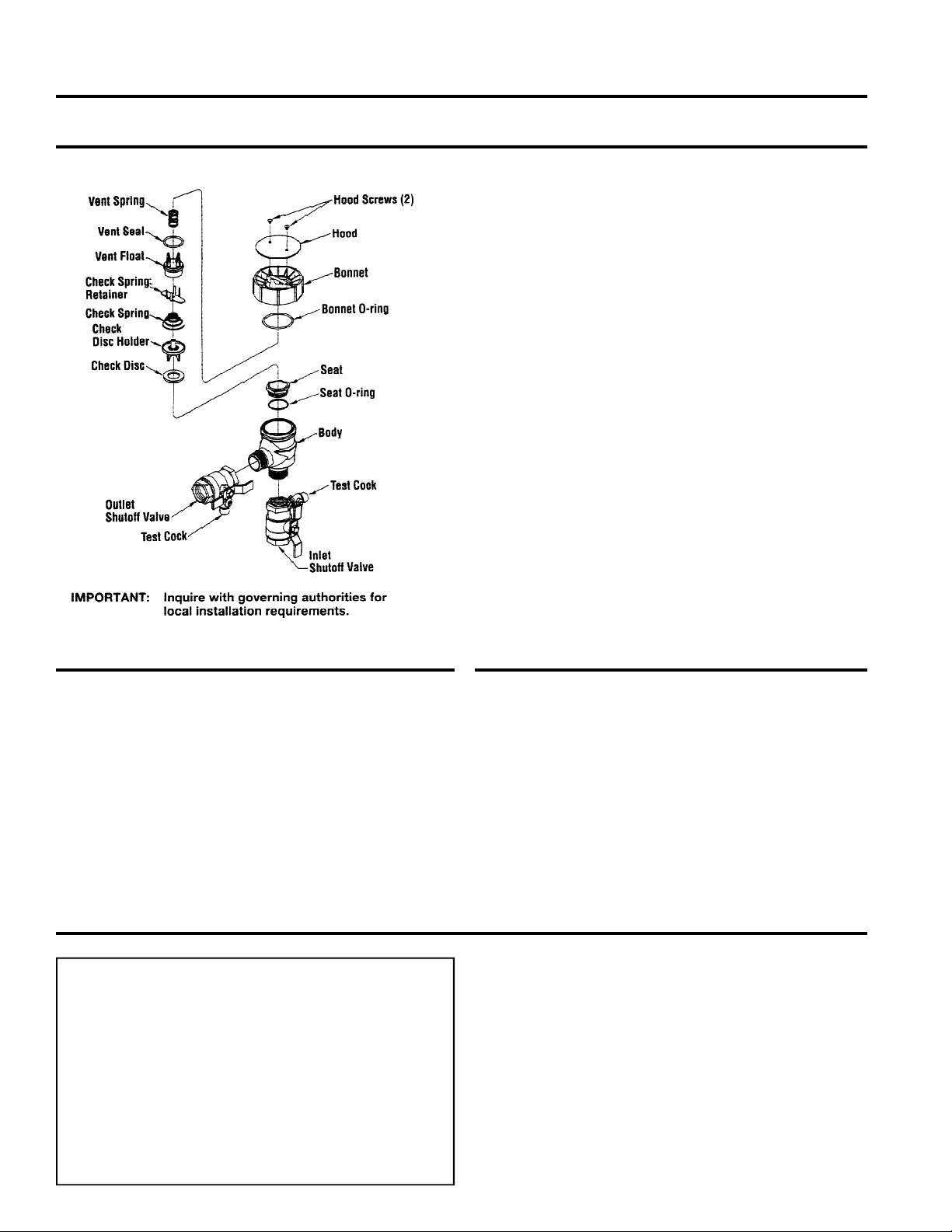
A200 REPAIR KITS
Check Kit: Include Check disc assembly (disc and disc
holder), Bonnet, O-ring and Spring.
Vent Float Kits: Includes Float vent disc assembly, (vent
float, spring) and Bonnet O-ring.
Bonnet Assembly Kits: Include Bonnet, Bonnet O-ring
an Vent Spring.
Rubber Parts Kits: Include Vent disc, Check disc and
Bonnet O-ring.
Seal Kits: Include Seat, Seat O-ring and Bonnet O-ring.
Disassembly:
1. Shut off the supply pressure and drain the valve.
2. Remove the two hood screws and the hood.
3. Place a wrench on the parallel flats of bonnet and stem
assembly. Turn counter clockwise and remove.
4. Remove the vent assembly.
5. Press down on the spring retainer and disengage it from the
retaining lugs. Then turn 90º and remove.
6. Remove the spring retainer and spring. Note that the large
diameter of the spring is down on the guide assembly.
7. Remove the check disc holder and guide assembly.
8. Disassemble the check disc holder assembly.
Reassembly:
Reassemble in the reverse order utilizing the new parts from
the repair kit.

Other AMES Control Unit manuals

AMES 2000 CIV Series Setup guide

AMES

AMES 2000 CIV Series Setup guide

AMES SILVER BULLET 2000SS Series User manual

AMES

AMES SILVER BULLET 2000SS Series User manual

AMES Colt Series Use and care manual

AMES

AMES Colt Series Use and care manual

AMES 2000B Series User manual

AMES

AMES 2000B Series User manual

AMES SILVER BULLET 2000SS Series User manual

AMES

AMES SILVER BULLET 2000SS Series User manual

AMES 1000SS Series User manual

AMES

AMES 1000SS Series User manual

AMES Maxim M300 Series Setup guide

AMES

AMES Maxim M300 Series Setup guide

AMES Colt Series Instruction Manual

AMES

AMES Colt Series Instruction Manual

AMES 972GD-19 Installation and operating instructions

AMES

AMES 972GD-19 Installation and operating instructions

AMES 910GD-01 Installation and operating instructions

AMES

AMES 910GD-01 Installation and operating instructions

AMES 2000SS Series Instruction Manual

AMES

AMES 2000SS Series Instruction Manual

AMES 400 Series User manual

AMES

AMES 400 Series User manual

Popular Control Unit manuals by other brands

Rauch QUANTRON-A instruction manual

Rauch

Rauch QUANTRON-A instruction manual

Siemens LOK16 Series manual

Siemens

Siemens LOK16 Series manual

Panasonic CF-BAS04GU operating instructions

Panasonic

Panasonic CF-BAS04GU operating instructions

LinMot FM01-48 installation guide

LinMot

LinMot FM01-48 installation guide

Tyco DV-5A manual

Tyco

Tyco DV-5A manual

NI PXIe-8623 SAFETY, ENVIRONMENTAL, AND REGULATORY INFORMATION

NI

NI PXIe-8623 SAFETY, ENVIRONMENTAL, AND REGULATORY INFORMATION

Bristan OP TS1503 EL C Installation instructions and user guide

Bristan

Bristan OP TS1503 EL C Installation instructions and user guide

YUKEN KOGYO ELDFG-01EH 10 Series instruction manual

YUKEN KOGYO

YUKEN KOGYO ELDFG-01EH 10 Series instruction manual

Belkin F1DE101H Quick installation guide

Belkin

Belkin F1DE101H Quick installation guide

Danfoss EVUL 1 installation guide

Danfoss

Danfoss EVUL 1 installation guide

GEM 567 servoDrive operating instructions

GEM

GEM 567 servoDrive operating instructions

pizzato CS MP201M0 quick start guide

pizzato

pizzato CS MP201M0 quick start guide

SDMO MICS Telys Instructions for use

SDMO

SDMO MICS Telys Instructions for use

Elvaco CMi2130G3 Quick manual

Elvaco

Elvaco CMi2130G3 Quick manual

CREVIS GT-5352 user manual

CREVIS

CREVIS GT-5352 user manual

WEG SSW900-CPN-IO-N Installation, configuration and operations guide

WEG

WEG SSW900-CPN-IO-N Installation, configuration and operations guide

GEA VARIVENT DN 25 Operating	 instruction

GEA

GEA VARIVENT DN 25 Operating instruction

GE Ziton ZP3-ECU Maintenance manual

GE

GE Ziton ZP3-ECU Maintenance manual

manuals.online logo
manuals.online logoBrands
  • About & Mission
  • Contact us
  • Privacy Policy
  • Terms and Conditions

Copyright 2025 Manuals.Online. All Rights Reserved.