Amewi ATX6 User manual

ATX6
Technical updates and additional programming examples available at http://amxracing.de
DIGITAL 6-CHANNEL RC-SYSTEM
INSTRUCTION MANUAL

ATX6
1
INTRODUCTION
Thank you for choosing AMX-Racing 2,4GHz 6-Kanal pistol grip radio ATX6.
ATX-6 is a professional 6 channels transmitter, sells with receiver which with gyro integrated and HV
servo supported.
ATX6, work with FHSS spread spectrum and 67 channels pseudo frequency sequence hopping, both
transmitter and receiver use industrial chip ensure superior anti-interference ability both at the same
frequency band and different frequency band and anti-sparks interference ability. Ground control
distance is up to 400 meters.
Suggestion: In order to fully enjoy the benefits of this remote-control equipment and ensure safety,
please read the introduction carefully and set up the device as described below
We hope you enjoy using the ATX6 remote-control system.
If you found any problems during the operation process, please refer to the manual. If the problem still
exists, you could contact our dealers to find out the way to solve it.
Due to unforeseen changes in production procedures, the information contained in this manual is subject to
change without notice.
For more Information please check our Website at: https://amxracing.de.
Support & Service:
Support and Service: It is recommended to have your AMXRacing equipment serviced annually during your
hobby’s “off season” to ensure safe operation. Please be sure to regularly visit the Service and Support web
site at www.radiolink.com. This page includes extensive programming, use, set up and safety information.
Any technical updates and manual corrections will be available on this web pages. If you do not find the
answers to your questions there, please see the end of our contact area for information on contacting us
via email for the most rapid and convenient response.

ATX6
2
Important Safety Notice:
The following two symbols will appear in this manual(please pay attention to the paragraph with these
two symbols labelled.
Prohibition Testing and confirmation
Do not use in bad weather such as rainy or thundering to assure the safety of you and others.
You need to turn the throttle channel (CH2) and inch switch to the lowest before you use. Then switch on
the transmitter, finally connect the receiver.
The sequence to shut down is that turn off the receiver power first, and then shut down the transmitter.
If the above operations are reverse, it might lead to uncontrolled situation and cause accidents.
The transmitter needs to be powered by 8 AA batteries or 2S-4S LiPo batteries. Please check the voltage
of batteries before using, as it might lead to uncontrolled situation and accidents when the voltage is
lacked. So, you must change the battery or recharge them in time.
WARNING!!!
This product is not a toy and is not suitable for children under the age of 18. Adults should keep the
product out of the reach of children and exercise caution when operating this product in the presence of
children.
Please don't run in the rain! Rain or moisture may enter the transmitter internal through gaps in the antenna
and cause your car to instability even out of control. If inevitable will run in the wet weather (such as game),
please be sure to use plastic bags or waterproof cloth to cover your transmitter, please don't run if there is
lightning!

ATX6
3
INHALT
1. Introduction and Service ………………………………………………………………………………………………………………………………………….1
2. Safety Notice and Warnings ……………………………………………………………………………………………………………………………………2
3. Pistol Grip Control System ……….……………………………………………………………………………………………………………………………..4
3.1 Transmitter ………………………………………………………………………………………………………………………………………………………..5
3.2 Receiver ….……….…………………………………………………………………………………………………………………………………………………6
3.2.1 Receiver Installation and Binding …………………………………………………………………………………………………………7
3.2.2 Working Mode ………………………………………………………..…………………………………………………………………………….7
3.2.3 How to Turn On Gyro Function …………..………………………………………………………………………………………………..7
4. ATX6 Functions …………………………………………………………………………………………………………………………………………………………9
4.1 Display when Power Switch Turned on ……………………………………………………………………………………………………………9
4.2 Language Select „LANGUAGE“ …………….…………………………………………………………………………………………………………10
4.3 Model Select „MODEL“ …………………………………………………………………………………………………………………………………….10
4.4 End Point Adjuster „EPA“ .………………….…………………………………………………………………………………………………………….10
4.5 Steering EXP „STEXP“ ………….…..………………..…………………………………………………………………………………………………….11
4.6 Steering Speed „STSPD“ …………………………..….………………………………………………………………………………………………….12
4.7 Throttle EXP „THEXP“ ……………………………………………………………………………………………………………………………………..12
4.8 Throttle Speed „THSPD“ ………………….……………………………………………………………………………………………………………….14
4.9 A.B.S Brake „A.B.S“ …………………………………………………………………………………………………………………………………………..16
4.10 Throttle Acceleration „ACCEL“ ……………………………………………….…………………………………………………………………….19
4.11 Idle-Up „IDLUP“ ………………………………………………………………………………………………………………………………………………..20
4.12 Sub-Trim „SUBTR“ …………………………………………………………………………………………………………………………………………..20
4.13 Servo Reverse „REV“ …………….………………………………………………………………………………………………………………………..21
4.14 Steering Dual Rate/Throttle Dual Rate „D/R“ ……………………………………………………………………………………………….21
4.15 ATL Function „ATL“ …………………………………………………………………………………………………………………………………………22
4.16 Programmable Mixes „PMIX“ ………………………………………………………………………………………………………………………..23
4.17 Channel 3 Position „AUX“ ……………………………………………………………………………………………………………………………..24
4.18 Model Name „NAME“ ……….…………………………………………………………………………………………………………………………….25
4.19 Low Voltage Alarm ………………………………………………………………………………………………………………………………………….25
4.20 Gyro Sensitivity ……………….………………………………………………………………………………………………………………………………26
4.21 Fail Safe ……………………………………………………………………………………………………………………………………………………………26
4.22 Reset Function „RESET“ ……………..………………………………………………………………………………………………………………….27

ATX6
4
3. PISTOL GRIP CONTROL SYSTEM
ATX6, Transmitter with STM32F103RB Chip, receiver RX6FG with 32-Bit Industrial chip. 12ms only form
transmitter to the receiver, thus provide control synchronous and perfect performance. FHSS and 67
channels pseudo random frequency sequence hopping makes the ATX6 have superior anti-interference
ability both at the same frequency band and different frequency bands.
Control distance is up to 400 meters.
3.1 Transmitter
Switch (CH6)
Throttle trim
CH3 trim
Switch (CH5)
Steering wheel
Steering trim
VR CH 3/4
Switch CH 3/4
Menu Buttons
Antenna
LCD Display

ATX6
5
Specifications:
Size: 213 x 117 x 115,5mm
Frequency: 2,4GHz ISM Band 2400MHz –2483,5MHz
Channels: 6
Transmission speed: 12ms
Channel resolution: 4096 the regular Jitter is 0,5µs
Model: Cars and Boats
Spread Spectrum: FHSS 64 Channels Pseudo Random Frequency Sequence Hopping
Model Memory Storage: 10
Antenna length: 106mm
Control distance: 400m
LCD Screen: 128x64 Resolution LCD Backlight
Transmitter operating Voltage: 4,8 –15,0V
Transmitter Batterie: 4AA 1,5V or 2-4S Lithium battery
Transmitter operating current: 80-120mA
RF-Power: < 20dbm
Low voltage alarm: lower than 4,6V, can be set when using 2-4S Lithium battery.
Receiver: RX6F, RX6FG
Simulator Port
USB-Upgrade Port
On-Off Switch
Throttle Trigger

ATX6
6
3.2 Receiver
ATX6 sells with RX6FG, 2.4GHz 6 channels receiver, gyro integrated and HV servo supported.
Specification:
Size: 35x20x13mm
Channels: 6
Modulation mode: GFSK
Spread Spectrum: FHSS
Antenna length: 210mm
Control distance: more than 400m
Power supply: 4,8-15V. 4x AA batteries 1,5V or 2-4S Lithium battery
Frequency: 2,4GHz ISM Band (2400MHz ~ 2483,5) MHz
Channel resolution: 4096, regular jitter 0,5µs
Work current: 30mA

ATX6
7
3.2.1 Receiver Installation and Binding
How to Match Code with Transmitter.
1. Put the transmitter and the receiver close to each other within 50 centimetres. 2. Turn on the transmitter,
then power on the RX6FG. 3. There is a black button on the RX6FG, press the binding button twice in two
seconds and release, receiver light starts blinking, after about blinking 8 times, match code success then
receiver signal LED always on! Attention: RX6FG default have not turn on the gyro function. Make sure the
RX6FG keep motionless when power on it, because the RX6FG will do the self-test. RX6FG with two indicate
LED, green LED on indicate normal working mode while both green and red LED on indicate gyro function
working mode.
3.2.2 Working Mode
The receiver has two working modes:normal working mode and gyro function working mode.
Normal Working Mode
Green LED, gyro will not be working.
Gyro Function Working Mode
Both green and red LED on. Receiver with gyro integrated to hold the vehicle in a straight line during
aggressive acceleration and braking or get bumped around by rough terrain. Receiver with gyro integrated
to keep the uni-direction and anti-slip.
3.2.3 How to Turn On Gyro Function
Quick press the ID SET switch two times within 1 second, the LED change from green to red means gyro
function has turn on.
Gyro Function Setup
Integrated Gyro, is used to assure the stability of cars on turning status; and keep on straight running even
the cars get some mechanical phantom. Gyro function can be enabled or disabled.
Gyro enabled
Gyro present disabled, and it enters post indication status. There are two indicators on the receiver. The
green one shows the receiver status and the red one is for gyro. When the led turns on, the gyro is enabled,
and the led turns off, gyro disabled.
Gyro enabled forward
Cars can be drove forward and backward, gyro is enabled forward or backward correspondingly. Like the
EP cars, different connection will make different direction, the gyro is ensured to be enable forward.
Gyro reverse
Same as a plane has reverse, car kit gyro has reverse as well. Only right set reverse gyro can act to correct.

ATX6
8
Setup
(1) Enable gyro
Press binding key three time (interval less than 1 second), the red LED will flash three time, indicating
whether gyro is enabled.
(2) Gyro Sensitivity
Gyro sensitivity is predefined to adjust by channel three (factory set VR function), turning the VR switch
clockwise to raise sensitivity and anti-clockwise to decrease.
(3) Gyro forward
When the gyro is enabled, pull the throttle trigger and then release (make sure the car stops running), turn
the car right or left without changing steering wheel, if the servo will not follow with, it shows gyro is set
backward. Press the binding switch one time less than 1 second, the LED flashes red once, gyro is changed
to act forward.
(4) Gyro reverse
Set the gyro forward, turn the car right or left to see whether gyro functions. The wheel will turn left when
the car is turned right, and the wheel turns right when the car is turned left. If the gyro acts counter, press
the binding switch two time, the LED flashes two time red, the gyro reverse is corrected.
Installation of receiver antenna
(1) The antenna must be kept as straight as possible. Otherwise it will reduce the effective range.
(2) Large model aircraft may of some metal part interfering signal; in this case the antennas should be
placed at both sides of the model. Then the best RF signal condition is obtained at any attitude.
(3) The antennas must be kept away from conductive materials, such as metal and carbon by at least a half
inch. The coaxial part of the antennas does not need to follow these guidelines, but do not bend it in a small
radius.
(4) Keep the antennas away from the motor, ESC,
and other noise sources as much as possible.
(5) Press and hold the Easy Link (ID SET) one
second, now the receiver starts work.
(6) After all the above steps finished, the LED
indicator will turn and keep in red/green.
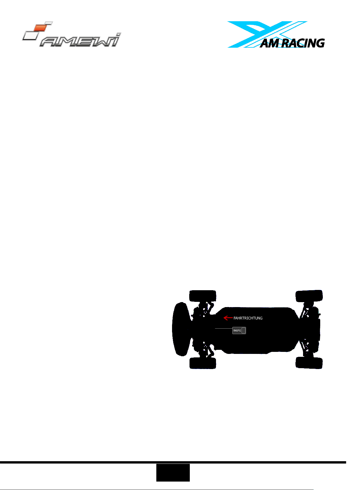
(7) The receiver can be packed by sponge or
foam for shocking proof when it is installed to the
model. After all the above steps finished, turn off
the transmitter and then power it on, now the program functions to assure it under control of transmitter
with a right connection.

ATX6
9
4. ATX6 Functions
4.1 Display when Power Switch Turned On
LCD-Screen
When you power on the transmitter RC6GS, LCD screen shows Model Name, Transmitter Name, Battery
Voltage, Steering Trim, Throttle Trim.
Model Name:
The system can store the data for 10 models, model name will show on the LCD when you power on the
transmitter. Please make sure the model name is the right one that you want. If the model name you chose
is not corresponding with your model, the settings should be wrong.
Battery Voltage:
In addition to the model, LCD can show the voltage of battery. When the voltage is lower than 4.6V, it would
start the low-voltage alarm, it would send out “DDD…” sounds, till the transmitter is power-off. When you
hear the low-voltage alert, you have no more than 4 minutes for controlling your model, please safely stop
your model before the uncontrolled situation. Please make sure the battery voltage is higher than this
voltage data while radio controlling.
Transmitter functions menu setting
When you want to browse or change a setting of transmitter, you should go into function menu setting
mode. Under function menu setting mode, you can set up Language. Select "LANGUAGE", Model Select
"MODEL", End Point Adjuster "EPA", Steering EXP "STEXP", Steering Speed "STSPD", Throttle EXP "THEXP",
Throttle Speed "THSPD", A.B.S. Function "A.B.S", Throttle Acceleration "ACCEL", Idle-Up "IDLUP", Sub-trim
"SUBTR", Servo Reverse "REV", Steering Dual Rate/Second. Dual Rate "D/R", ATL Function "ATL",

ATX6
10
Programmable Mixes "PMIX", Auxiliary, Channel 3,4, 5 and 6 "AUX",Model name "NAME", Reset function
"RESET".
4.2 Language Select "LANGUAGE"
Both English and German version menu are available for which is
convenient for German and English-speaking players to personalize
function menus.
(1) Access the function menu (By pressing “Exit” and “Enter” buttons
simultaneously and holding them down for one second), the
Language select function will be chosen.
(2) Press “Enter” button to get into “LANGUAGE” function interface.
(3) Use “(-)” or “(+)” key to select “German”or “English”, the selected
language will be with black shading effect.
(4) Press “Enter” button, the desired language is selected, and return
to the initial screen automatically.
4.3 Model Select "MODEL"
ATX6 can store model memories for ten models. Use this function to
call a new model.
(1) Access the function menu (By pressing “Exit” and “Enter” buttons
simultaneously and holding them down for one second), press
“Enter” key once, the Model select function will be chosen.
(2) Press “Enter” button, the current active model will be blinking.
(3) To activate a different model by pressing “(-)” or “(+)” button until
the desired model blinks.
(4) Press “Enter” button, the selected model stops blinking, now the
model has been selected.
(5) Return to the initial screen by pressing “Exit” button twice.
4.4 End Point Adjuster "EPA"
Use EPA when performing left and right steering angle adjustments,
throttle high side/brake side operation amount adjustment, and
channel 3 servo up side/down side operation amount adjustment
during linkage. Correct the maximum steering angle and left and right
steering angles when there is a difference in the turning radius due to
the characteristics, etc. of the vehicle.
Setting item (channel and direction)
ST: Steering (left/right)
TH: Throttle (forward/brake)
CH3: 3rd channel (left/ right)

ATX6
11
CH4: 4th channel (left/ right)
CH5: 5th channel (left/ right)
CH6: 6th channel (left/ right)
Steering EPA
ST: 0% ~ 120%
Initial value: 100%
AUX Servo EPA
CH3: 0% ~ 120%
Initial value: 100%
AUX Servo EPA
CH5: 0% ~ 120%
Initial value: 100%
Throttle EPA
TH: 0% ~ 120%
Initial value: 100%
AUX Servo EPA
CH4: 0% ~ 120%
Initial value: 100%
AUX Servo EPA
CH6: 0% ~ 120%
Initial value: 100%
End point adjustment
(1) Access the function menu (By pressing “Exit” and “Enter” buttons simultaneously and holding them
down for one second), press “(+)” button twice to choose EAP function.
(2) Press “Enter” button to get into EPA function interface, use “(-)” or “(+)” button to select the desired
setting item , press “Enter” key, the initial value of your selected setting item will blink, then you can press
“(-)” or “(+)” button to adjust the value of your selected setting item. (Note: In the interface of adjusting the
value, return to the initial value "100%" by pressing “(-)” and “(+)” buttons simultaneously for about 1
second.)
(3) Press “Enter” button, the adjusted value of your selected setting item stops blinking, now the value of
your selected setting item has been set.
(4) Return to the initial screen by pressing “Exit” button twice.
4.5 Steering EXP "STEXP“
This function is used to change the sensitivity of the steering servo around the neutral and both ends
position. It has no effect on the maximum servo travel. Adjust the sensitivity of direction wheel both in
neutral position and ends.
Setup Item
RATE: Steering EXP rate
Adjustment range: -100% ~ 0% ~ +100%
Initial value: 0%
0% ~ -100%: Sensitivity around neutral position is low, getting higher
when approaching ends.
0%: Sensitivity around the neutral and ends position is equal
0%~ + 100%: Sensitivity around neutral position is high, getting lower
when approaching ends

ATX6
12
Steering operation curve adjustment
(1) Access the function menu (By pressing “Exit” and “Enter” buttons simultaneously and holding them
down for one second), press “(+)” button three times to choose EAP function.
(2) Press “Enter” button to get into STEXP function interface, press “Enter” key and the initial value of the
rate will blink, then you can press “(-)” or “(+)” button to adjust the value and the curve of the rate shown in
the figure will change correspondingly. (Note: In the interface of adjusting the value, return to the initial
value "0%" by pressing “(-)” and “(+)” buttons simultaneously for about 1 second.)
(3) Press “Enter” button, the adjusted value of the rate stops blinking, now the value of the rate has been
set.
(4) Return to the initial screen by pressing “Exit” button twice. Note: The Vertical cursor shown in the figure
moves in step with steering wheel operation.
4.6 Steering Speed "STSPD“
Quick steering operation will cause momentary under steering, loss
of speed, or spinning. This function is effective in such cases.
Setup item:
TURN: turn direction
RETURN: return to the original direction
Adjustment range
0% ~ 100% (each direction)
Bei 100% there is no delay
Steering servo delay
(1) Access the function menu (By pressing “Exit” and “Enter” buttons simultaneously and holding them
down for one second), press “(+)” button four times to choose STSPD function.
(2) Press “Enter” button to get into STSPD function interface, press “(-)” or “(+)” button to select setup item,
then press “Enter” key and the initial value of selected setup item will blink.
(3) Use “(-)” or “(+)” button to adjust the value of the selected setup item. (Note: In the interface of adjusting
the value, return to the initial value "100%" by pressing “(-)” and “(+)” buttons simultaneously for about 1
second.)
(4) Press “Enter” button, the adjusted value of the selected setup item stops blinking, now the value of the
selected setup item has been set.
(5) Return to the initial screen by pressing “Exit” button twice.
4.7 Throttle EXP "THEXP“
This function makes the throttle high side and brake side direction servo operation quicker or milder. It has
no effect on the servo maximum operation amount. For the high side, selection from among three kinds of
curves (CRV/VTR/EXP) is also possible.
The curve can be divided into: Five dots throttle curve adjustment, Single point adjustment, Exponential

ATX6
13
curve adjustment, Braking index curve adjustment. To elevation point, we can select (Exponential
curve/Single point curve/Five points curve).
Curve point adjustment (select five points 1-5)
(1) Press "Enter" button, the curve point value start flashing, then press "(-)" and "(+)" button to adjust the
starting value.
(2) Press "Enter" button, starting value stop flashing, adjustment is completed.
(3) Press "Exit" button for two times, back to the initial interface.
Throttle curve adjustment
Adjustment method for CRV curve
Setup Items
Mode: ON/OFF
RATE: 0% ~ 100%
(1) Enter the function menu and use “(-)” or “(+)” button to access
THEXP function. Select “FWD-CRV” function.
(2) Press “(-)” or “(+)” button to select curve points 1~5 for curve
point adjustment that you want, from the graph you will clearly see
the changes you have made.
Adjustment method for VTR curve
Adjustment range
TG.P: 20-80
RATE: -100 ~ 0 ~ +100
(1) Enter the function menu and use “(-)” or “(+)” button to access
THEXP function. Select “FWD-VTR” function.
(2) Press “(-)” or “(+)” button to select RATE for forward side
adjustment that you want, when the “MODE” value is “OFF” the VTR
will not work, only the “MODE” value set to “ON” the VTR function is
available. From the graph you will clearly see the changes you have
made on TG.P and RATE.
Adjustment method for EXP curve
Setup items
MODE: EXP turn on or turn off
RATE: EXP rate
Adjustment range
MODEL: OFF/ON
RATE: -100 ~ 0 ~ +100

ATX6
14
(1) Enter the function menu and use “(-)” or “(+)” button to access THEXP function, then select the “FWD-
EXP” function.
(2) Press “(-)” or “(+)” button to select RATE for adjustment, set the most comfortable value you want. From
the graph you will clearly see the changes you have made on the EXP RATE, also move the trigger to check
the throttle status.
Adjustment method for BRK-EXP curve
Setup Items
RATE: BRK-EXP rate
Adjustment range
RATE: -100 ~ 0 ~ +100
0 ~ -100: flat braking
0: uniform braking
0 ~ +100: sensitive braking
Brake side adjustment (select BRK)
(1) Press “Enter” key, the current BRK value will blink, use “(+)” button
to adjust the + side when you want to quicker the rise and use “(-)” button to adjust the -side when you want
to make the rise milder. (Note: In the interface of adjusting the value, return to the initial value "0" by
pressing “(-)” and “(+)” buttons simultaneously for about 1 second.)
(2) Press “Enter” button, the adjusted BRK value stops blinking, now the BRK value has been set.
(3) When ending setting, return to the initial screen by pressing “Exit” button twice.
4.8 Throttle Speed „THSPD“
Throttle servo delay
Sudden trigger operation on a slippery road only causes the wheels to spin and the vehicle cannot
accelerate smoothly. Setting the throttle speed function reduces wasteful battery consumption while at the
same time permitting smooth, enjoyable operation.
Operation
Throttle servo (amp) operation is delayed so that the drive wheels will not spin even if the throttle trigger is
operated more than necessary. This delay function is not performed when the throttle trigger is returned
and at brake operation.
OFF: Speed1 or speed2 can be selected.
OFF means shut down the throttle speed function

ATX6
15
Adjustment method for SPEED1
Setup items
MODE: Speed type selection
ALL: Speed adjustment
Adjustment range
0 ~ 100 (each direction)
Bei 100 there is no delay
(1) Enter the function menu and use “(-)” or “(+) ” button to access
THSPD function.
(2) Press “Enter” button to get into THSPD function interface.
(3) If initial MODE setup item is SPEED1, {if initial MODE setup item is SPEED2 or OFF, you need to select
SPEED1 by pressing “(-)” or “(+)” button to select MODE setup item, then press “Enter” key, SPEED2 or OFF
will blink, press “(-)” or “(+)” button, when the blinking SPEED2 or OFF change to blinking SPEED 1, press
“Enter” key, SPEED1 will stop blink, now SPEED1 is selected}, press “(-)” or “(+)” button to select ALL setup
item, then press “Enter” key, the initial value will blink, use “(-)” or “(+)” button to adjust the delay of the
entire throttle forward side range. (Note: In the interface of adjusting the value, return to the initial value
"100" by pressing “(-)” and “(+)” buttons simultaneously for about 1 second.) Press “Enter” button, the
adjusted value stops blinking, now the value has been set.
(4) When ending setting, return to the initial screen by pressing “Exit” button twice.
Adjustment method for SPEED2
Setup items
MODE: Speed type selection
LOW: Low side range speed adjustment
HIGH: High side range speed adjustment
TGP1: Low and medium speed switching point
Adjustment range
Low: 0 ~ 100
High: 0 ~ 100
At 100 there is no delay
TGP1: 0 ~ 100
(1) Enter the function menu and use “(-)” or “(+)” button to access THSPD function.
(2) Press “Enter” button to get into THSPD function interface.
(3) If initial MODE setup item is SPEED 2, { if initial MODE setup item is SPEED 1, you need to select SPEED2
by pressing “(-)” or “(+)” button to select MODE setup item, then press “Enter” key, SPEED1 or OFF will blink,
press “(-)” or “(+)” button, when the blinking SPEED1 or OFF change to blinking SPEED2, press “Enter” key,
SPEED2 will stop blinking, now SPEED2 is selected}, press “(-)”or“(+)” button to select "LOW" or "HIGH"
delay adjustment or “TGP1” speed switching point adjustment.
(4) Press “Enter” key to confirm "LOW" or "HIGH" or “TGP1” setup item, and the value of your selected setup
item will blink. Use “(-)” or “(+)” button to adjust the value. (Note: In the interface of adjusting the value,
return to the initial value (the initial value of LOW and HIGH is “100”, the initial value of TGP1 is “30”) by

ATX6
16
pressing “(-)” and “(+)” buttons simultaneously for about 1 second.) Press “Enter” button, the adjusted value
stops blinking, now your selected value has been set.
(5) When ending setting, return to the initial screen by pressing “Exit” button twice.
4.9 A.B.S. Function „A.B.S“
Pulse brake
When the brakes are applied while cornering with a 4 Wheel Drive or other type of vehicle, under-steer may
occur. The generation of under-steer can be eliminated, and corners can be smoothly cleared by using this
function.
Operation
When the brakes are applied, the throttle servo will pulse intermittently. This will have the same effect as
pumping the brakes in a full-size car.
The brake return amount, pulse cycle, and brake duty can be adjusted.
The region over which the ABS is effective can be set ac-cording to the steering operation. (Mixing
function)
Setup items
ABP: Brake return amount
DLY: Delay amount
CYC: Cycle speed
TGP: Operation point
DTY: Cycle duty ratio
STM: Steering mixing
ABP (Amount of brake return): Sets the rate at which the servo
returns versus trigger operation for brake release. When set to 0, the
ABS function is not Performed. When set to 50, the servo returns 50%
(1/2) of the trigger operation amount and when set to 100, the servo returns to the neutral position.
DLY (Delay): Sets the delay from brake operation to ABS operation. When set to 0, the ABS function is
activated without any delay. At 50%, the ABS function is activated after a delay of approximately 0.7 second
and at 100, the ABS function is activated after a delay of approximately 1.4 seconds.
CYC (Pulse speed): Sets the pulse speed (cycle). The smaller the set value, the faster the pulse cycle.
TGP (Trigger Point): Sets the trigger point at which the ABS function begins to operate at brake operation.
DTY (Cycle duty ratio): Sets the proportion of the time the brakes are applied and the time the brakes are
released by pulse operation. The ratio can be set to +3 ~ 0 ~ -3 in 7steps.
STM (Steering mixing): Sets ABS operation ON/OFF according to the steering operation range.

ATX6
17
A.B.S. Function adjustment
Enter the function menu and use “(-)” or “(+)” button to access A.B.S function, then press “Enter” button to
get into A.B.S function interface.
(1) Brake return amount adjustment Select the setting item "ABP" by pressing “(-)” or “(+)” button, then
press “Enter” key and the initial value of “ABP” will blink. Use “(-)” or “(+)” button to adjust the return
amount. (Note: In the interface of adjusting the value, return to the initial value "50" by pressing “(-)” and
“(+)” buttons simultaneously for about 1 second.)
Press “Enter” button, the adjusted value stops blinking, now the value has been set.
Brake return amount (ABP)
0 ~ 50 ~ 100
Initial value: 50
Brake return amount (ABP) is influenced by the "EXP" rate on the brake side.
(2) Delay amount setup Select the setting item "DLY" by pressing “(-)” or “(+)” button, then press “Enter” key
and the initial value of “DLY” will blink. Use “(-)” or “(+)” button to adjust the delay amount. (Note: In the
interface of adjusting the value, return to the initial value "0" by pressing “(-)” and “(+)” buttons
simultaneously for about 1 second.) Press “Enter” button, the adjusted value stops blinking, now the value
has been set. "0": A.B.S. function performed without any delay "50": A.B.S function performed after an
approximate 0.7 sec delay "100": A.B.S. function performed after an approximate 1.7 secs delay
Delay amount (DLY)
0 ~ 100
Initial value: 0
(3) Pulse speed adjustment
Select setting item "CYC" by pressing “(-)” or “(+)” button, then press “Enter” key and the initial value of
“CYC” will blink. Use “(-)” or “(+)” button to adjust the pulse speed (cycle). (Note: In the interface of
adjusting the value, return to the initial value "5" by pressing “(-)” and “(+)” buttons simultaneously for about
1 second.) Press “Enter” button, the adjusted value stops blinking, now the value has been set.
- The smaller the set value, the faster the pulse speed.
Cycle Speed (CYC)
0 ~ 30
Initial value: 5
(4) Operation Point Setup
Select setting item "TGP" by pressing “(-)” or “(+)” button, then press “Enter” key and the initial value of
“TGP” will blink. Use “(-)” or “(+)” button to adjust the operation point. (Note: In the interface of adjusting the
value, return to the initial value "30" by pressing “(-)” and “(+)” buttons simultaneously for about 1 second.)
Press “Enter” button, the adjusted value stops blinking, now the value has been set. - Sets the throttle
trigger position at which the A.B.S. function is performed. The number is the 100 display with the full brake
position made 100%.
Operation point (TGP)
0 ~ 100
Initial value: 30

ATX6
18
(5) Cycle duty ratio setup
Select setting item "DTY" by pressing “(-)” or “(+)” button, then press “Enter” key and the initial value of
“DTY” will blink. Use “(-)” or “(+)” button to adjust the duty ratio. (Note: In the interface of adjusting the
value, return to the initial value "0" by pressing “(-)” and “(+)” buttons simultaneously for about 1 second.)
Press “Enter” button, the adjusted value stops blinking, now the value has been set.
"-3": Brake application time becomes shortest. (Brakes lock with difficulty)
"+3": Brake application time becomes longest (Brakes lock easily)
(Remark) For low grip set at the - side and for high grip set at the + side.
Duty ratio (DTY)
-3 ~ 0 +3
Initial value: 0
(6) Steering mixing setup
Select setting item "STM" by pressing “(-)” or “(+)” button, then press “Enter” key and the initial value of
“STM” will blink. Use “(-)” or “(+)” button to adjust the steering mixing range. (Note: In the interface of
adjusting the value, return to the initial value "OFF" by pressing “(-)” and “(+)” buttons simultaneously for
about 1 second.)
Press “Enter” button, the adjusted value stops blinking, now the value has been set.
-Sets the range within which the A.B.S. function is performed relative to steering wheel operation.
Steering operation
When steering mixing is set and steering operation enters the set range, "*" is displayed in front of the
number. When mixing is OFF, the A.B.S function can operate over the entire steering range. When ending
setting, return to the initial screen by pressing “Exit” button twice.
Steering mixing (STM)
OFF, N10 ~ N100, E10 ~ E100
Initial value: OFF

ATX6
19
4.10 Throttle Acceleration "ACCEL“
Function which adjusts the movement characteristic from the throttle neutral position
The servo will jump to the input position at its maximum possible speed. Unlike exponential, which adjusts
the whole throttle movement into a curve, throttle acceleration simply "jumps" away from neutral and then
leaves the remaining response linear.
Setup item
FWRD: Forward side acceleration amount
BRAK: Brake side acceleration amount
Throttle acceleration adjustment
Enter the function menu and use “(-)” or “(+)” button to access ACCEL
function, then press “Enter” button to get into ACCEL function
interface.
(1) Forward acceleration amount adjustment Press “(-)” or “(+)”
button to select “FWRD”, press “Enter” key to confirmand the initial
value of “FWRD” will blink, then use “(-)” or “(+)” button adjust the acceleration amount. (Note: In the
interface of adjusting the value, return to the initial value "0%" by pressing “(-)” and “(+)” buttons
simultaneously for about 1 second.)
Press “Enter” button, the adjusted value stops blinking, now the value has been set.
Forward acceleration amount (FWRD)
0% ~ 100%
Initial value: 0%
(2) Brake side acceleration amount adjustment
Press “(-)” or “(+)” button to select “BRAK”, press “Enter” key to confirm and the initial value of “BRAK” will
blink, then use “(-)” or “(+)” button adjust the acceleration amount.
(Note: In the interface of adjusting the value, return to the initial value"0%" by pressing “(-)” and “(+)” buttons
simultaneously for about 1 second.)
Press “Enter” button, the adjusted value stops blinking, now the value has been set.
"0%": No acceleration
"100%": Maximum acceleration
(Brake side maximum steering angle) Brake side acceleration amount (BRAK)
Brake side acceleration amount (BRAK)
0% ~ 100%
Initial value: 0%
When ending setting, return to the initial screen by pressing “Exit” button twice.
Table of contents
Other Amewi Remote Control manuals
Popular Remote Control manuals by other brands

Ecolink
Ecolink WST-102 Installation guide & user manual

RVLock
RVLock R005V manual

Philips
Philips SRU 5086 Instructions for use

Zodiac
Zodiac Z200 Instruction manual and spare parts list

Map
Map KF297 Programming instructions

Mitsubishi Electric
Mitsubishi Electric Ecodan PAR-WT50R-E Installation and setting manual