00200200
100100
5050 150150
STARTER
AMPS
STARTER
AMPS
00224466881010
MILLIAMPERE
METER
MILLIAMPERE
METER
003030
1010 2020
ALTERNATOR
VOLTAGE
ALTERNATOR
VOLTAGE
003030
1010 2020
ALTERNATOR
AMPS
ALTERNATOR
AMPS
STARTER VOLTAGE
STATOR VOLTAGE
0, unless W connected
then 7 to 8
STARTER VOLTAGE
STATOR VOLTAGE
0, unless W connected
then 7 to 8
STARTER AMPERAGE
0
STARTER AMPERAGE
0
4
a
m
p
4
a
m
p
BlueBlue
GreenGreen
RedRed
BAD DIODE LIGHT CHARGE LIGHT AUXILIARY LIGHTBAD DIODE LIGHT CHARGE LIGHT AUXILIARY LIGHT
MILLIAMPERE METER
6 or less
MILLIAMPERE METER
6 or less ALTERNATOR VOLTAGE
13 to 16
ALTERNATOR VOLTAGE
13 to 16
ALTERNATOR AMPERAGE
12 to 16
ALTERNATOR AMPERAGE
12 to 16
offoff offoff offoff
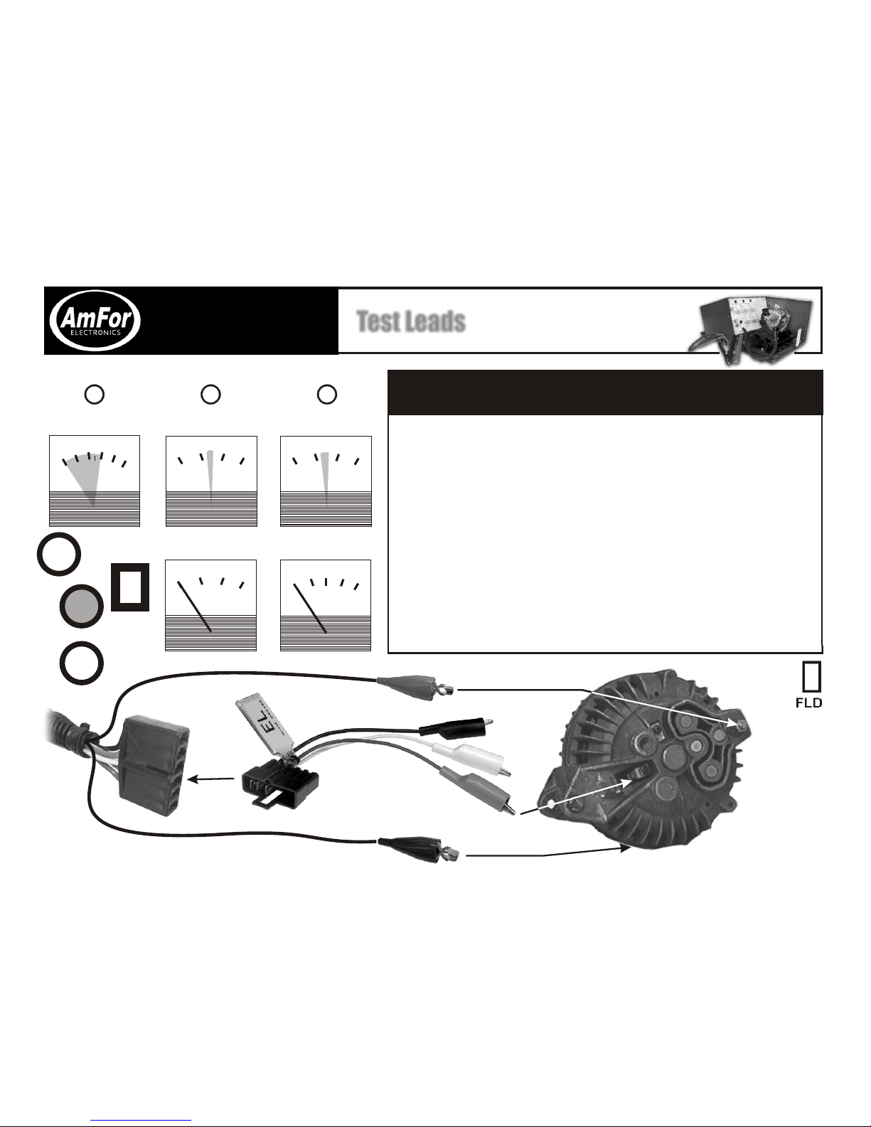
Test Lead BT
Test LeadsTest Leads
and
881 Alternator
Starter Test Bench
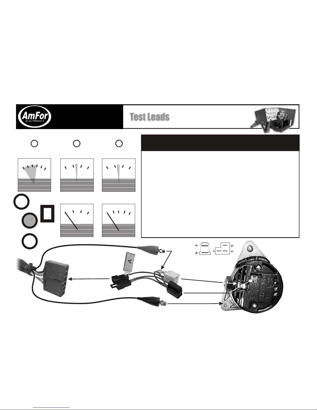
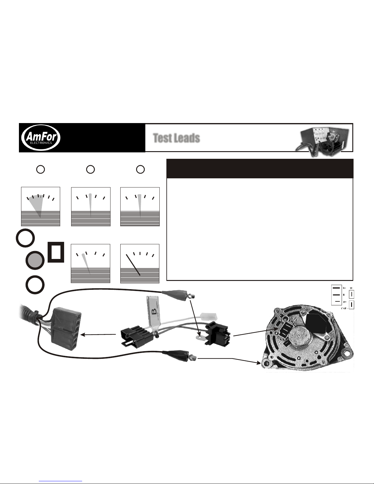
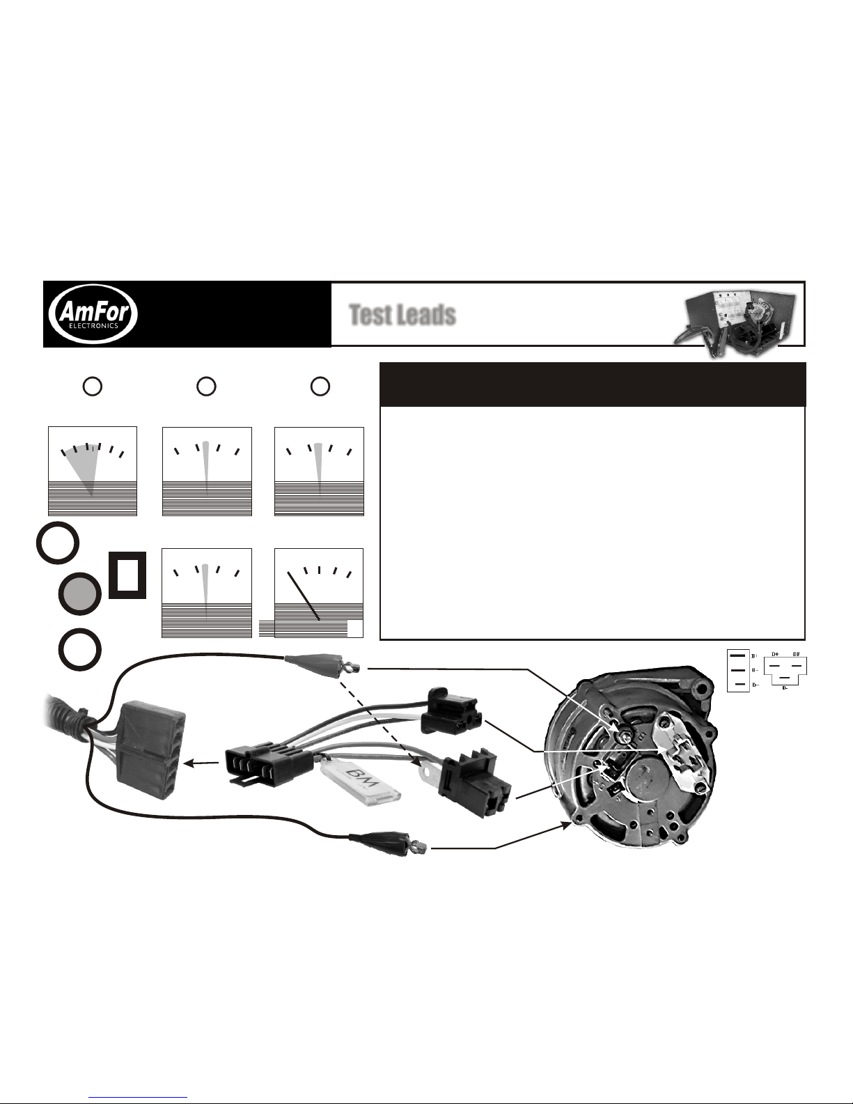
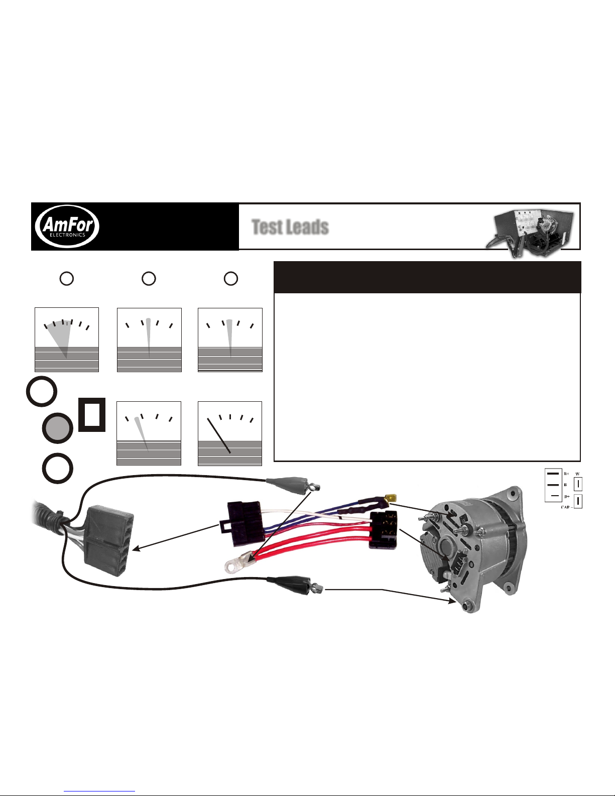
Many alternators use the same plug with different wiring. Please
refer to test lead chart for the correct test lead requirements!
1. Readings for a good alternator are in the shaded area. All meter
readings are ±5%.
2. Insert lead as shown below and slide alternator onto alternator
holder pin.
3. Install the belt making sure it is under the belt retaining clip. Slide
the green handle to the right, locking handle into retaining tab and
close the belt guard. Make sure to keep your fingers and clothing
free of the pulley and belt.
4.Turn on motor switch. The charge light on the panel should be lit.
If not, check and reset the circuit breaker on the front panel.
5. Press the GREEN test button MOMENTARILY and RELEASE.
Observe meters for proper readings. Hold for no more than 3
seconds.
Red clip
Black clip
003030
1010 2020
STARTER / STATOR
VOLTAGE
STARTER / STATOR
VOLTAGE
Pdc/nwr/inv/881/881-manual/green/889-BT.cdr
W terminal, connected only
when W spade is present
on alternator