Amit APT4015A Installation manual

apt4015ax_g_en_100
APT4015A(x)
Panel computer
Operation manual
Version 1.00

APT4015A(X)
apt4015ax_g_en_100 2/49
AMiT, spol. s r. o. does not provide any warranty concerning the contents of this
publication and reserves the right to change the documentation without
obligation to inform anyone or any authority about it.
This document can be copied and redistributed under following conditions:
1. The whole text (all pages) must be copied without making any modifications.
2. All redistributed copies must retain the AMiT, spol. s r. o. copyright notice
and any other notices contained in the documentation.
3. This document must not be distributed for profit.
The names of products and companies used herein may be trademarks or
registered trademarks of their respective owners.
AMiT is a registered trademark.
Copyright (c) 2017, AMiT, spol. s r. o.
Producer: AMiT, spol. s r. o.
Naskové 1100/3, 150 00 Praha
amitomation.com

APT4015A(X)
3/49 apt4015ax_g_en_100
Contents Revision history..............................................................................................5
Related documentation...................................................................................5
1Introduction..........................................................................................6
2Technical parameters..........................................................................7
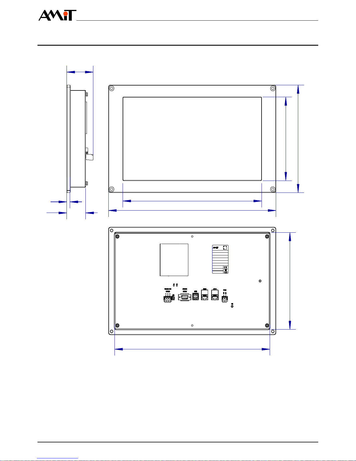
2.1 Dimensions...................................................................................................10
2.2 Recommended drawing symbol ...................................................................11
2.3 Block diagram...............................................................................................12
3Product marking ................................................................................13
3.1 Producer type label.......................................................................................14
4Conformity assessment ....................................................................15
4.1 Other tests....................................................................................................16
5Power supply......................................................................................17
5.1 Panel computer start up and shut down.......................................................17
6Processor module..............................................................................18
7Communication interface and peripherals......................................19
7.1 RS232 (COM1).............................................................................................19
7.2 RS485 (COM2).............................................................................................20
7.3 Ethernet........................................................................................................21
7.3.1 Connector RJ45............................................................................................22
7.4 USB..............................................................................................................23
7.5 Touch panel..................................................................................................23
7.6 mSATA.........................................................................................................23
7.6.1 mSATA replacement procedure ...................................................................24
Case cover removal......................................................................................24
Disconnect PE..............................................................................................25
Install the mSATA disk .................................................................................25
Connect PE ..................................................................................................26
Mounting cover.............................................................................................27
7.7 SD card ........................................................................................................27
7.7.1 SD card replacement procedure...................................................................27
Casing removal.............................................................................................28
Disconnect PE..............................................................................................28
Insert the SD card.........................................................................................29
Connect PE ..................................................................................................29
Mounting cover.............................................................................................30
8Mounting.............................................................................................31
8.1 Mounting instructions....................................................................................31
8.2 Mounting apertures.......................................................................................31
8.3 Installation principles....................................................................................34
9Software equipment...........................................................................36
9.1 APT4015A –Linux/GNU operating system ..................................................36
9.1.1 Description of the supplied operating system...............................................36

APT4015A(X)
apt4015ax_g_en_100 4/49
Touch panel..................................................................................................36
Backlight.......................................................................................................37
Temperature sensor.....................................................................................37
User LEDs....................................................................................................37
Ethernet........................................................................................................37
Serial interfaces............................................................................................38
9.1.2 Launching the APT4015A panel computer...................................................38
Creating a USB FLASH drive for installing the operating system.................38
Installation of operating system....................................................................39
9.1.3 Factory setting restoring...............................................................................39
9.2 APT4015AT –TouchDet ..............................................................................39
10 Factory settings .................................................................................40
Ethernet factory settings...............................................................................40
11 Ordering information and the package content..............................41
11.1 Package contents.........................................................................................41
12 Packaging...........................................................................................42
13 Storing.................................................................................................43
14 Maintenance .......................................................................................44
14.1 Backup battery..............................................................................................44
14.1.1 Battery replacement procedure ....................................................................44
Casing removal.............................................................................................44
Disconnect PE..............................................................................................45
Battery replacement .....................................................................................45
Connect PE ..................................................................................................46
Mounting cover.............................................................................................47
14.2 Cleaning .......................................................................................................47
15 Waste disposal...................................................................................49

APT4015A(X)
5/49 apt4015ax_g_en_100
Revision history
Document name: apt4015ax_g_en_100.pdf
Revision
Date
Changes author
Changes
100
30. 08. 2017
Rott O.
New document.
Related documentation
1. APT Flash Loader –User’s guide
file: apt-flash-loader_g_en_xxx.pdf
2. TouchDet –environment for visualisation and monitoring –Operation manual
file: touchdet_g_en_xxx.pdf
3. Application note AP0016 –Principles of RS485 interface usage
file: ap0016_en_xx.pdf
4. Application note AP0037 –Principles of Ethernet network usage
file: ap0037_en_xx.pdf
5. www.msc-technologies.eu –MSC Q7-BT processor core producer
6. www.microchip.com –producer of the resistive panel controller AR110
7. www.kernel.org –The Linux Kernel Archives
8. wiki.debian.org –Wikipedia for Debian

APT4015A(X)
apt4015ax_g_en_100 6/49
1 Introduction
APT4015A(x) is a panel computer built on a PC platform. It is intended to be
built-in into switchboard front panel.
The panel computer APT4015A(x) contains the main processor module with the
processor Intel®Atom™ (hereinafter referred to as the main CPU).
CPU Intel® Atom™E3815, Single core, 1.46 GHz
2 GB DDR3L RAM
4 GB SATA SLC eMMC
TFT LCD 15,6" interface (1366 × 768), LED backlight
Resistive touch panel
1× slot miniPCIe for mSATA
1×RS485 interface (galvanic isolation)
1× RS232 interface without galvanic isolation
2× USB with A-type USB connector
2× Ethernet interface 1 Gbps, connector RJ45
Nominal power supply voltage 24 V DC
The panel computer is designed to work within the whole operating temperature
range right after startup, without the need of tempering.
To avoid damage of electronics the computer switches automatically off
whenever critical temperature inside the system is reached.
On panel computer can run most of available operating systems. Please contact
AMiT technical support for information about current OS versions and support
for the OS launch.
Properties

APT4015A(X)
7/49 apt4015ax_g_en_100
2 Technical parameters
CPU
Intel®Atom™E3815, Single core, 1.46 GHz
RAM
2 GB, DDR3L SDRAM
FLASH memory
4 GB eMMC
LCD display
(1366 × 768) pixels, 15.6", 262k colours
Brightness, contrast
Typically 300 cd/m2, typically 500:1
Viewing angles
Typically 140 ° horizontally, 120 ° vertically
Backlight
LED
Backlight lifetime
50 000 hours 1)
1) Luminosity drop to 50 %, Ta = 25 °C.
Type
Resistive
Number of touches
Unspecified
Touching strength
Unspecified
Resistance to chemicals
Unspecified
The touch panel is intended to be operated by fingers or a tool without sharp
edges or by gloved fingers.
Quantity
1
Type
miniPCIe 2)
Capacity
Depending on the mSATA disk applied 2)
mSATA disk capacity
8 GB to 512 GB
2) Support only mSATA. mSATA disk is not included.
Quantity
1
Type
Micro SD (HC)
Capacity
Depending on the SD card applied3)
Memory card capacity range
2 GB to 128 GB
3) Micro SD card is not included.
Quantity
1
Operation indication
No
Overvoltage protection
Transil 600 W
Galvanic separation
Yes
Insulation strength
500 V AC / 1 minute 4)
Terminating resistor
120 Ω 5)
Recommended cabling
Shielded cable
Idle status definition 5)
to +5 V
to 0 V
820 Ω on the station
Maximum number of stations
32
Connection point
WAGO 231-303/102-000
Wire cross-section
0.08 mm2to 2.5 mm2
4) Insulation must not be used for separation of dangerous voltages
5) The idle status definition and termination are connected simultaneously.
CPU
Display
Note
Touch panel
Note
mSATA
Note
SD card
Note
RS485
Note

APT4015A(X)
apt4015ax_g_en_100 8/49
Quantity
1
Operation indication
No
Galvanic isolation
No
Recommended cabling
Shielded cable
Logical level 0 (input)
-30 V to +0.6 V
Logical level 1 (input)
+2.4 V to +30 V
Connection point
D-sub DE-9 plug,
connector fixing by UNC4-40 thread bolt
Quantity
2 6)
Operation indication
LED (LNK and ACT)
Galvanic isolation
Yes
Insulation strength
1000 V AC /1 minute 7)
Transmission speed
1 Gbps
Connection point
Connector RJ45, according to IEEE802.3
6) When using TouchDet (see chapter 9.2 “APT4015AT –TouchDet”), the
user may only configure 1 IP address. Interfaces works as a switch.
7) Insulation must not be used for separation of dangerous voltages
Quantity
2
Type
USB 2.0 type A
Operation indication
No
Galvanic isolation
No
Transmission speed
12 Mbps / 480 Mbps
Recommended cabling
Shielded USB cable
Connection point
2× USB connector, type A
Rated supply voltages
24 V DC
Supply voltage range
16.8 V DC to 33.6 V DC
Maximum power consumption
1 A at 24 V DC
1.3 A at 16.8 V DC
Power dissipation (typical)
12 W
Starting peak current
430 A / < 10 µs
Galvanic isolation
No
Connection point
WAGO 231-302/102-000
Wire cross-section
0.75 mm2to 2.5 mm2
Power supply
The device must not be powered from the DC
distribution network of the building 8)
8) For more details, see chapter 8.3 “Installation principles”, paragraph “Power
supply”.
Mechanical design
Duralumin panel, metal cover
Colour –front panel
–rear cover
Black RAL 9005, fine matte
Black RAL 9005, soft matte
Assembly
Into switchboard front panel
Ingress protection rate
Front panel IP54 9)
Rear cover IP20
Weight –netto
–brutto
4.00 kg ±5 %
5.00 kg ±5 %
Dimensions (w x h x d)
(420 × 254 × 66) mm
Package dimensions (w × h × d)
(480 × 340 × 135) mm
9) Follow the assembly instructions, see chapter 8.1 “Assembly instructions”.
RS232
Ethernet
Note
USB
Power supply
Note
Mechanics
Note

APT4015A(X)
9/49 apt4015ax_g_en_100
Range of working temperatures
0 °C to 50 °C
Storage temperature range
-30 °C to 70 °C
The device is functional within the whole range of operating temperatures
immediately after startup.
Maximum ambient humidity
< 90 % non-condensing
Operating system
See chapter 9 “Software equipment”
Application software
See chapter 9 “Software equipment”
LCD backlight
Expected lifetime 20,000 hours 10)
10) Luminosity drop to 50 %.
Temperatures
Note
Other
Software
equipment
Components
with limited
lifetime
Note

APT4015A(X)
apt4015ax_g_en_100 10/49
2.1 Dimensions
All dimensions are stated in mm.
WEIGHT:
4.00kg
DATE:
01.01.2017
MAC X3:
xx-xx-xx-xx-xx-xx
MAC X2:
xx-xx-xx-xx-xx-xx
HiPot:
HiPot - OK
TEST:
OK-MS
POWER:
16.8to 33.6V DC/ 1 A
S/N:
xxxxxxx
TYPE:
APT4015A(x)
389
229
347
420
197
254
48
8
66
Fig. 1 –APT4015A(x) dimensions

APT4015A(X)
11/49 apt4015ax_g_en_100
2.2 Recommended drawing symbol
The following drawing symbol is recommended for the panel computer
APT4015A(x). Only part of it will be visible in following examples.
2
1
PWR
+24V
GND
APT4015A(x)
ETH1
COM1
ETH2
5
G
B
A
3
4
COM2
USB
RS485 GO
RS232
D-sub DE-9
Ethernet
RJ45
Ethernet
RJ45
USB 2.0 type A
USB 2.0 type A
PE
Fig. 2 –Drawing symbol APT4015A(x)

APT4015A(X)
apt4015ax_g_en_100 12/49
2.3 Block diagram
Master CPU
2 GB RAM
4 GB FLASH
Power
supplies
PWR 2x USB
ETH1
Temperature
sensor
Touch
panel
LCD
USB
PCIe / Ethernet
ETH2
uSD
COM2
RS485 GO
COM1
RS232
Backup
Battery
PCIe / UART
miniPCIe/
mSATA
slot
SATA / PCIe
PCIe
PCIe
Fig. 3 –Block diagram APT40105A(x)

APT4015A(X)
13/49 apt4015ax_g_en_100
3 Product marking
The panel computer APT4015A(x) features a type label on the back cover.
For label location, see “Fig. 4 –The location of labels on the panel computer
cover”.
WEIGHT:
4.00 kg
DATE:
01.01.2017
MAC X3:
xx-xx-xx-xx-xx-xx
MAC X2:
xx-xx-xx-xx-xx-xx
HiPot:
HiPot - OK
TEST:
OK-MS
POWER:
16.8 to 33.6V DC / 1 A
S/N:
xxxxxxx
TYPE:
APT4015A(x)
1
Fig. 4 –The location of labels on the panel computer cover
Number
Description
1
Type label
Legend

APT4015A(X)
apt4015ax_g_en_100 14/49
3.1 Producer type label
The panel computer has a type label from the manufacturer attached to its back
cover. The information is summarized in a table. For a label sample, see “Fig. 5
–Example of an AMiT type label”.
Description
Data
Note
–
Logo AMiT
Producer logo
–
QR code
Producer QR code
TYPE
APT4015Ax
Product type designation
S/N
xxxxxxx
Serial number
MAC ETH1
xx-xx-xx-xx-xx-xx
ETH1 interface MAC address
MAC ETH2
xx-xx-xx-xx-xx-xx
ETH2 interface MAC address
POWER
16.8 to 33.6 V DC / 0.75 A
Power supply voltage /
Consumption
WEIGHT
2.00 kg
Weight
TEST
OK-xx
Routine testing result
HiPot
HiPot - OK
HiPot test result
Date
dd.mm.yyyy
Production date
–
Logo CE
The product is in compliance
with EU legislation and directives
–
Crossed out dustbin logo
Disposal of the product is a
subject to regulations on the
disposal of electronic waste
WEIGHT:
4.00 kg
DATE:
01.01.2017
MAC ETH2:
xx-xx-xx-xx-xx-xx
MAC ETH1:
xx-xx-xx-xx-xx-xx
HiPot:
HiPot - OK
TEST:
OK-MS
POWER:
16.8 to 33.6V DC / 1 A
S/N:
xxxxxxx
TYPE:
APT4015A(x)
Fig. 5 –Example of an AMiT type label

APT4015A(X)
15/49 apt4015ax_g_en_100
4 Conformity assessment
The equipment meets the requirements of NV616/2016. The compliance
assessment with NV117/2016 has been performed in accordance with
harmonized standard EN 61326 –NV18 1 ed 2.
Tested in accordance
with standard
Certificate type
Class
EN 55011:2009
Industrial, scientific and medical
equipment –Radio-frequency
disturbance characteristics –Limits and
methods of measurement
Complies,
A 11)
EN 61000-4-2:2009
Electromagnetic compatibility (EMC) –
Part 4-2: Testing and measurement
techniques –Electrostatic discharge
immunity test
Complies
(8 kV)
EN 61000-4-3:2006
Electromagnetic compatibility (EMC) –
Part 4-3: Testing and measurement
techniques –Radiated, radio-frequency,
electromagnetic field immunity test
Complies
EN 61000-4-4:2006
Electromagnetic compatibility (EMC) –
Part 4-4: Testing and measurement
techniques –Electrical fast
transient/burst immunity test, power
supply
Complies
(2 kV)
EN 61000-4-5:2006
Electromagnetic compatibility (EMC) –
Part 4-5: Testing and measurement
techniques –Surge immunity test,
power supply
Complies
(2 kV)
EN 61000-4-5:2006
Electromagnetic compatibility (EMC) –
Part 4-5: Testing and measurement
techniques –Surge immunity test,
Ethernet, RS485
Complies
(2 kV) 12)
EN 61000-4-6:2014
Electromagnetic compatibility (EMC) –
Part 4-6: Testing and measurement
techniques –Immunity to conducted
disturbances, induced by radio-
frequency fields
Complies
(3 V)
11) This is a class A device. This device can cause some radio disturbances in
the internal environment. In such case the user can be requested to take
the appropriate measures.
12) Circuitry cabling, which is different than power supply cabling and longer
than 30 m, must be performed by shielded cables.

APT4015A(X)
apt4015ax_g_en_100 16/49
4.1 Other tests
Tested in accordance
with standard
Certificate type
Classification
EN 61000-4-29:2000
Electromagnetic compatibility (EMC) –
Part 4-29: Testing and measurement
techniques –Voltage dips, short
interruptions and voltage variations on
DC input power port –Immunity test
Complies
EN 60068-2-1:2007
Environmental testing –Part 2-1:
Tests –Test A: Cold
Complies
EN 60068-2-2:2007
Environmental Impact Testing –Part
2-2: Tests –Test B: Dry heat
Complies

APT4015A(X)
17/49 apt4015ax_g_en_100
5 Power supply
The panel computer APT4015A(x) can only powered with a DC source.
The power source must comply to all requirements specified in chapter 2
“Technical parameters”.
WEIGHT:
4.00 kg
DATE:
01.01.2017
MAC X3:
xx-xx-xx-xx-xx-xx
MAC X2:
xx-xx-xx-xx-xx-xx
HiPot:
HiPot - OK
TEST:
OK-MS
POWER:
16.8 to 33.6V DC / 1 A
S/N:
xxxxxxx
TYPE:
APT4015A(x)
1 2
Fig. 6 –Power supply connector location
Number
Description
1
Power supply connector
2
Earthing screw PE
Terminal
Signal
Description
1
GND
Power supply Ground
2
+24V
Power supply +24 V DC
GND and PE are galvanically interconnected within the panel computer. PE has
its own separate terminal on the cover.
5.1 Panel computer start up and shut down
Startup and shutdown of the panel computer APT4015A(x) is performed by
connecting or disconnecting the voltage to/from the power supply PWR
connector.
Legend
Connector
wiring
Note

APT4015A(X)
apt4015ax_g_en_100 18/49
6 Processor module
The panel computer APT4015A(x) contains a processor module MSC Q7-BT-
15-2201.
The core is based on the processor Intel® Atom™ E3815 Single-core.
The module memory device is memory type eMMC. Therefore, when keeping
the memory lifetime in mind it is recommended to minimize the number of
writing cycles.
Core
Memory

APT4015A(X)
19/49 apt4015ax_g_en_100
7 Communication interface and peripherals
The panel computer APT4015A(x) contains the following communication
interfaces and peripherals:
RS232
RS485
Ethernet
USB
Touch panel
Backup battery
mSATA
Micro SD card
7.1 RS232 (COM1)
The panel computer of the APT4015A(x) series contains one RS232 interface.
Interface is not galvanically isolated.
The RS232 interface is implemented by the circuit of dual UART Exar
XR17V352 (PCI ID: 13A8:0352) and connected to the first interface of this
circuit. Specific mapping of this interface on a logical device depends on the
operation system applied. In OS Linux, it is usually device dev/tty/S4.
1
WEIGHT:
4.00 kg
DATE:
01.01.2017
MAC X3:
xx-xx-xx-xx-xx-xx
MAC X2:
xx-xx-xx-xx-xx-xx
HiPot:
HiPot - OK
TEST:
OK-MS
POWER:
16.8 to 33.6V DC / 1 A
S/N:
xxxxxxx
TYPE:
APT4015A(x)
Fig. 7 –RS232 connector location
Number
Description
1
RS232 connector, COM1
Legend

APT4015A(X)
apt4015ax_g_en_100 20/49
Connector type: D-sub DE-9, plug
Pin
Signal
Description
1
DCD
RS232, signal DCD –input
2
RxD
RS232, signal RxD –input
3
TxD
RS232, signal TxD –output
4
DTR
RS232, signal DTR –output
5
GND
RS232, ground
6
DSR
RS232, signal DSR –input
7
RTS
RS232, signal RTS –output
8
CTS
RS232, signal CTS –input
9
RI
RS232, signal RI –input
The items Signal and Description correspond to the signals on the panel
computer APT4015A(x).
7.2 RS485 (COM2)
The panel computer of the APT4015A(x) series contains one RS485 interface.
The interface is galvanically isolated from the remaining electronics. The
interface can be also used for connection of multiple stations (up to 32 on one
segment).
The RS485 interface is implemented by the circuit of dual UART Exar
XR17V352 (PCI ID: 13A8:0352) and connected to the second interface of this
circuit. Specific mapping of this interface on a logical device depends on the
operation system applied. In OS Linux, it is usually device dev/tty/S5.
WEIGHT:
4.00 kg
DATE:
01.01.2017
MAC X3:
xx-xx-xx-xx-xx-xx
MAC X2:
xx-xx-xx-xx-xx-xx
HiPot:
HiPot - OK
TEST:
OK-MS
POWER:
16.8 to 33.6V DC / 1 A
S/N:
xxxxxxx
TYPE:
APT4015A(x)
1 2
Fig. 8 –Location of galvanically isolated RS485 connector
Number
Description
1
RS485 connector, COM2
2
RS485 line termination, COM2
Connector
wiring
Legend
1 2 3 4 5
6 7 8 9
This manual suits for next models
1
Table of contents
Popular Industrial PC manuals by other brands

Advantech
Advantech IPPC-6152A user manual

Quanmax
Quanmax KPC-1561 user guide

INNOSILICON
INNOSILICON T3S-39T BTC user manual

Kontron Embedded Computers
Kontron Embedded Computers V Panel Express user manual

Siemens
Siemens SIMATIC IPC1047 operating instructions

Beckhoff
Beckhoff C6640 Installation and operating instructions