2 For your safety
2.1 Basic notes for your safety
lAt electrical drive systems, hazards are present in principle that can result in death or fatal injuries:
oElectrical hazard (e. g. electric shock due to touch on electrical connections)
oMechanical hazard (e. g. crush, retract due to the rotation of the motor shaft)
oThermal hazard (e. g. burns due to touch on hot surfaces)
lThese hazards are present while starting up and operating the unit, and also during servicing or maintenance work.
lSafety instructions in the documentation and on the product warn about the hazards.
lPersonnel must have read and understood the safety instructions before installing and operating the product. In the
documentation about the product the usage warnings pertain to direct hazards and must therefore be followed directly
when operating or handling the product by the operator.
lAMKmotion products must be kept in their original order, that means it is not allowed to do a significant constructional
change on hardware side and software is not allowed to be decompiled and change the source code.
lDamaged or faulty products are not allowed to be integrated or put into operation.
lDo not start the system in which the AMKmotion products are installed (begin of intended use) until you can determine that
all relevant standards, laws, and directives have been complied with, e. g. low voltage directive, EMC directive, and the
machinery directive, and possible further product standards. The plant manufacturer is responsible for the compliance with
the laws, directives, and standards.
lThe devices must be installed, electrically connected and operated as shown in the device description documentation. The
technical data and the required environmental conditions must be observed at all times.
2.2 Safety rules for handling electrical systems
In particular on drive systems, the instructions pertaining to safety and the following five safety rules have to be kept in the
specified sequence:
1. Switch off electrical circuits (also electronic and auxiliary circuits).
2. Secure against being switched on again.
3. Determine that there is no voltage.
4. Ground and short circuit.
5. Cover or close off neighboring parts that are under voltage.
Reverse the measures taken in reverse order after completing the work.
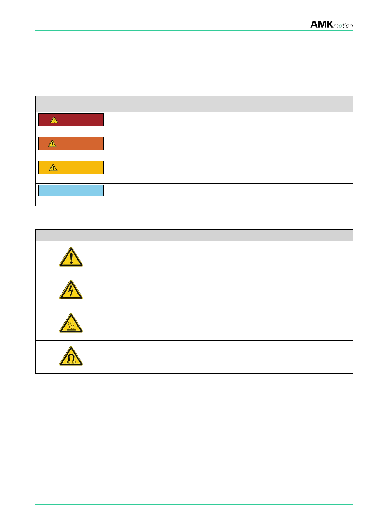
2.3 Presenting safety messages
Any safety information is configured as follows:
SIGNAL WORD
Type and source of risk
Consequence(s) of non-observance
Steps to prevent:
l...
8 / 74 PDK_204540_Motoren_SEZ / Version 2023/26